Designing a Low Cost XY Stage for Abrasive
Water Jet Cutting
by
Fadi Abu Ibrahim B.E. Mechanical Engineering American University of Beirut, 2002
SUBMITTED TO THE DEPARTMENT OF MECHANICAL ENGINEERING IN PARTIAL FULLFILMENT OF THE DEGREE OF
MASTER OF SCIENCE IN MECHANICAL ENGINEERING at the
MASSACHUSETTS INSTITUTE OF TECHNOLOGY June 2004
@ Massachusetts Institute of Technology All rights reserved
Signature of Author...
Certified by...
Accepted by...
-a-rt en ...- - ... bertment of Mechanical Engineering
May 10, 2004
-...-...
Alexander H. Slocum Professor of Mechanical Engineering Thesis Advisor
Ain A. Sonin Chairman, Department Committee of Graduate Students
ACKNOWLEDGEMENTS
Thanks first and foremost to God for giving me the talents and abilities to get this far, and for having me lucky enough to have my brother Feras. Feras I wish someday I will be like you. Thank you Rima, you are the best that happened to me since I moved to Boston. I also wish to thank my Dad, Mom, Hannoud, Rabih and Julie for their love and support.
Thanks to Alex Slocum for being the best advisor. He took me on board, gave me a great project and his guidance and expertise provided a great learning experience. I look forward to a prosperous future when me and Alex start making and selling our machines. This work was supported by iCampus, the MIT/Microsoft Alliance for research in educational technology, MIT's NSF Engineering Research Center, the Center for Bits & Atoms under Grant # CCR-0122419, a grant from Prof. Isaac Colbert, MIT's Dean for Graduate Students. I would also like to thank OMAX Corp. for their support and interest in building the parallel mechanism abrasive water jet cutter.
Thanks to Maureen Lynch for all her help. Thanks to Fred Cote for his always-present willingness to help in the machine shop and for teaching me so much about machining. Thanks to Ethan Crumlin for giving me the greatest help. Thanks to Jian Li, John Hart, James White and Shorya Awtar for their willingness to answer all my questions, and for being great friends. A special thanks to Jaime Werkmeister for remembering our birthdays.
Thanks to Marc and Carolina Graham for being the best friends I made in Boston, they where more than friends Marc and Carolina where family. Thanks to Bassel Younan and Karim Yehia for being the best apartment mates and for the
great friendship we established. Thanks to Tilman Buchner, Tarek Abu Fakher and Haitham Aawar for being my best friends.
ABSTRACT
Designing a Low Cost XY Stage for Abrasive Water Jet Cutting by
Fadi Abu Ibrahim
Submitted to the Department of Mechanical Engineering On May 10, 2004 in Partial Fulfillment of the Requirements for the Degree of Master of Science
In Mechanical Engineering
At the Massachusetts Institute of Technology
This thesis guides the reader through the design of an inexpensive XY stage for abrasive water jet cutting machine starting with a set of functional requirements and ending with a product. Abrasive water jet cutting allows for mass customization of 2D parts, such as inlaid tiles. Most water jet cutters are based on a prismatic-prismatic design (gantry type). In an effort to reduce the number of precision parts in the machine, a rotary-rotary parallel drive design is proposed. The proposed mechanism will be actuated by electric DC windshield wiper motors directly coupled to the links, this eliminates the need for gearing mechanisms that add up to the total cost and complexity of the design. Kinematics of the design is simulated for a working area of 310mm x 310mm. Dynamic analysis is performed and the concepts of decoupled and configuration invariant inertia are derived, simplified to a set of conditions on the kinematic structure/mass properties of the arm linkages and applied to significantly simplify the mechanism's control system. The XY stage was designed to be inexpensive and small enough to be placed in hardware stores, garages and small machine shops. A vision of water jet cutters sold in boxes stacked on shelves in Wal-Mart', available for all machinists, artists, schools, and industries might one day thus become a reality if the pumps could also be made cheaply.
Thesis Supervisor: Prof. Alexander H. Slocum Title: Professor of Mechanical Engineering
ACKNOW LEDG EM ENTS ... 3
ABSTRACT ... 5
INTRO DUCTIO N ... 13
1.1 Background... 13
1.2 W ater Jet M achining Overview ... 14
1.3 Concept G eneration... 15 1.3.1 First Concept...16 1.3.2 Second Concept... 17 1.3.3 Third Concept. ... ... 17 1.3.4 Fourth Concept... 18 1.3.5 Fifth Concept... 19
1.4 First Pass Com parison ... 20
1.5 Second Pass Com parison... 20
1.5.1 Sensitivity Analysis ... ... ... 21
1.5.2 Foot
Print...
...
22
1.6 Final Pass Com parison... 23
1.6.1 Fro Pr gn ... 23
CO NTRO L ACTUATION ... 26
11.1 Sketch .Bud.. ... ... ... 26
11.2 Actuation Mn... cU aTism s ... 27
11.3 Drive System s Actuators... 28
11.4 Link Design and Control Issues... 30
11.4.1 Dam ping . Ar... ... ... 30
11.4.2 Stiffnue s ... ... ... 31
11.4.3 Equations of M otion... 31
11.4.4 Over Heating... 32
11.5 Dynam ics and M odeling... 32
11.5.1 G eneral Dynam ics ... 32
11.5.2 M odeling ... 33
11.5.3 Arm Design: Two DO F ... 37
11.5.4 Application to the serial drive m echanism ... 39
11.5.5 Application to the parallel drive m echanism ... 39
11.6 Control Scenario ... 41
III FINA L D ... 42
111.2 Rotary Joint Concepts... 45
111.2.1 Cantilever Design ... 45
111.2.2 Yoke Design ... 47
111.2.3 C joint Design ... 48
111.2.4 Final joint Design ... 50
111.3 Motor Joint ... 50
111.3.1 Motor shaft connection ... 50
111.4 Couplings ... 53
111.4.1 Helical Bea m Couplings ... 53
111.4.2 High Torque Cou plings... 54
111.5 XY Stage Prototypes... 54 111.6 W ater Tank ... 55 111.7 Encoders... 57 111.7.1 Rotary Encoders ... 57 111.7.2 Modular E ncoders ... 58 111.8 Am plifiers ... 59 111.9 Joint Sealing ... 59 111.10 Bill of Materials ... 60 IV CONCLUSION ... 63
Benefits for Education ... 64
Future work ... 65
REFERENCES ... 67
APPEND IX A ... 68
Serial Drive Mechanism ... 68
Parallel Drive Mechanism : ... 70
RG mechanism ... 73
APPEND IX B ... 75
Retaining Rings... 75
W ave Spring ... 78
APPENDIX C ... 80
Block I: Motor joint drawings ... 81
Block II: Parallel arms drawings ... 82
Block Il: Preload drawings... 83
Block IV: W ater tank drawings ... 84
Figure I-1: Concept one... 16
Figure 1-2: Concept two... 17
Figure 1-3: Concept three ... 18
Figure 1-4: Concept four ... 18
Figure 1-5: Concept five ... 19
Figure 1-6: Sensitivity to error vs. Work area size (LxL)... 21
Figure 1-7: Foot Print vs. working area (LxL)... 22
Figure 11-1: Preliminary sketches of two possible rotary-rotary mechanisms... 26
Figure 11-2: Mounting the windshield wiper motor... 30
Figure 11-3: Lumping of links. (Total mass and center of gravity)... 33
Figure 11-4: Immobilizing joints... 35
Figure 11-5: (a) L=0 (b) r, =0... 38
Figure 11-6: Conditions 3 and 4... 38
Figure 11-7 Foot P rint ... . 40
Figure 11-8: PID controller designed to test the machine... 41
Figure 111-1: Squeeze joint prototype ... 43
Figure 111-2 A rigid joint prototype using half inch keyless bushing ... 43
Figure 111-3: Experiment setup with capacitance probes... 44
Figure 111-4 rigid joint bench level experiments... 44
Figure 111-5: CAD model of the Cantilever design ... 45
Figure 111-6: Cantilever design with (a) gravity preload (b) spring preload ... 46
Figure 111-7: Yoke joint design... 47
Figure 111-8: CAD model of the Yoke joint... 47
Figure 111-9: Yoke design experiment results... 48
Figure 1ll-10: C joint design ... 49
Figure Ill-11: CAD model of the C joint... 49
Figure 111-12: Deflection Tests C joint vs. Yoke joint... 49
Figure ll-13: Final joint design ... 50
Figure 111-14: Motor shaft / Driven arm connection ... 51
Figure 111-16: Motor joint machined with the shafts being aligned... 52
Figure 111-17: Shafts that fit tight to the wind shield wiper motor's output shaft... 52
Figure Ill-18: Helical beam couplings ... 53
Figure 111-19: Renbrandt high torque coupling ... 54
Figure 111-20: (a) CAD model, (b) Photo of Prototype I ... 55
Figure 111-21: (a) CAD model, (b) Photo of Prototype I ... 55
Figure 111-22: Water tank... 56
Figure 111-23: Encoder mounting model ... 57
Figure 111-24: E6D optical encoder. ... 58
Figure 111-25: 25A8 Amplifier by AMC... 59
Figure 111-26: Assembly for sealing the joints... 60
Figure IV-1: Finished machine ... 63
Figure IV-2: Mechanical parts fit a (40x30x13 cm3) box ... 64
Figure IV-3: Sketch of the 2 link serial drive manipulator. ... 68
Figure IV-4: Architecture of the proposed mechanism: ... 70
Figure IV-5: Four manipulator modes for the same tip location... 71
Figure IV-6: Sketch of the RG mechanism... 73
Figure IV-7: Shot from the Ajet simulation... 74
Figure IV-8: Sketches for modeling retaining rings... 77
Figure IV-9: Machine drawings... 80
Figure IV-10: Motor joint drawings... 81
Figure IV-1 1: Parallel arms drawings ... 82
Figure IV-12: Preload drawings... 83
Figure IV-13: Water tank drawings... 84
Table 1: Functional Requirements for the machine... 14
Table 2: First pass comparison of concepts ... 20
Table 3: Structural error sources... ... 24
Table 4: Resulting values from the error budget analysis... 25
Table 5: Machine Dimensions ... 27
Table 6: Bill of Materials and total cost of the machine ... 62
Table 7: Retaining rings. [5] ... .. 75
I
INTRODUCTION
1.1
Background
In a time when "better, faster, cheaper" are words to live by in the manufacturing world, the goal is to design a low cost XY stage actuated by two motors to be used in abrasive water jet cutting. Different techniques will be used to confirm a good quality at a low price. The design will be mainly targeted toward third world and evolving markets where precise machines at a low cost may be a solution to the current economic and industrial need to raise production quality. The machine should be inexpensive and small enough to be placed in hardware stores, garages and small machine shops for custom cutting any material. Not only companies will benefit from the design but also all technicians, artists, universities, school shops and people who will get the machine to turn their ideas into parts.
The purpose of designing a new machine is to best satisfy the needs of the customer who expects to profit from the investment. To achieve this goal, the Functional Requirements (FR) or static design goals, must be defined and used as the highest level of guidance. Hence the XY stage defined had to follow some
Functional Requirements Machineable area 310mmx3lOmm
Max acceleration 0.1g
Max velocity 10mm/sec
Resolution 0.5mm
Foot print Small
Cost 5$1500
Table 1: Functional Requirements for the machine
1.2 Water Jet Machining Overview
Abrasive jets have been in use in industry since 1982. Water jets, the precursor to abrasive jets, have been in use since 1970. Abrasive jets are widely used in the automobile, aerospace, and glass industries, to create precision parts from hard-to-cut materials. [1]
An abrasive jet uses water that is pressurized and then forced through a small sapphire orifice at about 2.5 times the speed of sound. Garnet2 abrasive is then
pulled into this high-speed stream of water and mixed together in a long tube. A stream of abrasive laden water exits the tube, and is directed at the material to
be machined. The jet drags the abrasive through the material in a curved path and the resulting centrifugal forces on the particles press them against the work piece. The cutting action is a grinding process where the forces and motions are provided by water, rather than a solid grinding wheel. [1]
Apart from the advantages of speed, accuracy and ease of use, abrasive water jet machining is also environmentally friendly (no oils, noxious gases or liquids) provides a quality sandblasted-like finish and involves no heat in the machining process (can therefore be used to cut materials with low melting points). [1]
One of the major factors limiting the extensive use of abrasive water jet machining is controlling the process. The linear speed of the abrasive jet nozzle must be varied for changes in the shape of the part. Abrupt changes in speed or excessive speed can result in poor quality. As a result of this abrasive jets are usually reserved for low-tolerance large runs, where hundreds of parts are created with a well-tested program, or for materials that cannot be machined in any other way. Today, OMAX3 is one of the leading abrasive jet machine providers and has developed software that can completely control the operation of the abrasive jet in an easy-to-use environment. [1]
1.3 Concept Generation
Five different general design concepts where developed and compared using simple calculations, along with an analysis for the simplicity of each concept. All concepts have the same water tank at the base; however the means of nozzle motion is unique to each concept.
In order to help do a first pass comparison of the concepts, a simple calculation was performed to measure the moment load on the support bearings. As the moment load on the support system increases, bigger bearings and more materials are required. The nozzle in each concept is assumed to be at its worst case position.
For simplicity in the concept generation stage, all structural elements of the concepts are assumed to be aluminum beams with a O.lmxO.lm cross section. The weight of the nozzle and the supporting components are assumed to be a 50N load at the end of the output beam.
1.3.1 First Concept
The first concept uses an X-Y axis system suspended upon the work space. The Y axis travels on the X axis that is aligned with the back of the machine. The nozzle travels back and forth on the Y-axis. Figure I-1 is a model of the first concept.
Figure I-1: Concept one
The moment load is calculated byM= >(FxD). Where Mis the moment
load on the base, F is the load and D is the distance between the load and the
base. Assuming the arms are 0.6m in length and weigh 50N, the moment load on
This concept requires two sets of linear motion systems and lengthy bellows to seal the linear bearings. Linear motion systems and bellows are expensive to buy, install, and maintain.
1.3.2 Second Concept
In the second concept shown in Figure 1-2, there are no cantilever arms hence eliminating bending loads down to zero. However one extra linear stage is
required and sealing is not simple due to the location of the linear stages very close to the water tank. The design is limited to cutting parts that are smaller than the bed size. The gantry also required two Y actuators to prevent racking. This concept is deemed infeasible when compared to the first concept, due to the extra costs and the complexity it brings forth to the machine design.
Figure I-2: Concept two
1.3.3 Third Concept
The third concept shown in Figure 1-3, utilizes a rotating arm suspended from the center of a frame that is positioned at the center of the water tank. The nozzle
traverses the rotating arm thus creating an RO motion system. This concept
opposite sides, thus reducing the load on the bearing system. However there are problems associated with it. The nozzle has to travel under the frame, which complicates sealing the axes. Secondly, having the water and abrasive lines follow the nozzle under the frame would be a difficult task. Lastly, the design is limited to cutting parts that are smaller than the bed size. This concept is deemed unfeasible compared to the first concept.
Figure 1-3: Concept three
1.3.4 Fourth Concept
The fourth concept, shown in Figure 1-4, is a 00 system. The nozzle, at the tip of the second arm, is positioned everywhere in the working area by two rotating arms. The lengths of the arms have to be slightly longer for the nozzle to reach the corners of the working area. However, the system uses two rotary joints, hence eliminating the need for sealing bellows and linear joints that are heavy and expensive. A weight of 20 N will be given to the arms in this concept, since no linear stages are mounted to the arms. The moment load at the base of the system was calculated to be 48Nm.
1.3.5 Fifth Concept
The Fifth concept, shown in Figure 1-5, is a modification of the RO system where an extra arm adds stiffness to the system. The rotary joint is located outside the working area hence solving all issues related to sealing, abrasive/water lines and part sizes. The moment load on the bearing base of the concept is 80Nm. The kinematics for this concept are formulated and simulated in Appendix A.
1.4 First Pass Comparison
Now that all the concepts are introduced, expensive and unfeasible ideas are discarded after a first pass analysis. Table 2 summarizes the concepts and their characteristics.
Concept Mb (Nm) Complexity and No of bearing Bellows Feasible
cost (1- 4) systems (Y/N) (YIN)
1 45 3 2 Y Y
2 -- 4 3 Y N
3 -- 4 2 Y N
4 48 1 2 N Y
5 80 2 2 Y Y
Table 2: First pass comparison of concepts
From the table, three feasible concepts emerge; concepts one (XYjet), four (Ojet) and five (Ajet). The three concepts are put through further analysis in a second pass comparison and a final concept selection stage to ultimately choose the best system for the machine.
1.5 Second Pass Comparison
In the second pass analysis the above concepts are taken into more detail and then compared based on the footprint and the sensitivity to errors from the actuators (backlash).
1.5.1 Sensitivity Analysis
The errors caused by angular deflections are the most troublesome, since these result in what is known as Abbe error.
Abbe - error = (offset _ dist) x sin (angle)
"Perhaps the greatest sin in precision machine design is to allow an angular error to manifest itself in a linear form via amplification by a moment arm". [2] Due to the importance of Abbe errors, a sensitivity analysis using MATLAB was performed by passing the machine throughout the working area and calculating the respective error amplification at the tool tip. The MATLAB script was
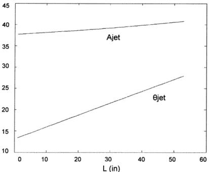
simulated for various working areas, noting the maximum Abbe error value corresponding to each working area. Figure 1-6 is a plot of the maximum Abbe error values versus working areas (LxL) for both the Ajet and the Ojet. The Abbe errors due to the actuators are zero in the XYjet. The sensitivity to errors in the Ajet is higher than that in the Ojet and in both concepts the sensitivity values increase as the working area gets larger.
45 40- -Ajet 35-30 Abbe Error 25-2jet 20 15 10 .. ... .... ... .... ... ... - ... ... .. ... 0 10 20 30 40 50 60 L (in)
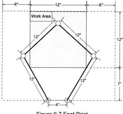
1.5.2 Foot Print
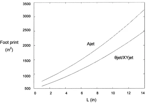
Foot print, or the total area taken by the machine in the workshop, is a major functional requirement. The smaller the footprint, the more appealing the design. The working area was changed form 12.5x12.5 to 25x25 in 2 for each concept,
and the respective footprint was calculated via a MATLAB code. Figure 1-7 is a plot of the Foot Print vs. working area for both the Ajet and the Ojet. It is noticed that the footprint of the Ajet is bigger then that of the Ojet and the XYjet. The
ejet
is not as stiff in the Z direction as the Ajet however that could be accounted for, as shown later in Chapter I1. Theejet
and XYjet are taken into the final pass comparison stage,3500
3000
2500
Foot print 2000 Ajet
(in2 ) 1500 - ~Bjet/XYjet 1000 500 0 2 4 6 8 10 12 14 L (in)
1.6 Final Pass Comparison
1.6.1 Error Budget
In order to represent the relative position of a body in space with respect to a reference system, a 4x4 matrix is needed. The matrix is called the homogeneous transfer matrix. The first three columns are direction cosines (unit vectors i,
j,
k) representing the orientation of the body with respect to the reference coordinate frame. The last column is the position of the body with respect to the reference frame. This summary is explained in full detail in [2]Oa Ol Ol P,
n R= JX 0 Jy 0JZ
PY
Ox 0 k Okz Pz
_0 0 0 1
The upper superscript is the reference frame in which the results are desired to be represented in. The subscript is the reference frame from which you are transferring. It follows then that the equivalent coordinates of a point in a coordinate frame n with respect to the reference frame R, are
~XR Xn
Y,=R
ZR _Zn
In this case, there are three reference coordinate systems, the position of the tool tip with respect to the reference one will be: TR = TR2T2 . All rigid bodies have
bearings, deflections due to loads, thermal distortions, etc. The goal in error budgeting is to allocate allowable values for each. For any machine member, the error matrix describing its error in position with respect to its ideal position is:
1 6,
-o,
1 -6, , 1Y 0 0S
(y 6, 1 1 6, 0 -6, 6y , Y1
16 0 0 a + C+ I Where a, b and y and z. Sincec are the distances between the cutting tool is a jet of
the two coordinate systems in the x, water the lateral direction is not a sensitive direction, hence the total error in that direction is not as important as the one in the x and y. Error sources are sketched and formulated in Table 3.
FE FL2 ... 3EI 2EI ML ML EI EI F 5 FE 192EI M 3 ML 12EI a <F Fa2(a-3L) Fa2 .. . ... 6E I 2EI TL Torsion 6= GJ FL Tension / Compression 6 = AE
Table 3: Structural error sources TR
After specifying the sources of systematic errors, each member was individually taken. The deflections and machining and random errors where taken and entered into the E matrix to give the homogeneous transfer function matrix. Table 4 shows the resultant errors in the x, y and z directions. A MATLAB code was developed based on the above formulations. The numerical results were proved correct by running the analysis using an EXCEL spread sheet designed by
Slocum et al.4
Concepts 5X 5y 5z
Ojet 0.0016 -0.0019 -0.1616
XYjet 0.0011 0.0014 -0.0695
Table 4: Resulting values from the error budget analysis
For an estimate cost of $1500 and a not so high resolution of 0.5mm, the
ejet
is the best mechanism for the low cost XY stage. The Ojet's low stiffness in the Z direction will be taken into account in the next section.II
CONTROL
/
ACTUATION
11.1 Sketch
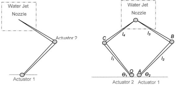
A sketch of the series drive rotary-rotary mechanism is shown in Figure I-1a. An alternative mechanism that is stiffer in the Z direction can be a 5 link parallel drive mechanism where the motors are both at the base. Figure l-1b is a sketch of the parallel drive mechanism. Table 5 gives some first dimensions for the machine to carry on with the analysis. Most of the concepts and the calculations in this chapter are based on [3] [4].
Water Jet Water Jet
Nozzle Nozzle
I, 12
A
Actuator 1 Actuator 2 Actuator
1
Machine Dimensions
Arms Length (L1,L2) 35cm (14")
Arm Cross Section 380mmx25mm (1.5"x1")
Material Aluminum 6061
Table 5: Machine Dimensions
11.2 Actuation Mechanisms
Research in the field of parallel drives analyzes and optimizes the kinematics however it does not always stress means of actuation, structure simplicity and controls. A robot can be actuated through a direct drive mechanism or through transmission. With a transmission, the reducer must supply the necessary gear reduction while maintaining the proper precision level by introducing no backlash to the link. When the word backlash is read, the first idea that pops into the mind is "preloaded gears", but what about the friction in preloaded gear mechanisms and the complexity of building a preloaded gear structure. Friction is unpredictable and large values lead to poor control accuracy, by producing friction torques in the force control system. In addition, gearing mechanisms are a source of compliances, and low mechanical stiffness causes arm deflections and limits the dynamic response. If the higher order delay from the low stiffness makes the system unstable, then the loop gain of the system cannot be increased. Poor stiffness at the gearing also causes vibration, a critical issue for high speed manipulation, where the robot reaches a certain position and cannot move to the next step.
In a direct drive mechanism the motor's rotor is directly coupled to the link, thus potentially eliminating gearing completely. This results in friction and backlash
being removed except at the bearings, and a reliable stiffer mechanical structure with no gears to wear. The joint consists of a motor, a set of arm links and the bearings. This will result in a better control performance, and improved position accuracy. Since the construction uncertainties in this simple structure are greatly reduced, a higher precision, simple dynamics and better system response are expected. However, a direct drive motor requires very high torque and current drives which can result in very large motor size, inertia, and cost. The direct drive mechanism will be taken into more detail in the sections to come. But next the drive systems and actuators will be discussed.
11.3 Drive Systems
/
Actuators
For mechanisms with linear actuators, several options of actuation are available: hydraulic, pneumatic, piezoelectric, electric, etc... However for revolute joints, electric motors are the best choice to use. Key components in the design of the robot are the motors and the drive amplifiers. There should be enough torque at all times; In addition, torque fluctuations should be minimized in order to achieve accurate control. Direct Current (DC) motors or Brushless D.C. torque motors can be used
A direct drive DC motor consists of a stator, rotor and bush rings. The torque is exerted at the air gap between the rotor and the stator, and it is proportional to the diameter of the rotor. That explains why motors with a large diameter and short rotor lengths are used in direct drive robots. In an ideal motor the Torque is constant, however in reality it varies as the rotor rotates which results in Torque ripple that prevents smooth motions and accurate control.
DC motors have high efficiency, low torque ripple, linear torque speed characteristics and simplicity of construction. However in these motors the large
currents delivered to the rotor are through mechanical commutators, as a result sparks can be generated causing the brush to wear, and producing unwanted noise.
Brushless DC motors replace the mechanical commutation with electric switching circuits. No sparks are generated while preserving all the previous characteristics of DC motors. The setup of such motors is different; the rotor has the permanent magnets and the stator carries the coils. The coils being placed on the stator that has a bigger surface area than the rotor results in better heat transfer and cooling of the coils. The position of the rotor is located through a position sensor and accordingly the proper switches are triggered. Two problems are faced with these motors: First, they are expensive. Second, there is a Torque ripple when the switches turn on and off as the motor rotates. Hence, for designing the 2D planar robot a conventional DC motor will be used.
In an attempt to reduce the price of the machine and make it easy to build anywhere in the world it is hypothesized that DC windshield wiper motors will be used. These motors are widely available; people interested in building the machine themselves can get them out of old cars. The motors typically are not back-drivable due to an internal worm gearbox, have a tolerable backlash, a stalling Torque of 14 Nm and a no load speed of 81 rpm. These motors are very easy to mount as shown in Figure 11-2 and posses enough Torque to actuate the machine at the desired speeds. Backlash in the motors can be reduced by the spring preload from the high pressure water supply tube and future control schemes to be designed.
M6 bolt :
M6 head screws
Aluminum flange
Figure 11-2: Mounting the windshield wiper motor
11.4 Link Design and Control Issues
If one motor is at the end of the first link, the robot becomes heavy because the first link and motor must support and drive the second link and motor. The weight of the motor that drives one link is a load on the motor that drives the previous link. As a result the required torque needed to drive individual links increases exponentially, therefore the sizes of consecutive motors increases exponentially. Another design that can be used to solve this problem is to have the motors at the base, and then transmit the torque to the links through respective links. Then the challenge becomes to overcome the complexity added to the design through the extra mechanical links.
11.4.1 Damping
In direct drive systems the bearings are the only source of damping, hence we will be dealing with an almost zero damping situation that is very hard to control. This is because when the inertial load to the mechanical damping coefficient is
large the back emf of the motor yields a damping effect. This electromechanical damping effect is less than the amount needed to stabilize the system response. Velocity feedback compensation is a good way to deal with this problem, but one
must set the gain K, very high to get the required responses. In addition, a high performance sensor is needed to accurately measure the slow speed of the motor (same as velocity of the link) that isn't affected by noise disturbances.
11.4.2 Stiffness
The robot's endpoint static stiffness is the ability to maintain a commanded position in the face of external loads. This stiffness is determined through the mechanical construction of the system as well as the feedback loop gains of the individual servo systems. In a gear-drive system the output torque is amplified by the gear ratio which is not the case in a direct drive system. Therefore the direct
drive robot needs a higher controller gain.
11.4.3 Equations of Motion
Nonlinear and highly coupled is the general behavior of a manipulator arm. Equation 2-1 gives the dynamic equation of the i' motor:
Jo,+ """1a + "P+ "non (2-1)
no 2i nmon
Where r,,on -rvO r,,, are the nonlinear, coupling and motor torques. n, is the gear ratio of the ith motor in the mechanism. J. is the arm inertia that varies
depending upon the arm configuration. Jotor is the rotor inertia, invariant. a, is the motor's angular acceleration. Note that the nonlinear and coupling torques are attenuated by the gear ratio, where as depending on the gear ratio the variations of Jarm will be attenuated byn2.
11.4.4 Over Heating
From Equation 2-1, it can be noticed that the gravity load is attenuated byn, (z>,0,/n,), thus in a direct drive mechanism when the motor is at rest gravity is attenuated. Gear friction produces a torque that would oppose the gravity torque; in direct drive systems this is no more present. Hence the motors will take the gravity load entirely and continuously, which will over heat the actuation system. When choosing the actuator special attention should be placed on the overheating problem. However in our planar robot there are no gravity loads.
11.5 Dynamics and Modeling
11.5.1 General Dynamics
The equation of motion for the manipulator arm:
'ri =Hii~i+JHY~j+ZZf ally lHk j Ok + irgj
(2-2)
rj = H( , a,( 2
a0i
Where T, ,rg, are the joint, gravity torques. 0, is the joint displacement. H, is the i-j element of the inertia matrix. The first term in the inertia matrix is determined by the kinematics structure of the manipulator arm and the mass properties of the links. Therefore a design problem is to reduce the inertia to a diagonal form that gets rid of the second term in Equation 2-2. (the inertia torque caused by the other accelerating links).
r=H O±, k H 1 8HaH 'k i
I Ill 80, 2 0 9 , J
(2-3)
Nonlinear velocity torques, given in the second term, result from the spatial dependency of the diagonal elements on the inertia matrix. But if we can figure out a way to make the inertia matrix independent of the link configuration then the third term in Equation 2-3 is eliminated to give:
(2-4)
Now the system is linear and decoupled, and can be treated as a SISO (single input, single output) system.
11.5.2 Modeling
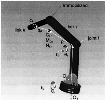
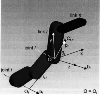
Consider a robot with a serial number of links. Let 1 be an arbitrary joint number.
We then imagine all the joints between 1+1 and n immobilized and combined as
one rigid body.
Figure 11-3: Lumping of links. (Total mass and center of gravity)
Kinetic energy stored in the links can be modeled as:
T=Z(M
v 7 v~ + OjTiw )/12X=I
(2-5)
k
Where
mkis the mass of link k,
'kis the inertia tensor of link kI
VCk = Zb, 9j X r,cki=1
is the linear velocity of the centroid of link k and co, = of link k. Substituting Vck and into Equation 2-5 gives:
k
Lbi 9,
i=1
is the angular speed
k k T = I( H,, i=1 j=1 . 2 n H,, = Itmkb .rl , r~,Ck k=max[Qi] -bik .bIr, )+b
lkb
Let Mn Cin and pi be the mass, centroid of the (n-i+1) links and the position between 0 and Cio
n MI,n = IMk k=1 = k=1 MKI~n (2-8) (2-9) (2-10) (2-11) rick =r +pj+qk n Im qj = 0 k=1
Substituting the above equations into Equation 2-7 gives which can be
divided into two parts: one involves terms associated with the last (n-1+1) links (2-6)
and the other for the other links. Let N,, be the inertia tensor of the n-1+1 links
relative to C, .
Hy = [ [mk(bib, .rT rTk -br JbkTrck)
+bfIkbj
]
+ bTN,,b
k=max[i,j] (2-12) +M [b,Tbj (r1 + P, )T (r 1 +p1) ,(r> + p1 ).bT (r,+p,)We will first try to set the off diagonal elements to be invariant or zero for all arm configurations. Note the sketch in Figure 11-4, the inertial frame O-XYZ is located to coincide with 0, and the Z axis is set in the direction ofb,.
Figure 11-4: Immobilizing joints
L1,n cos9, p,= L,, sin 01 .0 cos01 -A= sinO, C 0
I
;in 0, 0 0 0 Rotation matrix I-(2-13) (2-14)N = ANA T=NXY N (2-15)
NX NZ NZ
If b, is not perpendicular tob, the x-y plane intersects b, atO,. The position vector of0, , r, and the direction cosines of the ith joint axis are given by:
rX r,, = 0o, = ry (2-16) r bX b= b, (2-17) b
Substituting the above:
H =(ML2 + Nbz+(bxNxz +b, Nyz + MLbzr,)cos0 (2-18)
+(b, N, - b, Ny, + MLbr,) sin 0
For Hil = 0, all three terms in Equation 2-1 must be zero. N.Z > O,ML2 > 0 -> For the first term to be zerob. =0. This implies that the two joint axes have to be perpendicular to each other which in turn limit the design options to 2D. Second and third terms = 0=> N,, =O,N = MLr,. As for the diagonal parameters, from Equation 2-12 we get:
H1 =(m [k2 - (bi,, )2
])
+ bTANATb, + (2-19)k=i
M , +P, --[bT (r,+ p, )
Calculations similar to those for the non diagonal elements can be performed. Summarized below are the necessary conditions that the kinematics and the
mass properties the arm must satisfy for the diagonal/off-diagonal H elements to be "invariant". Condition 1: Condition 2: Condition Condition
b, = b, The two joint axes are parallel,
b Tb 0 and r =r, =0 -o(Oi=O), and N M =,and N+ MUL2=N 3: b b, = 0, and L=O and N
=Oand
N d 4: b b =0 and ry=0 Nx =N,, + M11.5.3 Arm Design: Two DOF
An open kinematic chain manipulator arm has a decoupled inertia arm if the joint axes of the two links are orthogonal:
Condition 1: m2Lr, = N,
Condition 2: NZ = 0
Two specific cases arise when L = 0 and rz = 0. Conditions 1 and 2 are shown in L2
Figure 11-5: (a) L=Q (b) r, =0
For invariant inertia, conditions 1 and 2 apply. But suppose we take the case where the joint axes are not normal to each other (b, 0), in that case the above two conditions apply in addition to the following conditions:
Condition 3: b =1,(b,= b =0)
L =0
Condition 4: r =ry y =0
N =N =N =0
N +ML =N,
Conditions 3 and 4 are sketched in Figure 11-6.
Mechanisms with oblique arms are seldom used and not practical (Figure 11-6). A 3DOF system is reduced to a 2DOF one by immobilizing one of the links. Such mechanisms are designed by building two 2DOF models above each other. From the previous section we derived four conditions and sketched the equivalent model for having an invariant inertia matrix. The fourth Condition will be ignored.
11.5.4 Application to the serial drive mechanism
For the serial drive mechanism the inertia matrix derived in Appendix A can be summarized by:
H
I=
ml, +11 +m2(12 +l 2 +2A4l2 cos 02)+12H22= m2lc2 + I2
H12 =m2112 cos+ M21c2 + I2 h=m2i1!n sin 02
Since H, and H2 depend on 02, they are configuration dependent and cannot
be reduced to zero for all 02 by changing the mass properties. The only way for this to work is to have the joint axis pass through the centroid of the second link, which is not logical from a design point of view.
11.5.5 Application to the parallel drive mechanism
Appendix A gives the formulation of the kinematics and dynamics of the parallel drive mechanism. Inertia matrix H:
H=[Hu
H:]
_H1 H21
H2 2 = 4 +m4 4 + 12 +m2,2 +m1l2 H12 = (m3121c3 ~ M41Ic4 ) COS(02 - 0
From the inertia matrix, we notice that H1 and H22 are independent of the
configuration however H1 2 depends on the angles , and92. To have a simple
decoupled inertia matrix we can reassign values for the mass and the dimensions of the manipulator links, so that the inertia term H2 goes to zero.
m3u21c3 - m4u11c4 = 0 -> M _ 11c4
3 ~ 2 3210c ~ - mM
Satisfying the above condition results in a completely decoupled and invariant inertia matrix. Hence the parallel drive mechanism has an unprecedented advantage over the serial one and is the mechanism of choice on the water jet cutter. Figure 11-7 gives the foot print (19" x 24") and the mechanism dimensions for the detailed design of the machine. An experimental setup to test for decoupling between motors is to let one motor track a sinusoidal position command while keeping the other motor at rest. The peak-peak ratios between the actual position signal of the driven motor to that of the stationary one is a
measure of coupling in the arm dynamics.
122
12i F P12-
72"
11.6 Control
To test the machine a simple PID controller was developed as shown in Figure 11-8.
(
01802PID
i1, 2aci)
Figure 11-8: PID controller designed to test the machine
Scenario
III
FINAL DESIGN
The machine requires both rigid and rotary joints. Two concepts for the rigid joint and four for the rotary one are presented. The reader is guided through a design process to select the concepts that best serve the functional requirements while maintaining simplicity in assembly, ease in fabrication and the use of standard components that are cost effective.
111.1 Rigid Joint Concepts
To rigidly mount the shaft to the mounting arm, two joint concepts were analyzed. The first one is that of a squeeze joint while the second one utilizes a keyless bushing. The squeeze joint concept is a traditional approach for attaining rigid connections, where the shaft is squeezed in both lateral and axial directions, to the mounting arm. Figure Ill-1 displays a squeeze joint prototype fabricated for a
Figure 111-1: Squeeze joint prototype
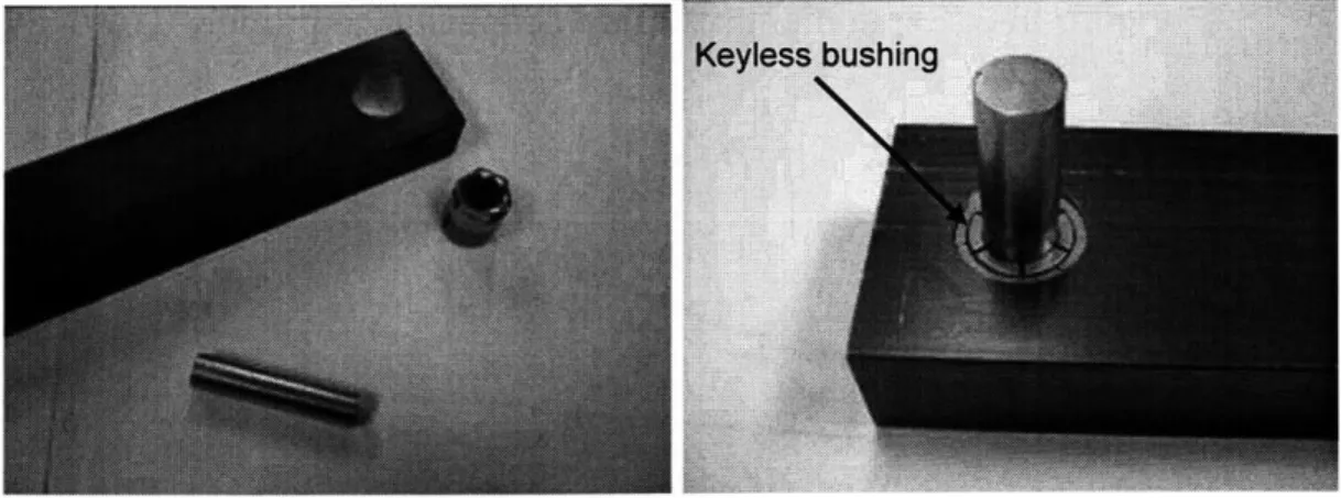
Keyless bushings are components with inner and outer sleeves connected via a collar nut. As the collar nut is tightened, the inner sleeve contracts grabbing the shaft while the outer sleeve expands grabbing the mounting arm. Mounting the keyless bushing requires a roughly finished hole to be drilled in the arm. Keyless bushings have been used to attach axles to wheels; our application is novel to the usage of this hardware. A rigid joint prototype using half inch keyless
bushings by Fenner Drives' was fabricated as shown in Figure 111-2.
Keyless bushing
Figure 111-2 A rigid joint prototype using half inch keyless bushing
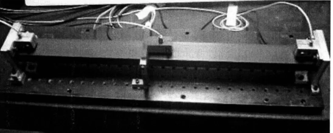
A bench level experiment was set up to compare the load-deflection curves of each concept. Figure 111-3 is the machined setup. Capacitance probes hooked up
to DSpace6
were used to measure stiffness. To test the accuracy of the test bench, a whole beam was tested on the setup and data obtained where compared with theory. The accuracy of the system came out on the sub micron level. Figure 111-4 is a chart with both the experimental and numerical results for the two prototypes. The results from the keyless bushing joint stiffness test were comparable to those from the squeeze joint test. Hence the keyless bushing concept was selected for the rigid joints due to the simplicity in fabrication and assembly it brings forth to the design.
Figure 111-3: Experiment setup with capacitance probes
2 3 4
load (kg)
- MATLABwhole beam -4-full-beam exp
+key-less bushing exp +M PROEkeyless bu.
-A- squeeze joint
Figure 111-4 rigid joint bench level experiments
6 http://www.dspace.com.au/index.shtml 250 200 150 100 50 0 0 1 5 6 7 8
111.2 Rotary Joint Concepts
Four rotary joint concepts where analyzed at the details level. The four concepts will be compared based on the overall stiffness, errors, simplicity and ability to accommodate the cheapest means of preloading the bearings. The concepts are given the names: Cantilever design, Yoke design, C design and Final design.
111.2.1 Cantilever Design
Starting with a simple concept for the joints, a CAD model of the Cantilever design is displayed in Figure 1-5. Using off-the-shelf bearings in the machine is one of the design goals. Therefore using 8mm deep groove ball bearings that are available world wide on roller blades became a functional requirement. However, numerical analyses on the cantilever arm design with the 8mm deep groove bearings resulted in large Z-axis deflections. Hence, 12 mm angular contact ball bearings were selected for this design. The angular contact bearings were oriented in a back-to-back position to obtain the greatest stiffness and to maintain thermal stability. The issue of preloading in a simple low-cost manner came into the picture next.
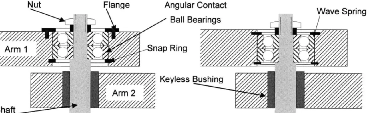
Two schemes of preloading where investigated: gravity preloading for the deep groove bearings and spring preloading for the angular contact ones. With gravity preloading the joint and bearings utilize the applied mass on the arm and the force of gravity to adequately remove backlash within the bearings. Gravity preloading is a very convenient method that enhances simplicity in the design and significantly reduces machining time. Figure 111-6 (a) is a sketch of the Cantilever joint design with the 12mm bearings preloaded by gravity. Gravity preloading was not adequate in providing the necessary preload for the cantilever design. Spring Preloading on the other hand requires spring forces applied on the bearings. This complicates the design and increases the total machining time. The spring preload scheme in the design used a wave spring to provide the spring force and snap rings or steps machined to the shaft or the arms to properly constrain the bearings. Figure 111-6(b) is a sketch of the cantilever design with spring preloading using a wave spring and a snap ring.
Wave springs manufactured by Smalley®7 are a compact design reducing spring
cavity by 50% with equal deflection. Calculations for modeling the wave rings and snap rings for 12mm angular contact bearings are presented in Appendix B. In the attempt to reduce the machining cost, the cantilever design for joints was discarded.
Nut Flange Angular Contact Wave Spring
Ball Bearings
1Snap Ring
Keyless Bus
~ Arm
Shaft
Figure 111-6: Cantilever design with (a) gravity preload (b) spring preload
111.2.2 Yoke Design
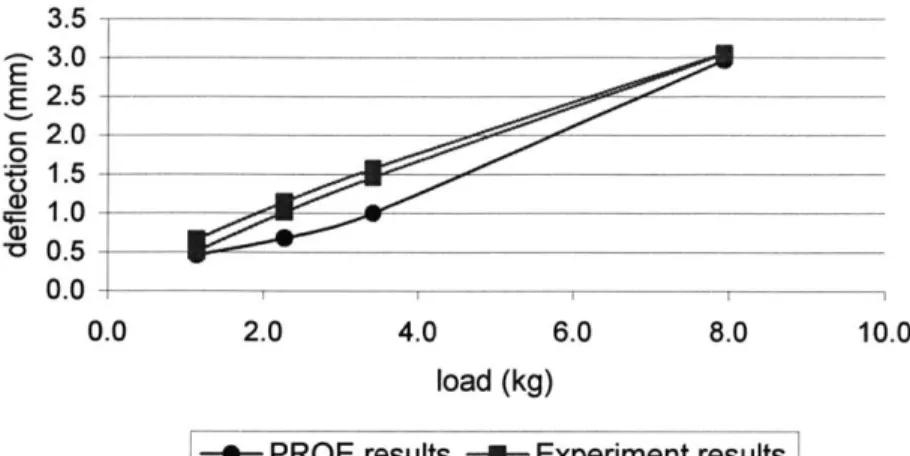
To have a joint stiffer than the cantilever design and that is capable of using the lowest cost 8mm deep groove ball bearings, a yoke model as shown in Figure 111-7 was developed. To perform numerical analysis on the Yoke design a CAD model, shown in Figure 111-8 was developed. The bearings and keyless bushings where modeled as shown in drawings 8 and 9 of Appendix C and assigned the properties of Aluminum 6061. Numerical analysis results were compared to test data of the actual prototype in Figure 111-9. Machining the yoke prototype is expensive, an issue that adds extra cost to the fabrication process.
Nut\ Flange Arm 1 haft Deep Groove Ball Bearings Arm 2 Keyless Bushing
Figure 111-7: Yoke joint design
3.5 3.0 E 2.5 c 2.0 0.~1 1.5 1.0 V 0.5 nn I 0.0 2.0 4.0 6.0 8.0 10.0 load (kg)
--- PROE results -4- Experiment results
Figure 111-9: Yoke design experiment results
111.2.3 C joint Design
To simplify the Yoke joint's machining process while keeping the same level of stiffness in the Z direction, a new C concept as shown in Figure 111-10 was designed. To perform numerical analysis on the C design a CAD model, shown
in Figure 111-11 was developed. The bearings and keyless bushings where
modeled as shown in drawings 8 and 9 of Appendix C and assigned the properties of Aluminum 6061. Numerical analysis results were compared to test data of the actual prototype in Figure 111-12. The C concept with no precision dimensions, and a good stiffness in the Z axis using the 8mm gravity preloaded bearings, made it the best concept so far. The Yoke concept though stiffer was deemed unfeasible due to the complexity associated with it. The C joint was selected to build a first full scale prototype of the machine.
Bolts Arm 1...N t Deep Groove Ball Bearings Arm 2 ushing
Figure 111-10: C
joint
designFigure 111-11: CAD model of the C joint
2.0 4.0 6.0 8.0 load (kg) Flang Keyless E Shaft E 0 6.0 5.0 4.0 3.0 2.0 1.0 0.0 0.0 10.0
-U- Experiment Yoke-Joint -4- Experiment C-Joint -1- PROE C-joint
Figure 111-12: Deflection Tests C joint vs. Yoke joint -- 1
111.2.4 Final joint Design
To take further advantage of gravity preloading in the C joint while reducing the stresses on the bolts, an inverted C joint was modeled as shown in Figure Ill-13. The Final joint was selected to build a second full scale prototype of the machine.
Flange Deep Groove
Ball Bearings
Keyless
Bushing X
Arm
Figure Ill-I13: Final
joint design
11.3 Motor Joint
11.3.1 Motor shaft connection
In the first prototype, the concept of a squeeze
joint
is used to couple the motor's
output shaft and the driven arm. A half inch shaft is adhesively bonded with
Loc-Tite to the motor, and then squeezed in both lateral and axial directions relative
to the mounting arm. The setup is shown in Figure Ill-1. The squeeze joint on the
motor output shaft did not provide enough stiffness in the Z axis. As a result a
modified version of the Final
joint
was used to couple the motor's output shaft to
the driven arm. Figure 111-14 is a CAD model of the motor's connection.
Deep Groove Ball Bearings
Keyless Q
Bushing-- ---- Arm 1
Driven arm shaft
High Torque
Coupling
-MMotor output shaft
Motor mounting holes Wind Shield Wiper
Motor
Figure 111-14: Motor shaft / Driven arm connection
To simplify the fabrication process, very few precise dimensions where required in the parts' specifications. Hence misalignment between various blocks of the machine was eminent. To account for such misalignments between the motor's output shaft and the driven arm's shaft, the motor's mounting holes where made slightly bigger so that motor can be moved around until perfect alignment between the two shafts is achieved via a rigid coupling designed and fabricated specifically for this task. Figure 111-15 is a photo of the machined rigid coupling.
Figure 111-16 is a photo of the machined motor joint.
Figure Ill-16: Motor joint machined with the shafts being aligned
A CNC code was developed to machine shafts that precisely fit to the motors almost square output shaft cross-section. A photo of a fabricated shafted is displayed in Figure 1ll-17.
Wind Shield wiper motors Shaft
111.4 Couplings
The output shaft from the motor-gear combination cannot handle significant direct radial loads. That was obvious when the squeeze joint concept in the Motor Joint failed. Radial shaft loads cause bending moments which decrease efficiency, stall the motor and lead to early failure of the transmission. To obtain sufficient stiffness at a high performance, a high torque coupling should be used to connect the motor output shaft to the driven arm's shaft. Helical beam
couplings, high torque couplings and flexure type couplings are discussed next.
111.4.1 Helical Beam Couplings
Helical beam couplings are often used to transmit rotation from one shaft to another. The shaft coupling's simple one piece construction discards all forms of friction wear within its design, while ensuring a zero-backlash and a no torque-loss operation. Cyclic vibration caused by off-center loading is reduced due to the shaft clamping squeeze type arrangement being incorporated into the single design. However, one of the main obstacles in high-torque applications is one of torsional deformation due to the coupling's modest torsion stiffness. The stiffest helical beam couplings in the size range available can handle operating torque of 4Nm. However, joint torques of 10 Nm are not unusual. Figure 111-18 is a photo of the helical beam couplings.
111.4.2 High Torque Couplings
Renbrandt8 couplings are especially designed for precision instruments, robotics
and encoder drives. Their features include: zero backlash, low inertia, torsional rigidity, uniform velocity, no friction and a long life. The couplings have an accurate concentricity that is unaffected by dust or corrosive atmosphere. The high torsional stiffness of those couplings is due to discs with hubs mounted at 90* with respect to each other. The optimum design for high torque necessitates a compromise in increased radial stiffness that diminishes the coupling ability to handle shaft misalignments. Figure 111-19 is a photo of the Renbrandt coupling purchased for the machine. Those couplings are inexpensive to purchase and overcome a peak torque of 88Nm as opposed to a 9Nm peak torque with the same size helical beam ones.
Figure 1I1-19: Renbrandt high torque coupling
111.5 XY Stage Prototypes
Two full scale prototypes were fabricated. Figure 111-20(a) is a CAD model of the full scale Prototype I and (b) is a photograph of the fabricated model. Figure
111-21(a) is a CAD model of the full scale Prototype 11 and (b) is a photograph of the fabricated model.
Figure 111-20: (a) CAD model, (b) Photo of Prototype I
Figure 111-21: (a) CAD model, (b) Photo of Prototype I
111.6 Water Tank
All abrasive water jet cutters require a tank full of water at their base to receive the jet of water and abrasive, reduce noise and eliminate the mess from the process by having the part under the water level. This water tank design is based
on a tank previously designed by Varela and Slocum. [8] The tanks are to be cast out of polymer concrete using a two part mold with a parting line at the tank's rim. To create space on the front side of the tank a draft angle of 100 was used as opposed to a 3* draft on the other sides of the tank. The tank will incorporate two
posts that allow the XY stage structure to be directly bolted on them. The rim of the tank is 30" high and the posts are 6" above the rim, which puts the central plane of the parallel arm mechanism at 18" above the rim. Figure 111-22 is a CAD model of the water tank.
Mounting Surfaces for Axes Assembly
Slits for Fins
Figure 111-22: Water tank
Based on the OMAX machine, hot-dipped galvanized steel fins will be used to support the work piece. The fins will need to be replaced periodically as the water jet cuts through them with time. The slots for the fins will be designed into the tank mold so that no additional hardware will be needed to hold the fins in place. [8].
111.7 Encoders
111.7.1 Rotary Encoders
Rotary encoders convert shaft rotation into square wave output pulses which are then digitized to indicate position, velocity, and direction. They mount to rotating shafts of motors, conveyors, and measuring wheels. An encoder's resolution is measured in cycles per revolution. Due to the mechanical components in such encoders, the prices associated with them tend to be high in the range of $100 to $300 for a resolution of 1000 to 2000 lines per revolution. Two rotary encoders are used in the first prototype and are connected to the output shaft via a helical beam coupling. Flexible couplings are an essential hardware to use in such cases due to the encoder's incapability to handle radial loads and machining misalignments. Figure 111-23 is a model of the motor output shaft connected to the encoder. Rotary encoders have their own shaft and support bearings, Modular encoders on the other hand use the machine's existing shafts and bearings as discussed in the next section.
Encoder
Helical beam coupling
Wind shield wiper
Mounting Arm motor
111.7.2 Modular Encoders
Modular encoders offer a high resolution up to 2048 cycles per revolution for an affordable price of $50 to $80. A quote from US-Digital@ 9 on a simple and low cost optical kit encoder (E6D) made it ideal for this application. E6D is a non-contacting rotary to digital position feedback device designed to easily mount to and dismount from an existing shaft. The internal monolithic electronic module converts the real-time shaft angle, speed, and direction into TTL-compatible outputs. The kit consists of five parts: base, cover, hub/code wheel, module, and the internal differential line driver. The base and cover are made of rugged 20% glass filled polycarbonate. The hub/code wheel adapts to the 8 mm diameter of
our shafts. Figure 111-24 is a photo of the E6D modular encoder.
Figure 111-24: E6D optical encoder. 10
9 http://www.usdigital.com
111.8 Amplifiers
Searching for amplifiers that are small in size, easy to use, low in cost and based
on the surface-mount technology led to Advanced Motion Controls (AMC)* ".
The 25A Series PWM servo amplifiers are designed to drive brush type DC motors at a high switching frequency. An LED indicates the operating status. Over-voltage, over-current, over-heating and short-circuits across motor, ground and power leads are protected for in the models. The models interface with digital controllers such as DSpace in our case. Loop gain, current limit and input gain are adjusted using potentiometers. Figure 111-25 is a photo of the 25A8 amplifier selected for our application.
Figure 111-25: 25A8 Amplifier by AMC
111.9 Joint Sealing
Due to the dirty working environment in abrasive water jet cutting, all the joints had to be sealed from splashing water and abrasive. This was accomplished