Development of a Powered Transtibial Prosthesis
for Ball Room Dancing
by MASSA
Nathan Villagaray-Carski
J
Submitted to the Department of Electrical Engineering L and Computer Science
in Partial Fulfillment of the Requirements for the Degree of Master of Engineering in Electrical Engineering and Computer Science
at the
MASSACHUSETTS INSTITUTE OF TECHNOLOGY
June 2014
Copyright 2014 Nathan Villagaray-Carski. All rights reserved. The author hereby grants to M.I.T. permission to reproduce and to distribute publicly paper and electronic copies of this thesis document
in whole and in part in any medium now known or hereafter created.
Author
...
Signature redacted....
Department of Electrical Engineering and Computer Science
Signature redacted
May
22, 2014Certified by... ...
Hugh Herr Principal Research Scientist
Signature redacted
Thesis
Supervisor
Accepted by . ... ...
Prof. Albert R. Meyer
CHUSETTS MN1ftE F TECHNOLOGY
JL 15 2014
IBRARIES
Development of a Powered Transtibial Prosthesis for Ball
Room Dancing
by
Nathan Villagaray-Carski
Submitted to the Department of Electrical Engineering and Computer Science
May 22, 2014
In Partial Fulfillment of the Requirements for the Degree of Master of Engineering in Electrical Engineering and Computer Science
Abstract
Research on lower extremity prostheses has primarily focused on activities of daily living, such as walking and running, but has largely overlooked less common activities. As a result, traditional prosthetic devices are designed for a walking/running gait, and are difficult to use for other activities. This study aims to take the first steps to determine if a bionic prosthesis can enable alternate activity modes, not driven
by traditional activities of daily living. Specifically, we aim to modify the BiOM, a
commercial robotic ankle prosthesis, to allow a professional dancer and below-knee amputee to dance the Rumba. The movements of an able-bodied professional dancer were quantified and analyzed in order to develop a novel dance control system for the BiOM. With minimal hardware modifications, a powered prosthetic device was developed that enables the subject to dance more proficiently than with a traditional prosthesis.
Thesis Supervisor: Hugh Herr Title: Principal Research Scientist
Contents
1 Introduction
2 Materials and Methods
2.1 Transtibial Prostheses ... ...
2.2 Hardware ... ...
2.3 Softw are . . . . 2.4 Hardware Modifications . . . . 2.5 Quantifying the Biomechanics of Professional Dancers . . . .
2.6 Developing a Data-Driven Biomimetic Controller . . . . 2.6.1 Machine Learning Approach . . . .
2.6.2 Parameterized Mechanical Model . . . .
2.6.3 Numerical Analysis - Biomimetic Impedance Approach . . . . 2.7 Biomimetic Controller Design . . . .
2.8 Software M odifications . . . .
3 Results
3.1 Simulated Performance of Control Schemes . . . .
3.2 Numerical Analysis - Biomimetic Impedance Approach . . . .
4 Discussion 4.1 N eural N et . . . . 9 11 11 12 14 15 16 17 17 18 19 19 20 21 21 22 29 29
5 Conclusion 31
6 Future Work 33
6.1 Limitations/Future Work . . . . 33 6.2 Im pact . . . . 34
List of Figures
2-1 2-2
2-3
2-4
Transtibial Prosthetic System . . . . The BiOM powered prosthesis . . . . Modified Dance BiOM . . . . Dance Controller State Machine . . . .
. . . 12
. . . 13 . . . 15
. . . 20
3-1 Numerical Analysis Results for Basic . . . . 3-2 Numerical Analysis Results for Crossovers Double Rock . . . . . 3-3 Numerical Analysis Results for Crossovers with Underarm Turn
3-4 Numerical Analysis Results for Open Box . . . .
3-5 Numerical Analysis Results for Slow Cross Swivels . . . .
5-1 Dance Prosthesis TED Demo . . . .
22 23 24 25 26 32
List of Tables
3.1 Simulated Controller Performance . . . . 21
Chapter 1
Introduction
Research on lower extremity prostheses has primarily focused on activitics of daily living, such as walking and running, but has largely overlooked less common activities [22, 15, 16, 19, 12]. As a result, traditional prosthetic devices are designed for a walk-ing/running gait, and are difficult to use for other activities. Prostheses that enable preference driven activities are important because they showcase the improvement in mobility as the field of bionics progresses, and give patients the freedom to become proficient in these activities. This increase in independence and mobility is likely to improve the quality of life for these individuals [14, 20].
The BiOM, a commercial robotic ankle prosthesis, has been shown to normalize amputee preferred speed, metabolic cost of transport as well as gait kinetics and kinematics during walking [3, 9]. However, development has focused on the walking gait and limited attention has been shown to activities outside of those encountered during daily living.
This study aims to take the first steps to determine if a bionic prosthesis can enable alternate activity modes, not driven by traditional activities of daily living. Specifically, we aim to design a control system for the BiOM to enable the subject, a professional dancer and below-knee amputee, to dance more proficiently than with a traditional prosthesis, and on par with an able-bodied counterpart.
Chapter 2
Materials and Methods
The subject is a professional dancer who underwent a traumatic transtibial amputa-tion on her left leg roughly 5 months prior to the start of the study.
2.1
Transtibial Prostheses
A transtibial prosthesis attaches to the patient's residual limb in place of a biological
limb. As shown in Fig. 2-1, the patient's residual limb is placed in a custom-fitted socket and attached via a suspension system. A sleeve suspension is shown. The sleeve creates an airtight seal between the socket and residual limb, securing the residual limb in place. A pylon attaches the socket to the prosthetic ankle-foot with a standardized pyramid connector. A passive ankle-foot prosthesis is shown.
Sleeve Suspension
Socket
Pylon
Prosthetic Ankle-Foot a
S
Figure 2-1: A typical transtibial prosthesis. The residual limb is placed in the socket
and the sleeve is used to secure the socket to the residual limb.
2.2
Hardware
The BiOM bionic ankle-foot prosthesis was chosen as a mechanical hardware plat-form, shown in Fig. 2-2. This is a powered prosthetic device controlled by three microcontrollers. It contains an ankle angle encoder and inertial measurement unit (IMU). It has one degree of freedom, allowing 24 degrees of powered ankle plantarflex-ion via a series elastic actuator. We had access to development tools and source code which allowed us to modify the BiOM's control system.
The BiOM's three on-board microcontrollers are the State Controller, the Mo-tor Controller, and the IMU Controller. The State Controller is the main control board and contains the high-level control software. It communicates with the IMU Controller and the Motor Controller to read from the BiOM's sensors and issue com-mands to the motor.
I. Battery Holster
2. Male Pyramid connector
3. Upper Battery Holster Hinge
4. Lower Battery Holster Hinge
5. Distal Actuator Attachment 6. Actuator
7. Ankle Attachment Plate 8. Spring Module
9. Ankle Housing 10. Foot Module
I1. Heel Module 12. Hard Stop Assembly
13. Ankle Encoder (not shown,
this component is located internal to the ankle pivot joint on the opposite side of the BiOM depicted in this figure)
14. Power Button
I5. Power Dual Light Indicator
(green and red)
16. Battery 16 2 1 4 3 4 9 6 12 5 7 8 I 10
(a) Diagram of the BiOM
SEA P rent Link Unidirectional RPrallel Spring
k2
k~
Foot FootIng Spring Rest Motion
rm rs Length
(b) A mechanical model of the
BiOM (c) Photo of the BiOM
Figure 2-2: The BiOM powered prosthesis.
8 -5/8" Trans-mission Series Sprin Series Spr Moment A
r
I2.3
Software
The State Controller contains a state machine designed for walking and running activity modes. The user's gait is broken down into a cycle of five phases, each corresponding to a state in the state machine. A normal stride causes the state machine to cycle through these states. The phases, in order, are as follows: Early Swing, Late Swing, Early Stance, Late Stance, and Late Stance Power. Early Swing occurs just after the foot comes off the ground, and causes the ankle to move to 0 degrees plantarflexion. Late Swing occurs after a set period of time in Early Swing. Early Stance occurs on heel strike, and dampens the ankle's plantarflexion. Late Stance occurs once maximum dorsiflexion is detected. Late Stance Power occurs just before toe-off, and provides additional plantarflexion torque to propel the user forward. This control system has been shown to provide metabolic benefit [3].
The IMU Controller reads and processes IMU data from the accelerometer and gyroscope. It calculates the device's orientation, velocity, and acceleration in space. This data is provided to the State Controller in real-time.
The Motor Controller provides a high-level interface to the State Controller for the ankle's motor. It also provides an interface for the angle encoder, giving the State Controller real-time measurements of flexion angle and calculated applied flex-ion moment. The Motor Controller also allows the State Controller to specify a motor control state and control parameters, which determines the motor's output. Relevant motor states include Impedance Control, where the Motor Controller em-ulates a spring-damper system, and Trajectory Control, where the Motor Controller drives the motor to a specified position. The Motor Controller also implements safety mechanisms to ensure that programming errors in the State Controller cannot cause a mechanical or electrical failure in the motor.
2.4
Hardware Modifications
The BiOM and socket system were modified in order to reduce weight and make the device more ergonomic for dance. The aesthetics of the device were also improved, which is an important part of dance performances.
The BiOM's battery and power electronics were integrated into a carbon fiber socket, resulting in a slimmer profile. This prevents the protruding battery holster from interfering with certain dance steps. The battery holster supports were removed, and the standard pyramid connector was replaced with a custom low profile socket connector. The battery was moved closer to the leg's center of rotation, decreasing the leg's moment of inertia. The finished, fully modified BiOM-socket system is shown in Fig. 2-3.
Figure 2-3: The fully modified dance BiOM. The battery holster is integrated into
the socket and the pyramid connector has been replaced with a low profile socket connector.
2.5
Quantifying the Biomechanics of Professional
Dancers
Biomechanical data was collected from a professional able-bodied dancer performing several common dance steps. The dance steps were chosen to be representative of the Rumba style of dance. They are as follows: Basic, Crossovers Double Rock, Crossovers with Underarm Turn, Open Box, and Slow Cross Swivels. Each dance step was performed 5 times.
The movement and forces exerted on the dancer's left ankle were measured while performing the dance steps. A Vicon motion capture system1 and four in-ground force
plates2 were used to collect body position and ground reaction force data. Using a specialized software package, SIMM3
, the following time series were computed for the
left ankle: height, z acceleration, shank pitch, shank pitch velocity, ankle forward velocity, ankle forward acceleration, ankle flexion angle, ankle flexion velocity, and ankle flexion moment. It is only possible to compute the left ankle flexion moment when the left foot is in contact with a force plate and the right foot is not in contact with that same force plate. Periods of time where the collected data did not meet this criteria were removed in post-processing.
These computed values were chosen correspond to the sensor input and motor output of the BiOM. Height, z acceleration, shank pitch, shank pitch velocity, ankle forward velocity, ankle forward acceleration, ankle flexion angle, and ankle flexion velocity are either collected by the BiOM's onboard sensors, or can be computed from data collected by the sensors. Ankle flexion moment corresponds to the output of the BiOM's motor.
An arbitrary control scheme can be created and tested using these data. The controller is given simulated sensor readings as input at each time step, and outputs a moment value for the motor at that timestep. The controller's predicted motor
1
Vicon MX system using T40S cameras (http: //www. vicon. com/)
2
Two AMTI force plates (http: //www. amti. biz/) and a Bertec fully instrumented treadmill (http: //bertec. com/) with two integrated force platforms were used.3
outputs are then compared to the dancer's actual ankle flexion moment and scored by calculating the root mean squared error (RMSE) and variance accounted for (VAF). While this setup incorrectly assumes a motor response time delay of zero, it provides a simple method of testing the viability of fundamentally different control schemes.
2.6
Developing a Data-Driven Biomimetic
Con-troller
Three different control schemes were simulated to model the able-bodied dancer's ankle behavior during dance.
2.6.1
Machine Learning Approach
It would be desirable to use machine learning techniques to "teach" an algorithm to control the BiOM. This would result in a completely data-driven controller, unbiased
by preconceptions about biomechanics or dance.
The control scheme can be modeled as a regression problem to be solved using supervised machine learning techniques. The BiOM's simulated sensor readings at each time step are used as input feature vectors, and the motor's desired output (ankle flexion moment) at each time step are used as the target output values to train the machine learning algorithm.
Artificial neural networks are robust supervised machine learning models. A neu-ral net contains a network of nodes which are analogous to neurons in a biological brain. Each node receives inputs from connected "input" nodes and computes an out-put value according to some function to pass on to connected "outout-put" nodes. The model is trained by automatically tuning each node's computation function. Neural nets have been successfully applied to complex tasks such as handwriting recognition
[5, 11] and machine vision [17, 10, 6, 18], and excel at detecting patterns from data
A nonlinear autoregressive neural network was chosen as the machine learning
algorithm. Specifically, MATLAB's narxnet4 function was used. 10 neural nets were
independently trained and their outputs averaged to reduce the overall model's vari-ance. The data was segmented into 70% training, 15% validation, and 15% testing sets independently for each neural nets' training process. The number of nodes in the neural net is the size of the hidden layer. Hidden layers of sizes of 5, 20, and 50 were trained and their performance compared.
Leave-one-out cross-validation was used to compare the trained models. Each dance was trained with a separate instance of the model to validate the machine learning technique. Of the 5 trials for each dance step, the model was trained on 4 of them and performance was measured on the 5th. This process was performed for each of the trials, and the results averaged. The metrics for success were root mean squared error (RMSE) and variance accounted for (VAF).
2.6.2
Parameterized Mechanical Model
A mechanical model of the ankle was developed to gain a deeper understanding of
the physical processes that govern ankle behavior during dance. The ankle flexion moment was modeled as a spring-damper system, which consists of a spring and a damping component. The spring component is governed by a stiffness term and is modeled as a force proportional to displacement from an equilibrium position in the direction of the equilibrium position. The damping component is governed by a damping term and is modeled as a force proportional to speed in the opposite direction of velocity. This is shown in equation 2.1.
Tt = -k(Ot - Oe) - b6t (2.1) ?t is the predicted flexion moment at time t, k is the stiffness coefficient, b is the damping coefficient, 0, is the equilibrium flexion angle, Ot is the flexion angle at time t, and Ot is the flexion angular velocity at time t.
The free parameters k, b, and 0e were calculated by minimizing the sum of squared
errors over all timesteps, according to equation 2.2:
min ( -mt (2.2)
k,b,Oe
t
rt is the actual ankle flexion moment at time t.
Leave-one-out cross-validation using RMSE and VAF was used to compare the mechanical model approach to the neural net approach.
2.6.3
Numerical Analysis
-
Biomimetic Impedance Approach
A biomimetic impedance model was also developed. This approach is similar to themechanical modeling approach, but limits complexity in order to better characterize ankle behavior. Ankle flexion moment was modeled as a spring with a fixed angular equilibrium and stiffness. This model breaks down when the ankle flexion speed is
low, so only data with high ankle flexion speed was used. For each dance step, the line
of best fit for ankle angle vs. moment was found. The slope of this line corresponds to the average stiffness of the ankle and the x-intercept corresponds to the angular offset for each dance step.
2.7
Biomimetic Controller Design
The biomimetic impedance approach was implemented on the device. The BiOM was programmed to act as a spring-damper system using this calculated stiffness coefficient and a small damping coefficient. The BiOM was also programmed to add power in the plantarflexion direction by increasing the stiffness of the virtual spring
2.8
Software Modifications
The biomimetic controller was implemented by modifying the State Controller. The five-state walking state machine was replaced by a two-state dance state machine (see Fig. 2-4) with the following states: Stance and Stance Power. The initial state is Stance. Stance commands the motor to act as a virtual spring-damper system with fixed stiffness, damping, and offset values. Stance transitions to Stance Power when plantarflexion speed reaches some experimentally-determined threshold, v1. Stance
Power, inspired by the BiOM's walking state machine, increases stiffness proportion-ally to the applied moment on the ankle. This propels the user, taking advantage of the power provided by the BiOM. Stance Power transitions back to Stance when plantarflexion speed drops below another experimentally-determined threshold, v2.
vi > v2 to prevent rapid state changes when plantarflexion velocity is near the state
transition threshold.
> V1
start -+
< V2
Figure 2-4: The state machine for the dance controller. S is state Stance, and SP
is state Stance Power. 6 is plantarflexion speed, and v, and v2 are angular velocity
-Chapter 3
Results
3.1
Simulated Performance of Control Schemes
RMSE and VAF of predicted and actual ankle moments at each timestep were used to compare simulated performance of the control schemes. The neural net with 20 hidden layer nodes performed best on average, accounting for 41.9 percent of the variance and with an RMSE of 13.4. Full results shown in Table 3.1.
Dance Step
Hidden Layer RMSE 18.1 17.1 14.5 13.4 13.9 15.4 Size = 5 VAF -29.2 23.4 50.7 35.7 61.1 28.3
Neural Nets Hidden Layer RMSE 18.0 13.1 12.8 12.3 10.9 13.4 Size = 20 VAF -27.3 54.0 60.8 46.3 75.6 41.9 Hidden Layer RMSE 26.5 18.3 14.8 16.2 16.7 18.5
Size = 50 VAF -216.6 0.5 48.7 -3.5 35.4 -27.1
Parameterized Mechanical Model RMSE 15.8 18.3 18.7 15.9 11.6 16.1 VAF 4.4 12.8 18.5 12.6 73.8 24.4 Table 3.1: Simulated performance of various controllers. Dance steps A through
E are as follows: Basic, Crossovers Double Rock, Crossovers with Underarm Turn,
Open Box, and Slow Cross Swivels
3.2
Numerical Analysis
-
Biomimetic Impedance
Approach
Plots of flexion angle vs. flexion moment data points as well as the line of best fit and confidence bounds for each dance are shown in Figures 3-1, 3-2, 3-3, 3-4, and 3-5. All plots have a line of best fit with a positive slope and are distributed similarly. Slow Cross Swivels appears more linear than the rest.
Table 3.2 shows a summary of the stiffnesses and offset equilibrium points of each dance calculated from these data. All offsets are negative, meaning that the equilib-rium position is plantarflexed for each dance. The stiffnesses and offsets across all dances except Slow Cross Swivels are very similar, with Slow Cross Swivels exhibiting nearly twice the stiffness and half the offset of the others.
70 60 z E 0 0 50- 40- 30- 20- 10-x Data
L
x Fit xx x X Confidence bounds X X X ______________ X X X)X W XX x x X x X X x x X XXX/X X X x x X 0 x4 x * X O *x x X x x xX x x x xx x X, XX X X X x x x x xxxx xXx xxv xx Sx xX x xx . -x -x . . 'X x xx xxx x x X xx x xx x x a xxx x xx xx Y* X X x -25 -20 -15 -10 -5 0Flexion Angle (degrees) 5 10 15
Figure 3-1: Flexion moment vs. angle for the Basic dance. Plantarflexion is in the
negative direction. 20 )C 0 --10 -30
90 80 70 60 50 40 30~ 20-10 0 -4 0
Flexion Angle (degrees)
10 20 30
Figure 3-2: Plantarflexion
Flexion moment vs. angle for the Crossovers Double Rock dance. is in the negative direction.
'E' z (D E 0 0 FL -10 x Data Fit x XXX x x Confidence bounds XX X X XXXX XX X XX x x XX X X X* X V< X X X * X XXXX(w X - X % X X X X ~ XAX -X wx x x x x X XX X X - XX X X* XXXX X X* X X xX X X X ) Oxx x X x XX- Xx X X XX(X XI X X NX- X X XXXX XX X XX XX X X XX X X X - x x X -x x-X wx x . xxx x XX X X X A x XX I xx x x ^X O x x x x. x x x xxx -X X x * x xxx Xx xx x ) -30 -20
-10 0
Flexion Angle (degrees)
10 20 30
Figure 3-3: Flexion moment vs. angle for the Crossovers with Underarm Turn dance. Plantarflexion is in the negative direction.
90 80 70-60 50- 40- 30- 20- 10-z o) E 0 C 0-a) x Data xx Fit XX xxxx xX X X x XXX X Confidence bounds x x )e x" xx X z X VX X XXX X X XX X X XX X X x x" " " x )xI x x*"~~ * xxx Xx xxK x x xx Xx X ~ o x X K 7X X X X x.X y x xx x xxV xx ,Xx X x0 x x x x x X X X X ,,X x xx x xX x . X x xx x5 x x X x) X x>IX x xx x xx x x xx x x X~ X > X X xx x x x xx II I I I 0 101 -4 0 -30 -20 . . . , , I
' z (D E 0 0 a, 90 80 70 60 50 40 30- 20-10 ) -25 -20 -15 -10 -5 0 5 10 15
Flexion Angle (degrees)
Figure 3-4: Flexion moment vs. angle for the Open Box dance. Plantarflexion is in
the negative direction.
- x" X Fit X X Confidence bounds x x x - x xx xx xx x ~ X) ~ Xx M x ~ X XX X x XX x xx
Wex
* x xx - " x x X xx Xx x x XX X XXX x X x x x x % % xx x x x x X x x *qxxx X NXr* X X x - , -x x 0x x- x x x x xx X x x X x x X X W k X X X -3 . . . x Data80 1 I I x Data Xx 70- ______ Fit xx x x% 60 Confidence bounds x x x xX 50- x E x 40- x xx. x -0 xxxxx x x 30- xxx x-x .2 20 x X 0~~ 30 X?< x C X
1xYxx- 0--10- ( -20 ' -25 -20 -15 -10 -5 0 5 10 15Flexion Angle (degrees)
Figure 3-5: Flexion moment vs. angle for the Slow Cross Swivels dance.
Dance Step I
A B C D E Average Stiffness (Nm/degree) 0.85 0.79 1.04 1.24 2.17 1.22
Stiffness 95% CI t 0.13 0.09 0.10 t 0.13 + 0.14
-Offset (degrees) -29.7 -44.1 -33.7 -32.5 -17.0 -31.4 Table 3.2: Stiffness and offset for each dance step from numerical analysis. Dance steps A through E are as follows: Basic, Crossovers Double Rock, Crossovers with Underarm Turn, Open Box, and Slow Cross Swivels. Plantarflexion is in the negative direction.
Chapter 4
Discussion
4.1
Neural Net
The neural net approach to predicting the motor output did not provide adequate accuracy to test on the physical device. The neural net with a hidden layer of 20 nodes performed best, but the model still only accounted for 41.9% of the variance, averaged across the dances.
There are two primary reasons that this approach was unsuccessful. First, there were relatively few trials on which to train. Each dance trial only contained up to 1400 timesteps, so the neural nets were trained on less than 5600 training inputs during cross-validation. Due to the complex nature of the ankle movements during the dance steps, many more trials (and therefore, more training data) are needed if machine learning techniques are expected to succeed. Second, the feature space of the model was not optimal. Though some minor filtering and data cleanup was done, the feature vectors essentially consisted of raw ankle position, velocity, and acceleration data. With further study, additional features could be engineered to better characterize ankle behavior.
Neural nets are complex algorithms, and have low "explainability" compared to other machine learning techniques. Trained neural nets are essentially black-box
prosthesis, but it would not provide deeper insight into the biomechanics of dancing. If trained successfully for this task, other machine learning models, such as decision trees or random forests, would allow introspection into the trained model and provide insight into feature importance for output prediction.
4.2
Mechanical Model
The mechanical model approach was unsuccessful. This model performed worse than the best neural net model for all the dances except Basic. This was expected due to the simplistic nature of the model. It performed much better on the Swivels dance step than it did on the other steps because this particular dance step involves relatively little ankle movement.
4.3
Numerical Analysis
-
Biomimetic Impedance
Approach
The biomimetic impedance approach was implemented instead of the neural net be-cause it is more reliable than the neural net. If the neural net predicts an incorrect motor output, the BiOM could plantarflex from 0 to 24 degrees at full power, poten-tially throwing the subject off balance and causing injury. The biomimetic impedance approach has a fixed offset and only modulates stiffness in a safe fixed range, pre-venting such an occurrence.
The ankle offset averaged over all the dances of the able-bodied dancer was cal-culated to be 32.0 degrees plantarflexed, which is out of the range of the BiOM's maximum of 24 degrees of plantarflexion. The BiOM's angular offset was set to the maximum 24 degrees of plantarflexion. The average stiffness was calculated to be
Chapter 5
Conclusion
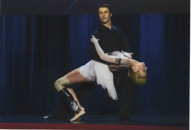
Qualitatively, the subject's dancing ability improved when using the BiOM's dance controller compared to her ability while using a traditional prosthesis. The subject was unable to perform one of the dance steps, Slow Cross Swivels, while wearing a traditional prosthesis, but was able to perform the step while using the BiOM's dance controller. This particular move requires multiple pivots ("swivels") on the toe in succession. The traditional prosthesis does not provide enough clearance, causing the heel to drag, and making the pivots much more difficult. The subject had no trouble performing this move with the BiOM's dance controller due to its plantarflexed offset. The control system was robust enough to allow the subject to complete her first public dance performance onstage at a live TED talk [8], shown in Fig. 5-1.
Chapter 6
Future Work
6.1
Limitations/Future Work
Several limitations are apparent due to the choice of a commercial powered prosthesis. The BiOM is heavier than both the biological limb and traditional prostheses. This reduces the dancer's maneuverability and causes her to expend more energy than she otherwise would.
More work needs to be done to investigate the additional stresses placed on the device while dancing. This includes the impact of dancing on battery life, as well as long-term effects of these mechanical stresses on the lifetime of the motors and other hardware components of the device. While we did not encounter any stress-based issues even during multi-hour test sessions, we also did not explicitly measure these effects.
The BiOM's range of motion is much smaller than that of the biological ankle. The BiOM provides 24 degrees of plantarflexion and 0 degrees of dorsiflexion, while a biological ankle can provide 50 degrees of plantarflexion and 20 degrees of dorsiflexion
[1]. This is suitable for the standard walking and running modes of the device.
However, this limitation means that the device cannot fully recreate the movements of an able-bodied dancer.
of bionics, capture data about the prosthesis itself, while extrinsic sensors capture data about the environment or user. The BiOM's sensors can determine the spatial orientation and forces on the device, but do not capture signals directly from the user. This means the device must infer the intent of the user without direct user input and react accordingly. The addition of extrinsic sensors could give the user more direct control of the prosthesis. Members of the Biomechatronics Group are currently researching augmenting the BiOM's walking activity mode using surface electromyography (EMG) electrodes to detect muscle contractions in the patient's residual limb [21, 2]. This same technology could be applied to a dance controller in
order to modulate stiffness.
There are many other specialized controller designs that could augment an am-putee's ability to perform those activities. The dance controller developed here ex-ploits the relative simplicity of ankle movement in the Rumba. While this controller may work for a wider range of dance styles and steps, it is unlikely that the current controller is the most robust form of dance controller. Further, what other activities beyond dancing could be enabled with specialized software in a powered prosthetic platform such as the BiOM?
The current dance control system is not yet viable for widespread use. There is currently no way to switch between the standard walking activity mode and the custom dance controller without reprogramming using specialized software. A user-friendly method to toggle controller modes must be devised to enable widespread use. More generally, a method of switching between many different activity modes would be necessary if additional specialized controllers were developed.
6.2
Impact
This study opens the door to quantifying other impactful activity modes, rather than only activities of daily living. By understanding and quantifying these activities, we can create prosthetic devices that enable amputees to become more proficient at these activities.
The success of this project implies that a powered prosthesis can enable an am-putee to perform a variety of specialized activities with minimal hardware modifica-tions to the prosthesis. Ideally, an amputee would be able to use a single robotic prosthesis with a variety of control systems for each of his preferred activities.
Bibliography
[1] MD Alex Moroz. Physical therapy (pt), September 2013.
[2] Samuel K Au, Paolo Bonato, and Hugh Herr. An emg-position controlled sys-tem for an active ankle-foot prosthesis: an initial experimental study. In
Reha-bilitation Robotics, 2005. ICORR 2005. 9th International Conference on, pages
375-379. IEEE.
[3] Samuel K Au, Jeff Weber, and Hugh Herr. Powered ankle-foot prosthesis
im-proves walking metabolic economy. Robotics, IEEE Transactions on,
25(1):51-66, 2009.
[4] G.A. Carpenter and S. Grossberg. The art of adaptive pattern recognition by a self-organizing neural network. Computer, 21(3):77-88, March 1988.
[5] Sung-Bae Cho. Neural-network classifiers for recognizing totally unconstrained
handwritten numerals. Neural Networks, IEEE Transactions on, 8(1):43-53, Jan
1997.
[6] Sorin Draghici. A neural network based artificial vision system for licence plate
recognition. International Journal of Neural Systems, 08(01):113-126, 1997.
[7] Kunihiko Fukushima. Neocognitron: A hierarchical neural network capable of
visual pattern recognition. Neural Networks, 1(2):119 - 130, 1988.
[8] Hugh Herr. Hugh herr: The new bionics that let us run, climb and dance. http://www.ted.com/talks/hugh-herr-thenew-bionicss.-thatlet usrunclimband-dance, March 2014.
[9] Hugh M Herr and Alena M Grabowski. Bionic ankle-foot prosthesis normalizes
walking gait for persons with leg amputation. Proceedings of the Royal Society
B: Biological Sciences, 279(1728):457-464, 2012.
[10] Arun D. Kulkarni. Computer Vision and Fuzzy-Neural Systems. Prentice Hall
PTR, Upper Saddle River, NJ, USA, 1st edition, 2001.
nu-[12] Marcia W. Legro and Gayle Reiber. Issues of importance reported by persons with lower limb amputations and prostheses. Journal of Rehabilitation Research
& Development, 36(3):155, 1999.
[13] Carl Grant Looney. Pattern Recognition Using Neural Networks: Theory and
Algorithms for Engineers and Scientists. Oxford University Press, Inc., New
York, NY, USA, 1997.
[14] J.P. Pell, P.T. Donnan, F.G.R. Fowkes, and C.V. Ruckley. Quality of life follow-ing lower limb amputation for peripheral arterial disease. European Journal of
Vascular Surgery, 7(4):448 - 451, 1993.
[15] Mark R Pitkin. Biomechanics of lower limb prosthetics. Springer, 2010. [16] L. R. Lower limb prosthesis, June 28 1974. US Patent 3,820,169.
[17] H.A. Rowley, S. Baluja, and T. Kanade. Neural network-based face detection.
Pattern Analysis and Machine Intelligence, IEEE Transactions on, 20(1):23-38,
Jan 1998.
[18] H.A. Rowley, S. Baluja, and T. Kanade. Rotation invariant neural network-based
face detection. In Computer Vision and Pattern Recognition, 1998. Proceedings.
1998 IEEE Computer Society Conference on, pages 38-44, Jun 1998.
[19] Thomas Schmalz, Siegmar Blumentritt, and Rolf Jarasch. Energy expenditure
and biomechanical characteristics of lower limb amputee gait:: The influence of prosthetic alignment and different prosthetic components. Gait & Posture,
16(3):255 - 263, 2002.
[20] Richa Sinha, Wim JA van den Heuvel, and Perianayagam Arokiasamy. Fac-tors affecting quality of life in lower limb amputees. Prosthetics and orthotics
international, 35(1):90-96, 2011.
[21] Jing Wang, Oliver A Kannape, and Hugh M Herr. Proportional emg control of ankle plantar flexion in a powered transtibial prosthesis.
[22] M.S. Zahedi, A.J. Sykes, and S.T. Lang. Lower limb prosthesis, February 11