-4
THE DEVELOPMENT OF A GPS ENABLED TRACKING SYSTEM
IMPLEMENTED ON A WEB SERVICES ARCHITECTURE
By
Charles Assaf
Bachelor of Engineering in Mechanical Engineering, McGill University, 2002 Submitted to the Department of Civil Environmental Engineering
in partial fulfillment of the requirements for the Degree of
MASTER OF ENGINEERING IN INFORMATION TECHNOLOGY
AT THE
MASSACHUSETTS INSTITUTE OF TECHNOLOGY
JUNE 2003
©
2003 Charles Assaf. All rights reserved.The author hereby grants MIT permission to reproduce and to distribute publicly paper and electronic copies of this thesis document in whole or in part.
Signature of Author ... Charles A saf Department of Civil and Environmental Engineering
Vay,}thMa4.9 2003 Certified by:...
obh1 R. Williams Associate Professor, Department bp&ivil & Fivironmental Engineering Thesis Supervisor
Accepted by... "w .. ...
or Oral Buyukozturk
Chairman, Department Committee of Graduate Students
BARKER
MASSACHUSETTS INSTITUTE
OF TECHNOLOGY
THE DEVELOPMENT OF A GPS ENABLED TRACKING SYSTEM
IMPLEMENTED ON A WEB SERVICES ARCHITECTURE
By
Charles Assaf
Submitted to the Department of Civil & Environmental Engineering On May 19th, 2003 in Partial Fulfillment of the
Requirements for the Degree of Master of Engineering in Information Technology
ABSTRACT
Advances in GPS (Global Positioning System) technology and wireless communication have introduced new grounds for applications in tracking systems. In addition, the rapid proliferation of the internet as a ubiquitous network to share and exchange information has created a new channel to reach clients or businesses. This has enabled the integration of disparate technologies into one system: an innovative tracking system that provides its users with a real-time monitoring method from any web-enabled device.
This thesis explores the development of a GPS-enabled tracking system implemented on a Web services architecture. Web services building blocks will be described from a technical and business perspective with special emphasis on the viable business model that can be adopted by potential Web services providers.
Thesis Supervisor: John R. Williams
Acknowledgments
First, I would like to thank Prof. John Williams for supervising the "i-track" project and giving me the guidance and encouragement I needed to complete this thesis.
I would also like to thank Emile, my father, for supporting me throughout this year and having confidence in all my decisions. I am also grateful to Samia, my mom, for her boundless love and encouragement. Many thanks also go to Albert, Celine, and Marc, my siblings, for their continuous interest and care.
Finally, I would like to acknowledge Wadih Jreissati and Loai Na'amani, fellow M.Eng. colleagues, for their insight and advice.
TABLE OF CONTENTS
1. Introduction ... 7 1.1 M otivation ... 7 1.2 i-Track ... 7 1.3 System O verview ... 7 1.4 .N ET Fram ew ork... 8 1.5 W eb Services... 9 1.6 Thesis O rganization... 92. The "i-Track" Tracking System ... 10
2.1 System Architecture ... 10
2.2 The H ardw are... 12
2.3 Softw are A rchitecture ... 13
2.4 A pplication A rchitecture ... 14
2.5 W ebsite D escription ... 15
2.6 A ctivity M odel... 16
2.7 Benefits of W eb Services Technology ... 18
3. W eb Services...19
3.1 Introduction ... 19
3.2 Service-O riented A rchitecture... 20
3.3 W eb services Standards... 21
3.3.1 X M L ... 21
3.3.2 U D D I... 22
3.3.3 W SD L... 23
3.3.4 SO A P... 24
3.4 SO A P Com m unication Paradigm ... 26
4. Im plem enting M apPoint.N et... 27
4.1 Introduction ... 27
4.2 M apPoint .NET W eb service ... 28
4.3 M apPoint .N ET Server... 29
4.4 Client A pplications... 29
4.5 D iscovering and Binding... 30
4.5.1 Searching the M apPoint.N ET W eb service... 30
4.5.2 A dding a W eb Reference to an A pplication... 33
4.6 M apPoint .NET A uthentication... 34
4.7 D ata Sources... 35
4.7.1 M aps ... 35
4.7.2 Points-of-Interest... 35
4.8 M apPoint .NET in a W eb Application... 36
4.9 M apPoint N ET Services... 37
4.9.4 Find Service... 41
5. A Business Perspective of W eb services ... 42
5.1 Introduction ... 42
5.2 Current Technologies ... 42
5.3 The W eb Services Architecture... 43
5.3.1 Technology Layer ... 43
5.3.2 W eb Services M anagem ent Layer... 43
5.3.3 Application Services Layer ... 44
5.4 Com petitive Advantage... 45
5.5 W eb Services and the Industry ... 46
5.5.1 Partner W eb Services ... 46
5.5.2 Private W eb Services ... 47
5.5.3 Public W eb Services... 47
5.6 Early Adopters of W eb Services ... 47
5.7 A W eb Service Provider Business M odel... 50
5.9 W eb Service Provider Characteristics... 52
6 Conclusion... 53
Appendix ... 54
TABLE OF FIGURES
Figure 1: System A rchitecture...11
Figure 2: The BCR M l10 Unit. ... 12
Figure 3: The Software's Architecture... 13
Figure 4: Application architecture... 14
Figure 5: Activity diagram ... 17
Figure 6: Service Oriented Architecture. ... 20
Figure 7: Web services infrastructure. ... 21
Figure 8: UDDI Information Hierarchy . ... 23
Figure 9: SOAP Message ... 25
Figure 10: MapPoint.NET Architecture... 28
Figure 11: Finding a Service page from UBR using Visual Studio .NET. ... 30
Figure 12: Advanced search from UBR using Visual Studio .NET... 31
Figure 13: MapPoint ... 32
Figure 14: MapPoint .NET Basic Services Bindings... 32
Figure 15: MapPoint .NET WSDL File. ... 33
Figure 16: MapPoint.NET Application Architecture... 37
Figure 17: MapPoint .NET map rendering Web service... 40
Figure 18: Web services Architecture... 44
1.
Introduction
1.1 MotivationThe ability to combine the power of the internet with the freedom of wireless technology in a GPS-enabled system constituted an incentive for the development of the "i-track" project described in this thesis. The main objective was to build a tracking infrastructure that could leverage different applications and provide an efficient way to locate GPS-enabled units. i-Track will serve as a tracking infrastructure built on a Web services architecture that will revolutionize the way location-based data is retrieved.
This thesis explores the development of a GPS-enabled tracking system implemented on a Web services architecture. The recent advent of Web services was also a motivation to study the viable business models that can be adopted by potential Web services providers.
1.2 i-Track
As a core requirement in the Masters of Engineering program at the Massachusetts Institute of Technology, students are entitled to pursue a yearlong project that enriches their knowledge in their area of specialization. "i-track" is an Information Technology project that was developed by three students with a common objective of exploring possibilities in the wireless communication technology as well as Web services. The following section gives an overview of the i-track project.
1.3 System Overview
i-Track consists of a tracking system that integrates wireless communication technology with the Global Positioning System (GPS) to transmit location-based information over the internet. i-Track includes two main functional components: the hardware and the software system.
Primarily, the hardware is composed of a small unit that embeds a GPS receiver, a GPS antenna, a GSM/GPRS modem, a microprocessor and a stand-alone power source. This unit relays a steady stream of data on the location of its host to ground stations. The type of data transmitted consists of latitude and longitude coordinates, which are used to generate graphical interfaces that pinpoint an exact location on a map.
Then, the software system, built on Web services architecture, incorporates windows-based GUI (Graphical User Interface). The user interface exposes the main function of the system; users can retrieve maps showing the unit's location and access location-based information in real time. In this attempt to take advantage of many technologies and join them into one system, i-Track potential applications range from remotely monitoring children to tracking lost pets and endangered species, as well as managing the supply chain of certain products and locating lost or stolen assets.
1.4 .NET Framework
The .NET framework was chosen as the platform to develop the i-Track software system. The first reason is that the .NET framework constitutes an ideal infrastructure in which Windows-based applications may be developed and run. Secondly, the .NET framework is designed for applications that expose or consume Web services, and the i-Track system leverages the Web services of MapPoint.NET.
The .NET framework consists of two major components:
1. The common language runtime that integrates classes of various languages
and provides features such as memory management, thread management, object type safety, security and other core services.
2. The .NETframework class library that provides access to system functionality. It is divided into hierarchical namespaces, where each namespace holds classes and other types that share a common purpose. The FCL is designed to
1.5 Web Services
Web services constitute a set of standards for application integration; their primary purpose is to make software functionality available over any network, while overcoming differences in technology and communication incompatibilities. Web services integrate applications at a business logic level rather than only at a system' or data level and it can be adopted incrementally via ubiquitous non-proprietary networks, such as the internet.
1.6 Thesis Organization
Chapter 1 gives an overview of the i-Track project and the main motivations behind this thesis. Then, Chapter 2 clarifies how the i-Track system functions: it describes the hardware and the software architecture of the i-Track system, and discusses the benefits of using the Web services technology. After that, Chapter 3 describes the building blocks of Web services: it explains the infrastructure onto which Web services are developed and provided a background on the Web services standards. Chapter 4 then explains how we implemented the MapPoint.NET Web service in the i-Track system. In addition, a description of the data sources and the interface of the service is provided. Chapter 5 gives a business perspective of Web services: it describes how this technology can be used to create business value and provides an assessment of the potential business model that could be embraced by Web service providers. Finally, Chapter 6 gives the summary and conclusion.
2. The "i-Track" Tracking System
2.1 System Architecture
The GPS consists of a system of satellites, computers, and receivers that are able to determine the latitude and longitude of a GPS-receiver anywhere in the world to within a few inches; this can be accomplished by calculating the difference in time for signals from different satellites to reach the receiver. To utilize GPS technology for our product, a small GPS receiver and a GPS antenna are needed to obtain readings of time, latitudes and longitudes. GPS technology is actually free and readily available in any weather condition, anywhere in the world, 24 hours a day.
In order to transmit data collected from the GPS receiver wirelessly in a wide area, the most feasible technology that is available today is the GPRS (General Packet Radio Service) telecommunication technology. In fact, GPRS is a new non-voice value-added service that allows data to be sent and received across a mobile telephone network. This technology greatly improves and simplifies wireless access to packet data networks, such as the Internet for example; it applies a radio principle to transfer user data packets in an efficient way between mobile stations and external packet data networks. The radio and network resources of GPRS are only accessed when data actually needs to be transmitted between the GPRS mobile user and the GPRS network. This data is divided into packets and then transferred via the radio and core GPRS network. Between alternating transmissions, no GPRS network resources need to be allocated. The user is only charged for transferred data.
The infrastructure, i.e. the transmission towers for this technology, has already been built and the telecommunication network covers most parts of the United States. Using a GPRS-enabled modem, information about the unit's location can be transmitted wirelessly to a central web server. The latitude and the longitude of the unit will be stored
user logs on to the website to make location queries, a Web service that can transform latitude and longitude information into a graphical display is used to generate a map of the unit-holder's location. Microsoft MapPoint.Net will be used to generate this graphical display.
i-Track will have a multi-channel service delivery; the user will be capable of accessing location-based information on the following operating systems:
" Personal Computers
" Cell phones configured with Wireless Application Protocol for Internet access. " Personal Digital Assistant (PDA)
Figure 1 clarifies the system architecture.
±7
I
1
1
I
I
II~
'I-+
/
S~iin Campulecr Laptup/
Comm TowrI
Modem -zi Serer MapPoint a ServerFigure 1: System Architecture
Internet
7Dataabase 1P
2.2 The Hardware
The principal hardware components that constitute the "Business Communication Robberechts" M110 unit (shown in figure 2) consist of the GPRS Triband Modem, the GPS board and the Processor Board; this configuration makes the latter a flexible device that can suite many different type of applications. The GSM/GPRS Triband Modem is a g18 Modem for data-, fax- and SMS- transfer in the GSM networks. From the moment, the GSM Triband Modem is booked into the providers' network the device behaves like a standard modem or a fax modem. The modem is dedicated to applications in GSM 900 and 1800 MHz-Networks; it is also suited for PCS 1900 MHz (USA). The unit supports GPRS data transfer. This means that a continuous connection can be established between any intra- and inter-network.
The main advantage of using GPRS is the great improvement in data transfer speed (up to 8 times faster as GSM data transfer). In the USA and Europe, the current available GSM networks are enabled to operate with GPRS. The GPS receiver tracks the NAVSTAR GPS constellation of satellites; then, the satellite signals received by an active antenna are tracked with 12 parallel channels and then converted to an IF frequency and digitally processed to obtain a full navigation solution of position, velocity, time, and heading.
2.3 Software Architecture
The i-Track system is built on a three-tier distributed client/server architecture as shown in Figure 3. The top tier includes a user system interface where user services (text input, dialog, and display management) reside. The MapPoint.net Web service constitutes another tier; it contains cartographic, demographic, business listing as well as other data, and communicates with the Track server as needed. The middle tier consists of the i-Track server and database; a web application is running on this layer providing a link between the Web services tier and the client interface. This web application uses the MapPoint.Net Web services in order generate maps with route directions and location-based information. The connectivity between the tiers is intrinsically different: the communication between the MapPoint.net layer and the i-Track server is done through the SOAP protocol; on the other hand, the user interface and the i-Track server communicates via the HTTP protocol.
Microsoft MapPolnt.net API
i-Track Server HTTPISOAP
HTTP Client Browser
2.4 Application Architecture
The i-Track web application is built on three logical layers. The presentation layer refers to the web application pages that were developed with ASP.NET. The middle-tier provides the communication layer between the ASP.NET Web Forms and the SQL Server database; it encapsulates all the business logic components of the web application and uses ADO.NET for data access. Finally, the data tier constitutes the repository for the attribute data that is only relevant to i-Track system such as user-related information, unit-related information, and latitude and longitude coordinates corresponding to the unit's location. All the geographic data is retrieved from MapPoint.Net automatically every time a location-specific method is invoked by the user. To locate a unit or retrieve any information related to the unit's position, the user will have to log on to the i-Track website. Figure 4 illustrates the i-Track Application Architecture.
Presentation Tier Middle Tier Data Tier
ASPnet .net Assembly
Web Forms ADO.net SQL Serer
2.5 Website Description
Users can access location-based information and retrieve maps showing the unit's location in real time. The i-Track system incorporates a user-friendly windows-based GUI (Graphical User Interface) that provides access to the main functions of the system. A collection of screenshots of the i-Track system is included in the appendix. Based on the system requirements, the user should be able to:
* Access general information about the i-Track system; this includes a description of the services and features of the system.
" Login page to authenticate the user; after successful login, the user will have to input the unit product key in order to locate his unit.
* Get a report containing all his units (in the case where the user will possess more than one unit) along with a description of each unit and a locate feature for each one of them.
" Get zoom in/out capabilities as well as the ability to navigate through the map that displays the units' locations.
* Get the nearest address relative to the unit's position. " Refresh the map for continuously monitoring the unit.
* Display the unit's position corresponding to a certain time range. This would allow the user to have an idea of the movement of a certain unit.
" Get driving directions with a map displaying the roads to be followed to reach the unit's location along with a report on the distance and the time required to get to the final destination.
" Choose between the shortest or the quickest way to the location of the unit. * Access location based information relevant to the unit's position.
" Find particular point of interest in a specified range from the position of the unit. " Update his personal information.
2.6 Activity Model
The activity model provides a description of the actions undergone by both the system and the user after logging into the website of the i-Track system. After the system has validated the user's login name and password, his units are displayed. A branching node offers two possible options (Refer to figure 5 on the next page): the map generation service and the personal information update.
Upon selecting the map generation utility, a map pinpointing the location of the unit is displayed; then, the user proceeds to choosing between getting the directions to the unit and accessing location-based information on the location of the unit. If the former option is chosen, the user enters his address and the system will present detailed routing information to reach the unit along with a map that displays the path to be followed. The user will be capable of downloading the file with the route direction or printing it directly.
The location-based information consists of an assortment of relevant places of interest in the vicinity of the unit, namely police stations, fire departments etc. This depends on the actual usage on the tracking information pertaining to the unit and the user's intentions. Finally, the user is prompted to proceed to another action on a different unit or logout.
UsE neusername
& password
Systems checks if u sename/pas sword are Dvalid [Valid username/password]
Sytem displays the units pertaining to user
\/
[Invalid usemame/password]
e' [Next selection]
user chooses to update personal information (user chooses to display location of unit
users requests route information
user request Location Based InformafiionI
uUser enter ddress
Location based information displayed
) S&ystem prompts user to make another selection/log out
[User logs-out]
2.7 Benefits of Web Services Technology
There are many reasons that make the use of Web services technology advantageous when delivering mapping functionality and location-based information; they serve as an impetus when deciding upon the suitable software technology in the i-Track system.
A special facet of the information that MapPoint provides is that it is temporal. In fact, the enormous amount of cartographic data, points of interest and demographic information need to be updated on a regular basis to keep the system current. It is much more convenient and efficient for the Web service provider, Microsoft in the case of i-Track, to manage this data on our behalf. This would help us shift from investing our resources in developing GIS solutions to building on our core competencies.
Second, the focus of i-track is to provide a tracking system infrastructure with extensive features and capabilities rather than collaborate and build applications on big client side installations. Web services are perfect conduits for "ingredient" functionality; an efficient and standardized integration of those features (through SOAP/XML) add value to our solution while not compromising the broad range of functionality we aim to deliver.
Finally, a core part of the market opportunity for i-Track is to distribute tracking services on mobile devices. This means there is a strong requirement to be able to deliver location-based information "anytime, anywhere and on any device". XML Web service technology is a great fit for this task. The following chapter will describe extensively the building blocks of Web services.
3. Web Services
3.1 Introduction
Web services are application logic exposed programmatically over the internet; they constitute a programming model for discovering, exposing, and consuming application services using standard internet technologies such as XML and HTTP. In addition, Web services are platform and language-independent, enhancing application interoperability at a level that solves most of the integration problems encountered in current distributed computing paradigms. Web services consist of a set of methods that take parameters from a caller, then, execute a specific operation, and finally, send the result back to the caller. The latter in this case could be a client on a browser, a server application, or another Web service. The difference with traditional Object Oriented Programming is that the methods are not located on the client application. The key characteristics of Web services are summarized below:
* Modularity: Operations on services are frequently implemented to encompass more functionality by an aggregation of multiple services.
* Discoverable: Services can be found at both design time and run time via the UDDI registry, not only by unique identity but also by interface identity and by service kind.
* Loosely coupled: Services connected to other services and clients use many standards allowing interoperability between systems.
* Interoperability: Service provider and the service consumer have no idea what platforms or languages each other are using.
3.2 Service-Oriented Architecture
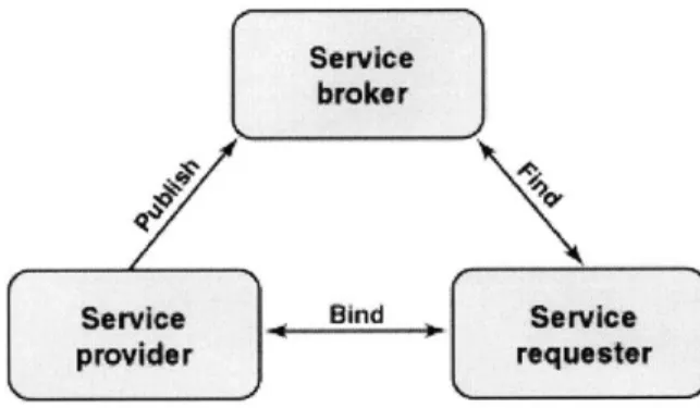
The key architectural principle underlying Web services is the Service-Oriented Architecture (SOA). The most important characteristic of an SOA is service components; they are described and organized to support dynamic automated discovery and use. SOA is comprised of three primary parties as shown in figure 6:
. Service provider: The software entity that implements a service specification; it publishes a description of the services and responds to requests to use its services. . Service broker: A specific kind of service providers that acts as a registry and
offer search services; in addition, a service broker can pass on service requests to one or more additional service providers.
. Service requester: The software entity that is responsible for discovering and invoking services; a service requestor can be an end-user application or another service.
Service
broker
Service Bind Service
provider requester
Figure 6: Service Oriented Architecture.
The service description is essential for the interaction between the different components of the SOA; it specifies the semantic characteristics of the service provider. The service broker uses this description to categorize the services in order to match them with the requester's requirement. The service description specifies the service interface that includes the available functions, the parameters, data-types, and the access protocols in
addition to various non-functional characteristics such as security, transactional requirements, cost of service, and others.
3.3 Web Services Standards
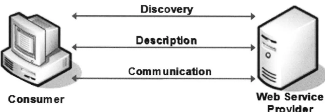
The infrastructure onto which Web services are built include a discovery system to locate Web services, a service description for defining how to use those services, and a standard communication mechanism. The following sections describe Web services standards, which include XML (Extensible Markup Language), UDDI (Universal Description, Discovery and Integration), WSDL (Web services Description Language), and SOAP (Simple Object Access Protocol).
Discovery
Defpton
Comm unication
Consumer Web Service
Provider
Figure 7: Web services infrastructure.3.3.1 XML
XML-based components make Web services applications possible. XML is a non-binary language that is used for data exchange; it provides the ability to represent data in a clear and widely accepted format that enables computers to send and receive data in a predictable style, enabling programmability that extends beyond closed and controlled systems.
XML documents are self-describing; they include both data and information about the nature of that data; a valid document contains the set of rules to which its data must
conform. In addition, XML is designed to separate syntax from semantics to provide a common framework for structuring information. Finally, XML works with existing protocols: Hyper Text Transport Protocol (HTTP) and Multi-part Internet Message Exchange (MIME).
3.3.2 UDDI
The UDDI is an online electronic registry that serves as electronic Yellow Pages with specifications that define a standard way to publish and discover information about Web services. The data stored in the UDDI registry is useful for fully automated application-to-application communication and for software-developers who wish to use the registered services. UDDI uses standard-based technologies, such as common Internet protocols TCP/IP (Transmission Control Protocol/Internet Protocol), HTTP, and XML.
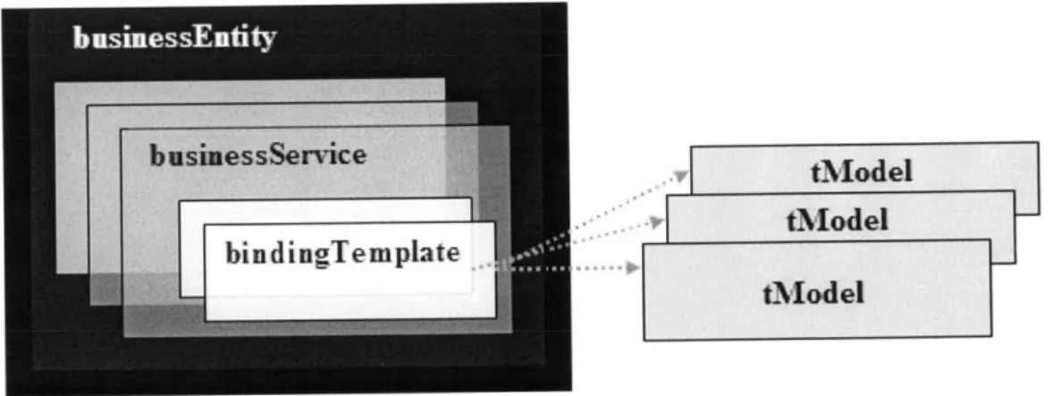
UDDI defines a 4-tier hierarchical XML schema that provides a model for publishing, validating, and invoking information about Web services. There are two types of UDDI registries: the public UDDI registries that serve as aggregation points for a variety of businesses to publish their services, and the private UDDI registries that serve a similar role within organizations. A UDDI Business Registry allows businesses to locate information programmatically about exposed Web services.
The data in the UDDI registry is structured in the following manner.
* businessEntity: It includes relevant information a bout a business service including its name, industry or product category, geographic location, and optional categorization and contact information.
" businessService: A sub-structure of the businessEntity information. The businessService describes and aggregates related Web services. The groups are relative to which category of services or business processes the Web services
" bindingTemplate: A logical child of a businessService data structure; it provides a technical description of Web services, which is relevant for applications that need to invoke or communicate with a remote Web service.
* tModel: Every bindingTemplate includes a list of references called tModels that are used to access information about the interface specifications for a service. tModels represent technical specifications like wire protocols, interchange formats and sequencing rules.
The information hierarchy used to describe and to discover Web services is shown in figure 8.
K
vl
tModeltModeltMadel
Figure 8: UDDI Information Hierarchy.
3.3.3 WSDL
WSDL is an XML-based language for describing the signatures of Web service interfaces and their locations. Programmers or automated development tools can create WSDL files and make them available over the Internet. Client-side programmers and development tools can use published WSDL descriptions to get information about available Web services and create proxies that communicate with available services. The WSDL file describes the format that the client must follow when requesting an operation. WSDL is
extensible to allow the description of services and their messages regardless of the message formats or the transfer protocols used in the communication. With WSDL, the generation of proxies for Web services is automated in a truly language - and platform
-independent way.
The WSDL file is composed of the following five key elements:
1) The <types> element is used to define the data types in the exchanged messages. 2) The <message> element describes the messages being transmitted.
3) The <portType> element describes a set of operations and the messages involved with each of these operations that refers to an input message and output messages. 4) The <binding> element identifies the protocol and data format specifications for
the operations and messages defined by a particular portType.
5) The <service> element is used to aggregate a set of related ports.
3.3.4 SOAP
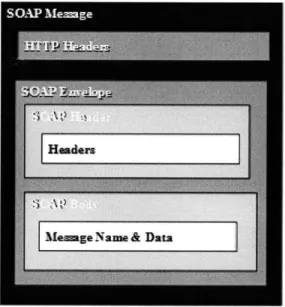
SOAP is a lightweight, XML-based protocol for exchanging information in a decentralized, distributed environment. A SOAP message consists of a SOAP envelope that includes two data structures: the header and the body; in addition to information about the namespaces used to define them. The header is optional; it is used to complement the information in the request defined in the SOAP body that contains a Web
service request or response in XML format.
SOAP supports different techniques of information exchange, RPC (Remote Procedure Call), which allows for request-response processing where an endpoint receives a procedure-oriented message and replies with a correlated response message, and
SOAP messages, when used to carry Web service requests and responses, conform to the WSDL definition of available Web services. WSDL define the SOAP message used to access the Web services, the transfer protocols by which messages can be exchanged, and the access point of these Web services.
Figure 9 describes the SOAP message format in the case where HTTP is the protocol for transferring data over the internet. The SOAP envelope containing the XML data is part of the HTTP header.
Fieure 9: SOAP Message.
The process that take place when a invoking a Web service method is similar to the one that occurs when invoking a regular method. The main difference is that the method called could be located on any remote machine. The SOAP specification provides a standard way to encode requests and responses; it describes the structure and data types of message payloads using XML Schema. Since the Web service method can be located on a different computer, the SOAP message must be passed across the network to the server that hosts the Web service.
3.4 SOAP Communication Paradigm
The following section illustrates the process of communication between a client and an XML Web service and the way that SOAP is used for the message and response of a Web service.
. A new instance of the Web service proxy class is created on the client machine. . The client invokes a method on the proxy class, the SOAP client uses an XML
document that matches the SOAP specification and contains a request for the service.
. A SOAP message is sent over the network to the Web service using the SOAP protocol.
. The Web service receives the SOAP message, and dispatches the message as a service invocation to the application providing the requested service.
. The return value and output parameters are sent in a SOAP message again using the SOAP protocol back to the client machine.
. On the client computer, the SOAP message is processed and the return values and output parameters are passed to the instance of the proxy class.
4. Implementing MapPoint.Net
4.1 Introduction
MapPoint .NET is a programmable XML Web service developed and hosted by Microsoft. MapPoint .NET enables developers to integrate location intelligence and mapping capabilities into consumer and enterprise applications while providing them with full programming control.
Web services technology revolutionized the process of including location functionality in any solution. In fact MapPoint NET combined location and mapping data into a single, subscription-based Web service, that is platform- and language-independent. This has eliminated the cost of data management and the effort invested in GIS tools that only focused on the creation of cartographic data.
MapPoint .NET has a rich API (Application Programming Interface) that provides the same functionality in all supported geographic areas while using standards such as SOAP, XML, WSDL and UDDI.
MapPoint .NET constitutes a platform for location-based services; it can be used by mobile applications to provide the following core functionality based on latitude and longitude coordinates, addresses or geographic entity types.
" Driving directions
" Display detailed and easy to read maps " Find and validates addresses and places " Find geographic entities
" Perform proximity searches for points of interest
" Find particular point of interest in a specified range from a center point " Geo-coding
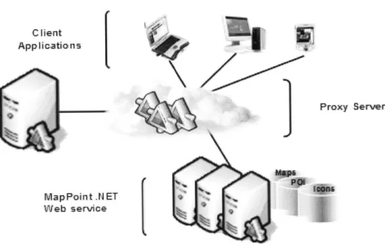
The MapPoint NET platform is a multi-tiered solution. It includes the MapPoint .NET Server that, the MapPoint .NET Web service, and the Client Application. This is shown in figure 10. C I lent App Ii-catio n s
r
Proxy Server MapPoint .N ET Web service(
Figure 10: MapPoint.NET Architecture.
4.2 MapPoint .NET Web service
This Web service, hosted by Microsoft, contains cartographic, demographic, business listing, construction, traffic and other data. Developers can incorporate those services in their applications in order to gain access to this information.
4.3 MapPoint .NET Server
This server is a proxy for the MapPoint NET Web service, hosted inside the customer application or server. It provides additional local functionality that allows applications within the customer network to request users' locations and manage privacy and permissions. The MapPoint .NET Server communicates as needed with the wireless carrier network and with the MapPoint .NET Web service.
4.4 Client Applications
Client applications reside on client machines such as desktop, laptop, or handheld devices. They constitute the front end for the Web services and accept inputs from clients. Users can access the GUI (Graphical User Interface) and take advantage of all MapPoint.NET functionality without having any knowledge of programming.
4.5 Discovering and Binding
4.5.1 Searching the MapPoint.NET Web service
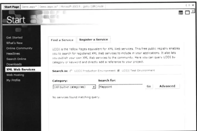
In order to use the MapPoint .NET Web service a web reference should be incorporated in the application. As a first step, the UDDI (Universal Description, Discovery and Integration) is used in order to locate the appropriate service. Using Visual Studio .NET, one can simply go to the "XML Web services" section located in the start page (Figure
11) and click on "Advanced" in the "Find a Service" section.
mid a Servict, ",~isIr, a Servi r.
K r~j~ ~ '~ ru . a~ ~ leL ~~~~~~ ~ P> fl~ t ~ L :- i ~~~~' 1 e t I :eavrh on-, r-Calegorysearch for A 7I -- i~r az Ye 1 P,
-Figure 11: Finding a Service page from UBR using Visual Studio .NET.
GO
Advitited 14 - -'r, tOnce directed to the "search criteria" page, one can input the service name of interest (Figure 12). In our case, "MapPoint" is the keyword to search the UBR (UDDI Business Registry), a global public directory of businesses and services. The result would be a complete description of the service that is constituted of the details, the bindings and the categories of the service (Figure 13).
u:ddi
77r1r4
search
- Ii'
tA I
Figure 12: Advanced search from UBR using Visual Studio .NET.
The Binding provides the relevant information where a specific implementation of a service can be accessed. It is composed of three parts: Access Point, URL Type, and the Binding Key. The Access Point constitutes the URL path to the WSDL file of the
- ~ ~ ~ ~ ai sore~ ~ (O ngodA
Search MpPint .NE T Bai S Srerie
Mw45~
~ ~~rvr -Ksinsaedyew
--- rpsmme i ---
----n~
Figure 13: MapPoint .NET Basic Services
I-4wuwt
U00L
s4ry
(tAa)
eod.e
uddi.
i
Ok*i
Iy~
#tjjmt IK-h ,t k g!!Au~
4
ree
d
00e6
4.5.2 Adding a Web Reference to an Application
The web reference connects our web application to the MapPoint.NET Web service. The WSDL (Web Service Description Language) file contains information about the interface, and the semantics to call a Web service; it describes protocols, operations, parameters, and return values. The document is written in the XML language and is used to generate proxy objects so clients can easily consume the service. Once the access point is identified, we may add a web reference to our project to use the MapPoint .NET methods
as web classes. The figure 15 below is a snapshot representation of the WSDL file.
iip is r ped hr0*.i ryg m tI rei rq w.nrJI liflg /' t n S/ I Pt Ai 1j rM"ts
ti 2 h in n110 p r i n- inf
blip: // PmMppont. net/mappoit. ?h0/
h * hI r n attl flp ii ?w w rIl
http f/s iapvolnl net/vappomnt 20/
CAetverhnlntoI
a GeVersnnl espse
viD: A y fVe11 vnInIo *1
4.6 MapPoint .NET Authentication
MapPoint .NET uses the HTTP Digest Access Authentication Scheme to authenticate the calls made to the SOAP APIs. A free evaluation account was set-up in order to gain access to the MapPoint.NET Web service. In order to establish a connection with MapPoint.Net, the middle-tier component (the i-Track application) requires the necessary connection information to connect to the Web service. A connection string is used to provide the connection information to MapPoint.Net; it needs to be supplied to the connection object every time a web-method is called. The connection string can be placed in the Application-Settings section of the web application's configuration file: "web.config" (located in the root of the web application's virtual directory). This would avoid recompiling the solution every time the password is changed while not compromising the performance of the application since the string is cached and retrieved from the web.config only when there is a change. Here is the code sample in C# that is used to authenticate the user in order to utilize the Render Service in MapPoint.NET. This code was written in the "Global.asax"; and this file contains code for responding to application-level events raised by ASP.NET or by HTTP modules.
// Create and set the logon information NetworkCredential ourCredentials = new
NetworkCredential (ConfiguraticnSetting5 .Appettings ["UserName"l,
ConfigurationSettings.AppSettings ["Password"] )
/ Create the render service, pointIng at the correct location
renderService = new MapPointService .RenderServiceSoap 0;
renderService .Credentials = ourCredentials;
renderService .PreAuthenticate = true;
4.7 Data Sources
Almost all the methods in the MapPoint.NET make use of data sources; they constitute the foundation on which all the MapPoint.NET functionality is based. In fact, Data sources can be divided into three categories based on the sort of information they enclose; namely, maps, geographic entities, addresses, routing data, point-of-interest information, and images. This section provides details about each of these categories.
4.7.1 Maps
The map data-sources contain geographic data, and they are used to render maps in a number of different styles and languages. The map data sources are divided into four categories: Europe, North America, World, and Moon maps; the first three contain geographic entities such as airports, police stations, historical sites, and parks. In addition, Europe and North America maps contain street address and routing data for a number of countries or regions; they can be used to find addresses and calculate routes.
4.7.2 Points-of-Interest
The Points-of-Interest data sources include information about a tremendous number of businesses and organizations in several countries or regions in Europe and North America. For a set of latitude and longitude coordinates, these data sources may be used to locate
specific points of interest within a specified distance of a certain location. The information returned in the results can then be used with the map data sources to find addresses, calculate routes, and render maps. There is 35 point-of-interest data sources in MapPoint.NET all organized by Standard Industry Code (SIC).
4.7.3 Icons
The icon data source is composed of an assortment of images that are handy to show a certain point on a map. The icon images returned in the results can then be used with the
4.8 MapPoint .NET in a Web Application
This scenario demonstrates the sequence of steps taken by the system when a user is accessing the i-Track site to locate a unit.
1 The Web application prompts the authenticated end-user to select the unit for which the location information is requested. The web page contains a button (Get-Map) that once clicked, a request via HTTP Post is sent.
2 The i-Track server takes the information that the end-user posts and passes it to the appropriate method of the" Render-Service" SOAP class in MapPoint .NET.
3 A URL to the map's image is returned along with additional information about the map in a SOAP response message. This will be used in the HTML when displaying the map.
4 The i-Track server then generates HTML that uses the URL and sends it back to the client.
5 The client's browser renders the HTML, and when it gets to the IMG tag with the URL, it asks for the ".gif' file from MapPoint .NET directly.
6 MapPoint .NET returns the image and the Web page is complete.
7 The MapPoint .NET servers actually generate the map and then cache the .gif file until the client uses the URL to get the map.
The following diagram (figure 16) shows the typical interaction of the client (the end user's Web browser), the i-Track server and MapPoint .NET for this scenario.
AP Request
HTTP Post 4 URL of
SOf Map
Map3
5 Map Request <MG> tag
6 GIF
Figure 16: MapPoint.NET Application Architecture.
4.9 MapPoint .NET Services
MapPoint .NET is comprised of four constituent services: Common, Find, Render, and Route services; every one of which has a corresponding class that is used in SOAP headers. Route services constitute an optional element of the SOAP Envelope. SOAP headers offer a way for delivering data to and from an XML Web service method in the case where the data is not directly related to the Web service methods. In addition, they typically contain information processed within a Web server. In MapPoint.NET, two headers are used for each service, one for customer-defined transaction logging, and one for setting the context-related information that defines the locale, language, and unit of measurement. The following C# sample code was used to set the language before calling a method.
//Declare header variables
UserInfoFindHeader myUserInfoFindHeader = new UserInfo~indHeader (;
UserInfoRouteHeader myUserInfoRouteHeader = new UserInfoRouteHeader o;
Culture Info myCultureInfo = new CultureInfo (;
//Set thle lanaauage to English before calling the method
myCultureInfo.Name = "en"
myUserInfoFindHeader. Culture = myCultureInfo;
findService .UserInfoFindHeaderValue = myUserInfoFindHeader;
Code Sample 2: SOAP Headers in MapPoint .NET
The following sections describe the methods of each of the four Web services that were used in the development of the i-Track software system.
4.9.1 Common Service
The Common service contains classes, methods, and properties that are common to the Find, Route, and Render services.
The following describes the Common service options:
. "GetCountryRegionlnfo" returns the country or region name, latitude and longitude coordinates, codes, and language for a specified region.
. "GetDataSourcelnfo" returns the functionality and name of a specified data source.
. "GetEntityTypes" returns the entity types and their corresponding properties contained in a specified data source.
. "GetGreatCircleDistances" returns an array of great circle distances, in decimal degrees, between specified points.
. "GetVersionInfo" returns the descriptive name and the related version number of the current version of the MapPoint.NET service.
2. "ParseAddress" parses a specified address string and returns an Address.
4.9.2 Render Service
The Render service allows you to render maps of routes and found locations, place pushpins, set the map size and map view, select points on a map, get location information about points on a map, pan and zoom a rendered map, and create clickable maps. The Render Service methods (figure 17) are:
. "GetMap" returns a map image, a map view, and hot area definitions based on map options.
. "GetBestMapView" returns the best map view for a selected location or set of locations. The best map view is the largest scale map that contains all the desired locations.
. "ConvertToLatLong" converts pixel coordinates to latitude and longitude coordinates on a specific map, thereby returning the latitude and longitude for
a pixel on a rendered map.
. "ConvertToPoint" converts latitude and longitude coordinates to pixel coordinates on a specific map, thereby returning the pixel coordinates for a
j* LMWW Q04 e4W~-4t 4', ~evm e e F0 'Dm rOVI-anderw rvice --- -- ------ --- ---r ov V1
Figure 17: MapPoint .NET map rendering Web service.
4.9.3 Route Service
The Route Service allows you to generate routes, driving directions, and calculated route representations (used to render a highlighted route on the map) based on locations or waypoints; set segment and route preferences; and generate map views of segments and directions. The Route Service methods are:
* "CalculateRoute" returns a route based on route segments and specifications. * "CalculateSimpleRoute" returns a route based on specified waypoints.
4.9.4 Find Service
The Find service allows you to locate addresses, geographic entities, latitude and longitude coordinate, and points of interest from MapPoint .NET data sources, as well as parse addresses and return location information for a specified latitude and longitude coordinate .The following describes the methods of the Find Service:
3.
"Find" returns a list of found places based on search options, in the order of how well the results match the search criteria.4. "FindAddress" returns a list of found addresses based on search options, in the order of how well the results match the search criteria.
5. "FindNearby" returns a list of found points of interest based on entity type, in the order of proximity to a selected point.
6.
"GetLocationInfo" returns a list of addresses and geographic entities at a specified latitude and longitude coordinate within a specified data source.5.
A Business Perspective of Web services
5.1 Introduction
The intent of this chapter is to model how Web services can be used to create business value in today's enterprises. A comparative approach is applied to get an understanding of the benefits of Web services in business processes. In addition, the competitive advantage gained by companies leveraging this technology is portrayed from an external and internal perspective. Finally, an assessment of the potential business model that could be embraced by Public Web services providers is considered while emphasizing the challenges and obstacles such companies may face in the future.
5.2 Current Technologies
As companies face increasingly complex channels of customers and suppliers, the application integration challenge will be one of the most important IT challenges in the future. Many limitations still exist in present technologies; collaborative methods regularly used for application integrations are in fact very expensive to integrate. In addition, current Enterprise Resource Planning (ERP) systems are inflexible, despite the fact that they link different applications in companies and centralize their information systems; they restrain companies into a rigid business process that is ERP-centric. Consequently, it becomes difficult for companies to adapt rapidly to changes in their environment limiting their reach to new partners and customers in the supply chain.
Web services can be differentiated on many levels from previous technologies. In order to clarify the overall schema of this technology, the Web services architecture is elaborately described.
5.3 The Web services Architecture
The Web services architecture is built on three logical layers (refer to figure 18).
5.3.1 Technology Layer
This layer serves as an infrastructure for Web services creation, deployment and interaction; it consists of a set of standard technologies and communication protocols that provide the road for data exchange between different applications and organizations.
5.3.2 Web Services Management Layer
The idea behind Web services management is to provide a business-oriented management and monitoring environment that enables the enterprise to optimize the delivery and consumption of Web services within their business processes. This will allow organizations to handle a Web service as a business resource in a reliable and well-trusted environment. Companies that are looking to employ Web services will need to manage those services across key functions. The following are the key utilities of the Web services management layer:
* Security: provides authorization and authentication services that allow requestors to access particular Web services based on business-specific credentials.
" Business Activity Monitoring: provides managers with real-time access to critical business performance indicators in order to see when services are being used, by
whom, and for what business-oriented purposes.
" Performance Auditing: gives the user the assurance that the agreed-upon quality of service and service level agreements will be achieved.
" Revenue Management: provides a way to manage the commercial aspect of Web services as the aggregation of charges and the monitoring of payments.
" Orchestration: coordinates the different Web services that are used for particular business processes. This will achieve flexibility and responsiveness on a dynamic basis.
* Directories: manages the resource knowledge of Web services. The directories describe available application services and illustrate the right way to interact with them.
5.3.3 Application Services Layer
This third layer includes the different application services that are exposed in particular business processes. Those applications services may be deployed for internal or external use; they can perform functions ranging from simple requests to complicated processes. Furthermore, they all rely on the Technology and Web services Management layer to execute efficiently. Figure 18 illustrates the Web services architecture layers:
5.4 Competitive Advantage
The Web services architecture has distinctive rewards; the companies that will adopt this technology will gain competitive advantage by utilizing their information systems more effectively.
A fundamental facet of the Web services architecture is modularity. In fact, the ability to purchase only the required functionality will substantially reduce IT investments. Enterprises will start by migrating from small systems that involve minimal costs and risks while leaving issues that are more delicate to evaluation because executive management gain trust in the functionality of Web services technologies. As a result, the IT development staff will spend less time maintaining multiple interfaces and protocols, which will facilitate a more business-centric focus.
This in turn will improve IT efficiency by allowing enterprises to focus on their core competencies while integrating other application services from specialized providers. Web services architecture relies on standardized technology that facilitates outsourcing activities and processes. In addition, the risk of using obsolete technologies is reduced since companies offering services will constantly need to update their technologies in order to compete in a market where the entry barriers are low.
Another important advantage in Web services architecture is loose coupling. Communication between different systems is achieved more effectively by sharing the same standards for data description and connection protocols. Regardless of being located internally or externally, enterprise applications can communicate seamlessly with other applications without substantial investment in migration programming and point-to-point integration connectors. This flexible collaboration between previously disparate systems will provide organizations the capability of using their information more efficiently in addition to sharing their resources with business partners.
Finally, the ability to complement existing systems with Web services allows companies to expose their services so that they can be discovered and accessed by other applications. This creates a new source of revenue for the service provider based on a pay-per-use model. For the service requestor, the process becomes an aggregation of information and interactions; companies can get their legacy mainframe applications to communicate with brand-new Web-based systems.
5.5 Web Services and the Industry
The consumers and providers of Web services applications connect over a network. The network can be an intranet that links the internal systems of an organization, an extranet that connects an organization to outside partners, or the Internet. Consequently, Web services can be divided into three distinct categories: partner, private, and public Web services. Enterprises will use each category based on the characteristics of their particular industry.
5.5.1 Partner Web Services
Partner Web services links customers, partners and remote business units. This connectivity will facilitate the information flow between multiple tiers of supply chain partners. Highly fragmented industries with complex products will benefit from the use of partner-centric Web services through improvements in the supply chain management. In fact, in the computing and electronics industry, companies will exchange live supplier and producer data to manage effectively their inventory and cash flow. Similarly, for the motor vehicles industry, large car manufacturers will enhance their manufacturing and
5.5.2 Private Web Services
Private Web services are primarily used for integration within an enterprise; they provide a standard for internal applications integration and data aggregation of services. Industries that rely on numerous internal systems and legacy applications will benefit from private Web services through low-cost application-to-application connections. The financial services industry will use private Web services to link complex data sources and customer channels to a centralized application. Likewise, the telecom industry will use private Web services to assemble services for customers from a single location.
5.5.3 Public Web Services
Public Web services will provide a directory to discover new partners and collaborate on a real-time basis. Web services providers will expose their application programming interfaces on the internet to engage with new partners in need of specific functionality. Industries characterized by short product life cycles, short-term engagements, and low entry barriers will adopt public Web services for dynamic business relationships. Marketing and consulting services will use public Web services to exposes their business services in order to be found by clients. As for the transportation industry, the usefulness of public Web services will be in the capability to manage shipping capacity in real time.
5.6 Early Adopters of Web Services
As Web services start to infiltrate enterprise IT projects, the versatility of this technology is becoming gradually more apparent. Numerous companies have adopted Web services internally as a data integration catalyst or externally as a new channel of revenues. The enhancements achieved by the early adopters of Web services are discussed in this section.
Dell and its partners operated on disparate systems making information sharing very labor intensive. Dell used to carry inventories of up to 30 hours in its factories as a buffer against unexpected disruptions in the supply chain.
The challenge of imposing a common technology platform between Dell and its suppliers has been circumvented by the use of Web services. As a result, the adoption of this technology has enabled Dell to manage efficiently their supply chain, cutting inventory buffers from 30 to 5 hours and improving cost efficiencies by pulling materials from suppliers that are tied to customer orders. Dell also used Web services to provide suppliers with forecasting information and to gather information about the suppliers' ability to meet the forecasts. In addition, information about availability, capacity, and engineering changes, as well as inventory data, flows both ways between Dell and its
suppliers.
Danske Bank, a Copenhagen-based financial institution, adopted a Web services approach by building a common platform that facilitates functionality integration across its disparate systems. This was achieved through a portal system that enabled customers and 7,000 financial advisers to access information drawn from the different back-end systems. The system aggregated customer information, product information, and real time market data analysis. As a result, it became possible for employees to access a unified customer-purchase record and correspondence history from the same interface, without having to call individual systems one at a time.
Rotech Healthcare operated through numerous data centers with disparate product collections grouped in a way to provide specific services. Rotech's objective was to make information available across storefronts and servers without having to maintain redundant data stores or perform complicated synchronizations. Rather than building custom connections between components, Rotech opted for Web services to link the disparate sources. The use of Web services has improved the analysis that may be performed with the data from a unified point of access.