Development of Dielectric Elastomer Actuators for MRI Devices by
John D. Vogan BS Mechanical Engineering Case Western Reserve University, 2002
Submitted to the Department of Mechanical Engineering in Partial Fulfillment of the Requirements for the Degree of
Master of Science in Mechanical Engineering at the
Massachusetts Institute of Technology June 2004
@2004 Massachusetts Institute of Technology All Rights Reserved
Signature of Author. ,.. ... ..
Department of Mec i cal Engineering May 7, 2004
A
-/
Certified by. . . . . . .. . . . ... .
Steven Dubowsky
Professor of Mechanical Engineering Thesis Supervisor
Accepted by ... ...
Ain A. Sonin
Chairman, Department Committee on Graduate Students
MASSACHUSETTS INS E OF TECHNOLOGY
LIBRARIES
Development of Dielectric Elastomer Actuators for MRI Applications by
John D. Vogan
Submitted to the Department of Mechanical Engineering on May 7, 2004 in Partial Fulfillment of the
Requirements for the Degree of
Master of Science in Mechanical Engineering
ABSTRACT
Dielectric elastomer (DE) actuators are an emerging class of polymer actuation devices. They exhibit large strains and have high force and energy densities. They can be designed in a variety of geometries and are inexpensive to manufacture. Currently, the use of DE Actuation is limited because quantitative design information is incomplete and the complex phenomena governing their performance have not been fully characterized. In this study, several such issues are investigated both experimentally and analytically.
The actuators designed for this research function as binary actuators, that is, they operate between two set states, OFF and ON. Performance of the actuators is predicted based on theoretical analysis and the results are compared to experimental results. Improvement of fabrication methods and determination of optimum design parameters
have been experimentally determined.
Since DE actuators can be constructed out of polymers and without any ferromagnetic materials, they can potentially be used in a Magnetic Resonance Imaging (MRI) machine, which has strict compatibility requirements that limit the use of certain materials. MRI is a powerful and effective medical diagnostic tool, but treatment is limited because of the confined space and compatibility issues. It has been well recognized that its value would be increased if it were possible to physically manipulate objects within the MRI machine during imaging, but conventional manipulation systems cannot operate within an MRI due to the incompatibility of ferromagnetic materials.
Binary DE actuators eliminate the need for conventional electromagnetic actuators and their associated controlling electronics. This inherent compatibility suggests that a new class of MRI treatment devices is possible. Potential applications for use in the MRI environment are introduced, and prototypes for illustrating these applications are fabricated. One such application, a reconfigurable RF coil for flexible imaging capabilities, proves that not only are DE actuators and MRI compatible, but that they can significantly enhance imaging capabilities.
Thesis Supervisor: Steven Dubowsky Title: Professor of Mechanical Engineering
Acknowledgements
This research was performed at the Field and Space Robotics Laboratory (FSRL) at MIT under the sponsorship of the Center for Integration of Medicine and Innovative Technology (CIMIT) and Cambridge MIT Institute (CMI).
I would like to thank my advisor Professor Steven Dubowsky for his guidance and the opportunity to work at the FSRL. Thanks to Vivek Sujan, Karl Iagnemma, and Sauro Liberatore for their valuable supervision and advice. Thanks to all members of the FSRL, especially Jean-Sebastien Plante for his valuable help in developing many of the ideas and devices presented in this work. His experience and involvement was invaluable. Thanks to Dan Kacher at Brigham and Women's Hospital for his collaboration with the MRI experiments and applications.
I would also like to thank my family and especially my wife, Brianne, for their support over the past two years.
Table of Contents
Abstract... 2
Acknowledgem ents ... 3
Table of Contents... 4
Figures and Tables... 6
1 Introduction ... 8
1.1 M otivation... 8
1.2 Background and Literature ... 10
1.2.1 Dielectric Elastomer Actuation and alternative Technologies... 10
1.2.2 Actuation within M RI M achines ... 12
1.3 Research Overview ... 13
2 Fundamental properties of Dielectric Elastomers... 15
2.1 Operating Principle ... 15
2.2 Actuator Com ponents ... 16
2.3 Elastom er Characterization and Selection ... 19
2.4 Film Failure... 22
2.4.1 Failure m odes... 22
2.4.2 Dielectric Strength M easurem ents... 23
2.4.3 Film Quality ... 24
2.4.4 Electric Field Concentrations... 33
2.4.4.1 Analytical Developm ent ... 34
2.4.4.2 Results... 38
2.4.4.3 Discussion ... 45
2.4.5 Electrical Fatigue ... 47
3 Linear Actuator Design... 49
3.1 Film Design for Actuators ... 49
3.2 Fram e Design ... 51
3.2.1 Geom etry Selection... 51
3.2.2 Structural Design ... 55
3.3.1 D evice Selection - "Negator"... 58
3.3.2 D efining N egator Param eters... 65
3.4 Linear A ctuator Perform ance... 70
4 M RI A pplications ... 73
4.1 Reconfigurable Surface Coil... 73
4.1.1 Coil D esign ... 75
4.1.2 Results... 76
4.1.2.1 Com patibility ... 77
4.1.2.2 The Single Actuator Integrated Coil D esign... 78
4.1.2.3 Multi-Actuator Modular Coil Design Concept ... 79
4.1.3 D iscussion ... 81
4.2 M anipulation Applications... 82
4.2.1 Linear Positioning... 82
4.2.1.1 Specifications... 83
4.2.1.2 D esign and Prototype... 84
4.2.2 Bi-Stable M anipulator D esign ... 87
4.2.2.1 Bi-stable M odule... 90
4.2.2.2 Binary Stage... 93
5 Conclusion... 96
5.1 Sum m ary of Results... 96
5.2 Future W ork ... 96
5.3 O utlook ... 98
Figures and Tables
Figure 1: Operating principle of dielectric elastomer ... 10
Figure 2: Maxwell pressures acting on elastomer... 15
Figure 3: Three basic arrangements for DE actuators. ... 18
Figure 4: Lumped sum model of actuator system... 18
Figure 5: Dielectric properties of candidate DE materials... 20
Figure 6: Maximum pressure for potential dielectric materials... 21
Figure 7: Maximum potential strain for candidate elastomers ... 21
Figure 8: V arious failure m odes. ... 22
Figure 9: Simple model of a void within a dielectric... 25
Figure 10: A single imperfection in a piece of VHB film, magnified at 100 and 400x... 27
Figure 11: Breakdown testing for two different cases, both over and isolated from visually detected im perfections. ... 28
Figure 12: Failure voltage from electrodes both adjacent to and far from visual im perfections. ... 28
Figure 13: Microscopic inclusions or void. ... 29
Figure 14: Failure voltage from electrodes both adjacent to and far from microscopic im perfections. ... 30
Figure 15: Experiment showing no correlation of breakdown strength to adjacency to fram e ... 3 3 Figure 16: Schematic of 3-dimensional electrostatic model... 35
Figure 17: Two-dim ensional space... 35
Figure 18: The charge at a single point (darkly shaded) can be computed by averaging the potentials at the points adjacent to it (lightly shaded). ... 36
Figure 19: Potential field ... 39
Figure 20: Potential field over the x-z plane... 40
Figure 21: Plot of electric field at several depths within the dielectric. ... 41
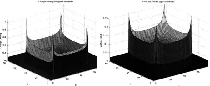
Figure 22: Charge distribution and electric field at the surface of an electrode ... 43
Figure 23: Example of an irregularity on the edge of an electrode. ... 43
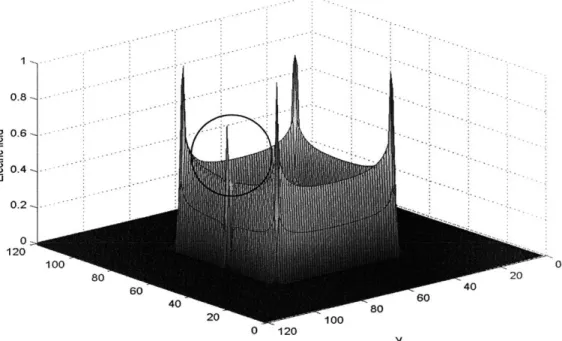
Figure 24: Electric field over a square electrode with an irregularity at its edge. ... 44
Figure 25: Experimental setup for determining quantitative value of edge effect. ... 44
Figure 26: Comparison of breakdown strength for both sharp and round electrodes... 45
Figure 27: Dielectric failure limited to small regions... 46
Figure 28: Film with special geometry for eliminating field concentrations... 46
Figure 29: Maximum area expansion as a function of pre-strain expansion. ... 50
Figure 30: Parallel beam actuator ... 51
Figure 31: Bowed in effect due to high pre-strain ... 52
Figure 32: Monolithic frame with complete border... 52
Figure 33: General dimensions for hexagonal frame... 53
Figure 34: Maximum achievable strain values as a function of frame geometry... 54
Figure 35: Current fram e design ... 55
Figure 36: Frame using inherent stiffness of flexures for restoring force. ... 56
Figure 37: Decreasing blocked force due to stress relaxation. ... 57
Figure 39:Experimental stiffness profiles for film/frame assembly at various voltages.. 60
Figure 40: Stiffness profiles for two common types of pre-load elements... 61
Figure 41: Stiffness profiles for pre-load element with negative spring constant. ... 62
Figure 42: Previous version of device with negative spring constant. ... 62
Figure 43: Schematic of negating element using elastic elements. ... 63
Figure 44: Model of negating element compared to experimental data. ... 64
Figure 45: Example of a desired curve compared to randomly generated curve... 67
Figure 46: Experimental ON and OFF curves and their weighted average... 68
Figure 47: Target and derived curves. ... 69
Figure 48: Frame design with fixturing holes incorporated into it. ... 70
Figure 49: Actuator in ON and OFF state... 70
Figure 50: Force, current, and voltage profiles for actuator. ... 71
Figure 51: Basic operating principle of an RF coil... 74
Figure 52: Single actuator, concentric coil design concept. ... 75
Figure 53: Multiple linear actuator design concept. ... 76
Figure 54: Possible configurations the multiple actuator concept... 76
Figure 55: Imaging results for conventional imaging coil alone and imaging coil with actuated DE actuator directly beside it... 77
Figure 56: Conventional copper coil and a DE based coil of similar dimensions with their acquired im ages. ... 78
Figure 57: Resizable copper frame with the DE in both the OFF and ON position... 80
Figure 58. Imaging results for multiple actuator design. ... 81
Figure 59: Schematic of Focused Ultrasound Surgery ... 82
Figure 60: Current Focused Ultrasound Surgery system... 83
Figure 61: Inchworm concept, showing motions of clamping assembly... 85
Figure 62: Illustrative prototype of inchworm concept. ... 86
Figure 63: Surgical assist robotic system ... 87
Figure 64: BRAID III ( actuated by DE actuators) and a theoretical workspace. ... 89
Figure 65: Theoretical design of BRAID with current actuator performance... 89
Figure 66: Bi-stable structure, water jet cut out of 1/8" thick Delrin. ... 90
Figure 67: FEA model of one horizontal bar of bi-stable structure... 91
Figure 68: Alternative loading positions for bi-stable structure. ... 91
Figure 69: Symmetric bi-stable module, actuated by antagonistic DE actuators. ... 93
Figure 70: Bi-stable, multiple degree of freedom stage... 93
Figure 71: Potential configurations for bi-stable structure. ... 94
Figure 72: Alternative arrangement for actuators and bi-stable element ... 95
Table 1: Smart Material Actuator Comparison [21]... 11
Table 2: Statistical analysis of failure data (breakdown voltage)... 31
Table 3: Decoding of binary string into parameters values ... 66
Table 4: Parameters generated by algorithm for designing negator element...70
Table 5: Actuator performance characteristics ... 72
Introduction
This thesis reports on the development of dielectric elastomer (DE) actuators for use as an actuation technology within Magnetic Resonance Imaging (MRI) environments. Dielectric elastomers are a type of electroactive polymer that has shown significant potential as an emerging actuation technology. Extensive research on polymer materials for actuation has been done during the past ten years. These materials offer many advantages, such as large strain capabilities, high energy densities, and fast responses. If successfully implemented, these materials could be used to produce inexpensive and lightweight actuators for a variety of commercial and scientific applications. However, polymer based actuation technologies are not often used in practice due to a lack of fundamental design knowledge and sound fabrication methods. For this study, important progress has been made in developing practical and efficient linear DE actuators.
Electroactive polymers (EAP) exhibit muscle like behavior by changing their geometry when an electric signal is applied. Because of their simple operating requirements and material composition, they show promise for the development of alternative actuator concepts for applications where severe environments place restrictions on what type of devices can be used. One such environment is found within an MRI machine, and there are strict limitations on what type of materials and devices can be placed within them.
This research focuses on developing polymer based actuators for powering useful devices, specifically for potential MRI based applications. The fundamental operating principles and performance behavior of this technology are presented in detail. The design and methods for developing a specific actuator for use in many applications is also presented. Several prototype devices illustrating potential applications are also presented.
1.1 Motivation
Magnetic Resonance Imaging has become an indispensable diagnostic tool in the medical community. It has the ability to safely image any plane within the body, whereas
other imaging technologies are more limited. For example, CT scans are limited to the axial plane, whereas an MRI system can create images in any plane without the patient moving [1]. MRI technology allows doctors and technicians to choose exactly where and what orientation in the body to acquire an image. It is ideal for diagnosing many medical problems [1,2], such as:
. Bone tumors or abnormalities * Multiple sclerosis (MS)
. Tumors or infections in the brain, spine or joints * Ligament and tendon damage
. Masses in the soft tissues of the body
In recent years, the medical community has been taking steps to incorporate MRI into treatment procedures as well as diagnostics. It has been well recognized that its value would be greatly increased if it were possible to physically manipulate objects within the MRI machine during imaging, and there are many motivations for MRI compatible
surgical robots and manipulators [3,4,5,6]. Examples would be performing endoscopic surgical procedures or biopsy needle insertion while observing the procedure inside the patient in real time using MRI. Due to their high precision, robots could potentially be used for such manipulation tasks. However, because of the extremely strong magnetic fields (more than 1 Tesla) used for MRI, conventional robotic components such as electromagnetic actuators and sensors are unusable.
Due to its all-plastic construction, it is shown here that a DE powered robot can be placed very close to the region of interest and perform high precision tasks without distorting the images. DE's have numerous advantages that make them ideal for actuation within an MRI environment. These include:
" Zero degradation of the MRI image " Inexpenisve (potentially disposable) - Large strain (more than 100%)
- Constructed mostly of polymer - lightweight
The purpose of this thesis is to lay the groundwork for developing practically useful DE powered devices for enhancing MRI treatment. Such development does not fall within the domain of traditional robot or machine design. DE actuators are not commercially available, and currently there are no detailed design data or guidelines for designing or building them. This work is meant to address the need for both qualitative
and quantitative design guidelines to bring such actuators to practical use.
1.2 Background and Literature
1.2.1 Dielectric Elastomer Actuation and alternative Technologies
Dielectric elastomers are a class of electroactive polymers used for actuation devices. Previously, these devices have been referred to as Electrostrictive Polymer Artificial Muscles (EPAM). In this terminology, "electrostrictive polymer" refers to any material that exhibits a mechanical response to electric stimulation. However, there is a separate class of material called electrostrictive polymers [7]. In these materials, the deformation is dependent on the polarization at the molecular level, which generates a compressive force in the direction of polarization.
Polarization is not necessary for the mechanical response of DE actuators. DE actuators are simply dielectric materials placed between two compliant electrodes. The operating principle is simple and shown in Figure 1. A soft polymer film is coated on both sides with compliant electrodes. As a voltage is applied to the electrodes, electrostatic (Maxwell) stresses cause the soft polymer to compress in thickness and expand in area. The resulting mechanical motion is a means for actuation.
Compliant OFF
electrodes
Dielectric film
O N
Figure 1: Operating principle of dielectric elastomer [55].
Preliminary development of DE actuators was underway in the early 1990's [8,9]. Since that time, fundamental characteristics and potential applications of this technology have been studied [10,11,12,13]. Currently there are several institutions performing research in several aspects of DE actuation [14,15,16]. The development of DE actuators
in the Field and Space Robotics Laboratory (FSRL) at MIT began in 2000 during research in the field of binary robotics, which is a design and control paradigm that proposes the use of numerous binary actuators embedded within a mechanical structure [17,18]. It was found in this research that DE show potential as actuators for binary robotics [19,20].
Dielectric elastomers have interesting characteristics that make them potentially superior to other actuator technologies for a variety of applications. Examples of other actuation technologies, as well as their major performance properties, are listed in Table 1 [21]. These include other "smart material" technologies, such as shape memory alloy, piezoelectric materials, and other types of electroactive polymers.
Table 1: Smart Material Actuator Comparison [21]
Maximum Specific Speed
Maximum Pressure Energy Maximum for one
Actuator Type Strain (%) (Mpa) (J/g) Efficiency (%) cycle
Dielectric Elastomer
Medium-Actuator 200 7 3.4 80 Fast
Electromagnets 50 0.1 0.003 90 Fast
Piezoelectric Ceramic 0 110 0.013 90 Fast
Shape Memory Alloy
(TiNi) 0.2 200 15 10 Slow
Conducting Polymer 10 450 23 1 Slow
Conducting Gel 40 0.3 0.06 30 Slow
Shape memory alloys are metals that exhibit a property called martensitic transformation, which is a solid state phase transformation that allows the material to change shape in response to temperature changes [22]. SMA's achieve pressures up to 200 MPa and material strains of over 5%. However, due to power dissipation through heating, maximum efficiency is less than 10%.
Piezoelectric actuators are ceramic based materials that change their shape in response to an electric field. They have fast response rates and achieve pressures over 100MPa, but they also display relatively small strains, generally less than 1% [23]. Compliant mechanisms have been designed to amplify their motion[24].
Other electroactive polymers (EAPs) have been explored for use as smart material technologies. Conducting polymers display large dimensional changes due to electrochemical doping of the polymer that occurs in response to an applied voltage [25]. They typically can achieve strains up to 10% and pressures up to 450 MPa [21], but the
polymer has to be immersed in a liquid based electrolyte [25]. This limits practical implementation. Another example of EAP is Polymer gel, which also swells as a result of an applied voltage [7]. The actuation pressures generated here are generally insufficient for practical applications.
DE actuators have relatively strong performance numbers in each of the categories listed in Table 1. Consequently, research in DE actuators has increased in the past several years, and several experimental concepts have been studied. DE have been proposed for use in linear actuators, loudspeakers, solid state optical devices, and generators [26,23]. A variety of geometric embodiments have been proposed. Planar and cylindrical geometries have been proposed to power a snake-like manipulator and an insect-inspired hexapedal walker [27,23]. Cone shaped and diaphragm actuators, in which the motion is normal to the film plane, have been developed[12,28]. Such a device has been proposed to power an inchworm robot with small displacements [12]. Concepts have been proposed for incorporating DE actuators in shape control of large space mirrors [29]. Haptic
applications using DE actuators have also been proposed [30].
The use of DE actuators in feedback control systems, an alternative approach to the system concepts studied for this work, has also been studied. Position feedback provided by a laser displacement sensor has been used to control a dielectric elastomer actuator [13]. A multidirectional prototype has been designed for continuous positional control with multiple actuators [31]. Methods of controlling the actuator without sensors have also been investigated [32].
Despite the scope of the overall research in this area and the depth in which it has been pursued in various specific situations, most of the published research on dielectric elastomers over the last several years has been exploratory. Therefore, very few design models are available.
1.2.2 Actuation within MRI Machines
MRI compatibility is a well know problem among those who have attempted to develop devices for enhancing MRI capabilities. The safety and compatibility of potential devices and materials have been has been thoroughly characterized [33,34]. A general primer describing the potential interactions of
mechatronic devices and MRI machines has been published by the Food and Drug Administration [35]. The MR compatibility of a device is defined as: [36]:
- It is MRI safe (does not add risk to human or equipment) " Its use in MRI environment does not affect imaging " It operates as designed in the MRI environment.
Many objects may operate safely within the environment but can affect imaging, or other objects might not affect imaging but may not operate as intended due to influences of the large and changing magnetic fields. While the complete compatibility guidelines are quite complex and depend on the location of the device and the location being imaged, it can generally be assumed that non-ferrous materials and devices that do not create electro-magnetic disturbances are compatible.
Ferromagnetic materials are dangerous when placed in close proximity to an MRI machine because of the high magnetic fields. Electronically driven motors and sensors can cause electromagnetic interference, thus disturbing the image. Typically, controlling electronics are placed outside of the MRI room.
The incompatibility of conventional actuator systems have led to development of MR devices that implement alternative actuation technologies. For example, an MR Compatible Surgical Assist Robot that uses ultrasonic motors has been developed [37]. Masamune has developed an ultrasonic motor based manipulator for needle insertion [38]. An MR guided, ultrasonic actuated focused ultrasound surgery system was developed by Hynynen [39]. Previous versions of this system used hydraulic actuators.
While piezoelectric and pneumatic (as well as hydraulic) actuators are both compatible actuation technologies, they both have drawbacks. For example, piezoelectric motors and their accompanying transmission are very complicated and expensive to produce, and generally must be kept isolated from the imaged region. Pneumatic and hydraulic actuators require pressure supplies that may not be conducive to the limited workspace available in and around an MRI machine.
1.3 Research Overview
The first objective of this research is to develop actuators that take advantage of the high strain and energy capabilities of DE technology. The design and performance of
dielectric elastomer actuators is studied from both an experimental and theoretical point of view. The second objective of the research is to show the potential of DEA to increase the usefulness of MRI treatment.
Chapter 2 describes several fundamental characteristics of dielectric elastomer actuators that have been studied as part of this research. The governing principles and considerations are briefly discussed. Several important issues, such as breakdown modes, are explored.
Chapter 3 discusses the design and fabrication of DE actuator modules with desired force and displacement characteristics. Previous implementations of DE show performance that is less than what can be achieved under ideal conditions [40]. In this work, the geometries and construction of the actuator has been optimized to allow for increased energy output and stroke. The result is a single actuator that can be modified and implemented in a variety of applications
Chapter 4 describes the development of simple devices that illustrate the usefulness of DE devices, particularly for MRI treatment. The first such device is a reconfigurable surface coil for MRI imaging which illustrates DE actuation of a practical MRI device. Experimental data proves compatibility of DE actuators with MRI environments under strict requirements. The results show the potential of DE actuation to enhance imaging capabilities of MRI.
Two simple manipulation devices that are MRI compatible are also described. One is a simple translating device which may potentially be developed for use in various non-invasive surgical procedures. The other concept is a spatial manipulator based on the concept of binary robotics. This device exploits improved actuator performance to further illustrate the capabilities of DE powered manipulation systems. Devices designed using this concept could be used for non-invasive, MRI guided surgical procedures, such as biopsy needle placement and insertion.
2
Fundamental properties of
Dielectric Elastomers
In this chapter, several fundamental issues governing the behavior of dielectric elastomers will be discussed. These issues will be investigated in the context of actuator design and performance. Several key issues, such as elastomer selection and failure modes, will be discussed.
2.1 Operating Principle
The fundamental mechanism governing the motion of DE actuators consists of two stresses, a shear stress and a compressive stress, that are applied to an elastomeric film when the compliant electrodes are charged, as shown in Figure 1 [41,42]. The unlike charges on the opposing electrodes attract each other and generate a compressive stress in the z-direction on the film. The repulsion of like charges on the same electrodes generates shear stress in the planar (x and y) directions of the film. The principle is illustrated in Figure 2.
Figure 2: Maxwell pressures acting on elastomer.
The contributions by the compressive and shear stresses can be lumped into a single effective pressure, P, which is given by:
P = EO = ecE (1)
Where e is the dielectric constant, co is the permittivity of free space (Eo=8.85x10-'2 F/), and E is the applied electric field, which is the ratio of the applied voltage, V, to the film thickness, z. This effective pressure is derived using an electrostatic model of the work
done by the electric field as the system is allowed to deform [42]. For this model, it is assumed that the charge densities on the electrodes and the electric field are uniform.
The stresses cause the film, which is ideally a very soft polymer, to decrease in thickness. The film laterally expands in area due to the constant volume property of polymers. The strain values that result can exceed 200%. The dielectric film must be under some initial planar tension in the OFF state to prevent buckling in the ON state. When compressive stress is applied to a film already in planar tension, there will be an effective reduction in the tension of the film. This change in tension provides the force necessary to achieve movement. The external tension can be applied by constraining the film to rigid or flexible structures.
2.2 Actuator Components
A DE actuator can be fabricated in a variety of geometries. In general, a very high electric field, E, is required to generate significant pressures across the polymer. To develop such high electric fields, the thickness of the polymer should be quite small. Therefore, the polymer is generally in the form of a thin film.
Several types of film have been investigated to determine if they are suitable for actuators. There are several factors to consider when choosing a polymer for DE and the fundamental expression shown in equation (1) reveals the important ones. The pressure that can be generated is directly proportional to dielectric constant and the square of electric field, so ideally the material will have a high dielectric breakdown value. Furthermore, since the amount of deflection is inversely proportional to the stiffness of the material, it is desirable that the material have a low stiffness. For high speed applications,
a material should have low viscosity.
The two major elastomers investigated for this research were acrylic and silicone films. VHB 4905/4910 acrylic is a commercially available structural adhesive (3M@ Adhesives, Saint Paul, Minnesota). It is supplied as an adhesive tape, conveniently in a relatively thin film (0.5 or 1.0 mm thick). Several silicone films, including HSIII and RTV (Dow Coming@), were also investigated. The silicone films were fabricated by
hand and were therefore subject to several factors, such as catalyst fraction, mixing, degassing, and casting techniques, that could drastically affect material properties.
Several different materials can be used for compliant electrodes. The most commonly used are: silver grease, carbon grease, carbon black, and carbon based elastomers. Silver and carbon greases are composed of conducting silver or carbon particles suspended in a viscous oil. A carbon grease produced by MG ChemicalsTM is used for actuators developed for this study. This grease has a resistivity of approximately
1000 Ohm-cm.
An elastomer based conductor, composed of carbon particles suspended in a silicone rubber then sprayed onto a surface before it cures, has been developed [43]. Such a method, which yields a thin conductive elastomer film with minimal stiffness, improves the aesthetic and tactile properties of the actuator because the grease cannot smear into undesired locations. However, for illustrative and disposable prototypes, grease is sufficient.
DE actuators require a structure for maintaining tension in the film so that it will not buckle under an added compressive stress. There are three major classes: fixed frame, flexible frame, and cylindrical. Fixed frames provides rigid geometric constraints to the film boundary in all directions which. The region of the film that is coated with electrodes experiences deformation, as shown Figure 3(a). Flexible frames constrain the film in all directions but can change shape based on the tension in the film. Such frames deform when the film is actuated, as shown in Figure 3(b). Cylindrical actuators use a film that is wrapped in a cylinder shape, so that the diameter and length of the cylinder change under
(a)
(b)
(C)Figure 3: Three basic arrangements for DE actuators.
To characterize the basic performance of an actuator, the interaction of its various components can be represented with the simplified model shown in Figure 4. The elastomeric film and electrodes collectively behave like a tension spring with variable stiffness. When actuated, the electrostatic pressure across the film causes the stiffness profile of the film to shift downwards. The pre-load element provides a force in the opposite direction of the film and maintains tension in the film.
P. Dre-Irld Fl R Variable stiffness Film, VO,, 3 2 Film Pre-load S1 S2 Disp.
Figure 4: Lumped sum model of actuator system. The pre-load curve is actually a negative force (it is compressive, whereas the film is tension), but is shown as positive to better illustrate the
intersection points of the curves.
When the force-displacement curves intersect and the opposing forces are equal but opposite, the sum of the forces within the system is zero and the system is in
equilibrium. Therefore, S, indicates the position when the actuation is OFF (film spring is stiff). Upon actuation, the curve shifts downwards, and the forces are no longer at equilibrium at position S1. The force difference causes the output of the system to move toward equilibrium. At S2, the force curves intersect and the system is again in equilibrium, representing the position when the actuator is ON. If the actuator is then turned off, the curve shifts upwards, and the resulting force difference (in the opposite direction) occurs drives the system back to its initial position (Si). The area enclosed by the arrows represents the energy obtained from the system. Typically, to optimize the performance of a single actuator, the difference between the two equilibrium points should be maximized, thus maximizing the stroke and energy output of the actuator.
The design of the actuator is carried out using the lumped-sum model. The model shows what forces and displacements should be available from an actuator based on the properties of its individual components. For the purposes of this study, the displacement of the actuator (strain of the film) was considered the most important performance characteristic. The force available from an actuator is directly proportional to the amount of active polymer layers. Therefore, if a single actuator with a planar geometry and large displacement is stacked in parallel with several other similar actuators, the force will be
multiplied by the number of actuators but the strain will not be affected.
2.3 Elastomer Characterization and Selection
Several promising materials have been identified for DE [21]. VHB 4905 is one of the best known materials for DE because it has a very high dielectric strength (up to 250 MV/m), moderately high dielectric constant (4.5), and a relatively low modulus (100-300 kPa). The material is relatively inexpensive and requires no extensive processing.
Other materials have demonstrated performance that exceeds that of the VHB in certain categories. For example, silicone based materials have shown properties appropriate for high frequency applications. Loudspeakers operating at frequencies up to 20 kHz have been developed using silicone films [23]. The speed of response of VHB based actuators is limited by its viscoelastic properties.
The development and identification of a material with optimum properties is a difficult problem. First, there are no explicit definitions of a polymer's mechanical and dielectric properties based on its molecular structure. Second, there are fundamental trade-offs preventing optimization of all material properties. For example, the bulk resistivity of a polymer decreases exponentially with increasing values of permittivity [44]. Ideal dielectric films will have very high resistances and dielectric strengths, but these values are likely to decrease with increasing dielectric constant. This characteristic will fundamentally oppose optimization of all material properties.
The key dielectric properties for several candidate DE materials have been measured[21]. A map of the dielectric properties of these materials is shown in Figure 5.
Dielectric Property Map - Elastomers
300-250 *VHB S200 Nusil Silicone U 150 Polyurethane Sylgard Silicone Z 100 i HSIll * Fluorosilicone Polybutadiene 50 Isoprene Fluoroelastomer. 0 0 2 4 6 8 10 12 14 Dielectric Constant
Figure 5: Dielectric properties of candidate DE materials (values obtained from [21]).
The best materials from a dielectric point of view are those with high dielectric constants and strengths. Since the maximum pressure that can be generated is proportional to the
square of the dielectric strength, then this value is of particular importance.
Based on the properties described above, equation (1) can be used to estimate the potential that each material has for implementation as a DE actuator. Assuming the material has constant dielectric properties, the maximum Maxwell pressure can be calculated for each material, as shown in Figure 6. It should be noted that the dielectric
properties of a material can vary significantly with environmental and loading conditions [45], so the numbers presented here are only estimates.
Figure 6: Maximum pressure for potential dielectric materials.
Another important property that can be evaluated is the polymer's capacity for deformation. High pressures are not interesting if the material is very rigid. The ability of a material to deform is proportional to the maximum pressure that can be generated through it and inversely proportional to its stiffness. Despite the non-linearity of elastomers, the modulus for each of these materials has been approximated [21]. Using these values and the maximum pressures calculated above, estimates for the strain capacity of the each material was calculated. The results are shown in Figure 7.
900-800 Strain capacity estimates for candidate materials 600-500 E 400 E 300 X CC 200100 -0
Figure 7: Maximum potential strain for candidate elastomers
3.E+06 - 3.E+06 -. 2.E+06 -U) U) a2.E+06 CL E E 1.E+06 -2 5.E+05 O.E+00
-Maximum Pressure for several polymers
IEE im r '~ d~ ~ \\Ci \C, , ,Z
These values are considered a strain capacity rather than actual achievable strain values. Strains cannot reach values such as 800% (as shown in the graph) because of non-linearities in the stiffness and breakdown modes that are not captured with these simple calculations. However, this value is an important metric for combining several key parameters of a polymer into one important indicator of its potential as a DE actuator. Consequently, this figure illustrates why VHB is the primary material used for DE actuation throughout both the scientific community and in this study.
VHB also has significant drawbacks, such as high visco-eleastic losses and stress relaxation properties that are difficult to quantify. If the most important performance characteristic was high speed or efficiency, then other materials might be used. However, for the concepts and devices developed in this research, high displacement actuators were
desired, so VHB was the main material used.
2.4 Film Failure
The limits to actuator performance are determined by failures. In general, the failure of DE actuators is attributed to dielectric failure (when the electric field defined by the potential difference of the electrodes and the thickness of the film becomes too large). However, there are several factors that affect how and when this limit will be reached. This section discusses several issues that should be considered when analyzing film failure.
2.4.1 Failure modes
The performance of DE actuators cannot simply be mechanical strength of a polymer and its dielectric properties. ways and due to different factors. These modes can be categories [48], as shown in Figure 8.
z--4
-.-.
Dilctiz z-4-4
r .igr 8: Various... falr .. moe [.
predicted by knowing the The film can fail in several classified into three major
Pull-in Mechanical . . .. . . .. . .
... ...
. . . .... ...
... ...
. . . .. . . . . ..
' "
... ...
*
... ...
... ...
...
...
1 '***.**,*"
.' *,',','.* "
Mechanical failure simply refers to material failure that occurs when the ultimate strength of the material is exceeded.
Dielectric failure occurs when the electric field in a material becomes greater than its dielectric strength and the insulative property of the material suddenly breaks down [44]. The phenomenon manifests itself as a spark through the material. After dielectric failure, there is a permanent "defect" in the material and it can no longer be used as an actuator.
Pull-in failure occurs for conditions the electrostatic pressure is always greater than the compressive elastic stresses in the elastomer. When the elastomer is subjected to an electrostatic pressure, it decreases in thickness. As it decreases in thickness, the electric field increases if the voltage difference is kept constant. As a result, the electrostatic pressure actually increases as the material is compressed. If the material is not stiff enough to equalize this pressure, then there is unrestricted compression of the material which leads to either a dielectric or a mechanical failure. This phenomenon, also referred to as electromechanical failure, was identified as a means of dielectric failure in insulators in 1950 [46]. A one dimensional model of a linear material subjected to a pressure field defined by equation (1) shows that regardless of the material stiffness, failure occurs at an engineering strain of 33% in thickness [11]. However, these predictions do not match experimental data, which indicate that thickness strains up to 70% are possible [47,48]. This discrepancy suggests that pull-in is a much more complex failure mechanism than
originally predicted. The pull-in limit is affected by non-linear elastic behavior, significant viscoelasticity, large material deformations, and a varying dielectric strength [49].
2.4.2 Dielectric Strength Measurements
Dielectric breakdown is a complex phenomenon that can be caused by many different means. Currently, there is no analytical method for determining the dielectric strength of a material from its structural composition or other electric properties [44].
Not only are theoretical predictions of dielectric strength difficult to formulate, experimental measurements of dielectric strength rarely yield the same results as those in practical situations [44,45,46]. Environmental issues such as humidity and temperature
are just a few examples of factors that can alter dielectric strength [44,45]. Also, small variations in film and electrode shape have a significant effect on dielectric strength.
Another major factor affecting dielectric strength measurements, particularly for this application, is the influence of material deformation. Experiments show that dielectric strength of the material actually increases with strain from about 40 MV/m (unstrained) 240 MV/m (area expansion over 6x) [10,47,48]. The exact cause of this phenomenon is not fully characterized, but it is hypothesized that as polymer chains align in the direction perpendicular to the electric field, the electron mobility is decreased [10].
In this study, several simple experiments are done for characterizing the dielectric strength of the material under various situations. For these tests, the maximum voltage is measured by slowly increasing the voltage until failure. The failure level is highly dependent on the rate of voltage application, so any variations in the speed could cause errors in measurements [49]. In practical situations, the voltage might be applied at faster or slower rates, or even in discrete steps. Therefore, the results obtained form these experiments have a certain amount of scatter, and do not represent exact values. The measurements for a single experiment, therefore, do not necessarily measure the fundamental dielectric strength of the material (in reality, there is no such distinct value), or even the strength for any single application. Instead, these types of experiments isolate and identify how various factors, such as imperfections in the material, affect the reliability of the film.
2.4.3 Film Quality
Experimental observations of early actuator prototypes revealed an inherent inconsistency in the performance of the material. An analytical and experimental investigation was done to understand the mechanisms leading to breakdown and to determine the cause of any inconsistency in the breakdown point.
Premature failure points to inconsistent materials or manufacturing methods of the actuators. Early observations revealed that around 30% of the actuators produced resulted in failure at voltages significantly lower than the expected maximum voltage. It was
conjectured that there might be impurities in the film which could cause such failures. Such an imperfection could clearly have several effects:
* A defect, such as a void or inclusion, would create a local decrease in thickness of the dielectric, leading to higher electric fields (defined as the voltage difference divided by the separation) or higher mechanical stresses.
* The impurity could be a conductive particle that would provide a conductive path through the material.
The dielectric failures described above would be classified as surface discharges, or extrinsic failure. In this case, the high electric field suddenly causes bound electrons to be freed and they cascade through the material [45]. Even if the failure is localized, the film can no longer support a potential difference between the electrodes (short circuit). Simple analysis can also show that internal defects, specifically internal bubbles filled with gas, will lead to another means of failure, which begins as discharging within the material. A dielectric film with a void in it can be modeled as a simple arrangement of capacitors in series and parallel, as shown in Figure 9 [45]. The void is assumed to be disk shaped for this example, though the results are typical for any shaped void. The capacitance of the void is expressed as C, the capacitance of the dielectric between the void and the other electrode is Cd, and the capacitance of the rest of the dielectric (not directly above or below the void) is Cb.
dielectric
Vb C
Cb
void
CV
(a) Sectional view of (b) Circuit schematic of
dielectric dielectric with void
Figure 9: Simple model of a void within a dielectric [45].
When the dielectric is subjected to an electric field, the bubble will reduce in size due to the low compressibility of air (7.65x10⁻⁶ Pa-1), but it cannot be completely eliminated. Using circuit analysis of capacitors in series and parallel, and the schematic in Figure 9(b), the electric field within the void is given by [45]:
E, = b* Ed(2
V D D d(2
6-, +6 -F
D
Where D is the thickness of the film, d is thickness of the void, F, is the permittivity of the void, and 6a is the permittivity of the dielectric. If the thickness of the void is much smaller than the thickness of the film, as is likely to be the case if the gaseous void is compressed by the electrostatic pressure, then the expression reduces to:
E=EdEb (3)
Where Eb is the nominal electric field through the dielectric. Given the dielectric constant of the material as about 4.5 [10] and approximating the dielectric constant of the gas within the void as approximately 1, the electric field can be approximated to be about 4.5 times that of the field within the dielectric. Furthermore, the dielectric strength of air is significantly less than that of the acrylic (3 MV/in vs 200 MV/m). Therefore, there will be localized ionization within the void. This will manifest itself as arcing as electrons ionize across the surface of the void. As the electrons arc across the void, the internal surface of the film within the void will begin to pit and the gas will heat up. As the pressure increases and the walls break down, localized failures and resulting cracks can propagate, leading to bulk failure within the material.
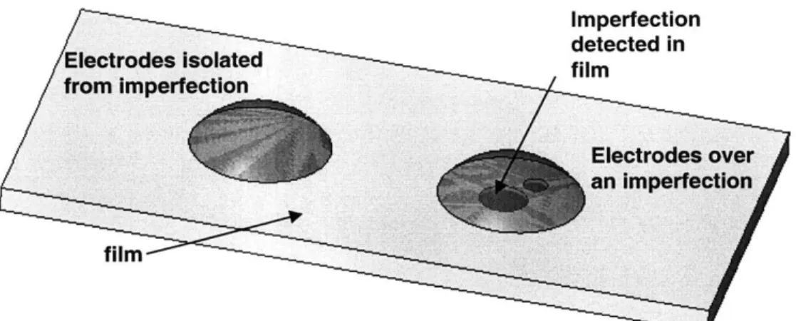
The presence of such imperfections in the VHB material has not been characterized previously. In order to characterize these imperfections, the material was pre-strained to its working conditions and then examined for such impurities. Visual inspection with the naked eye alone reveals many potential defects. These features are not visually apparent before pre-strain, but as the film is stretched, they "appear." One such feature is shown, magnified 100x, in Figure 10(a). Figure 10(b) shows a view magnified 400x. The exact nature of the imperfection is not obvious, but in the magnified view a
small bubble is obvious. It is suspected that the non-distinct, darkened regions are small pitted regions. The occurrence of these is totally random. For several samples, they
2
(a) (b) Figure 10: A single imperfection in a piece of VHB film, magnified at 100 and 400x.
The nature of these imperfections is not completely known. Typically, when a dielectric is manufactured, extreme care is taken to prevent the formation of voids. For example, a rigorous vacuum treatment is used to remove gaseous pockets from within the polymer in its liquid state. However, since VHB is actually manufactured for commercial use as a double-sided adhesive tape, the presence of gaseous pockets or foreign particles does not have a significant effect on its performance, and it is not necessary to eliminate them. A description of the exact process used to develop this material is protected information, and therefore the precise nature and cause of the foreign particles in not known.
In order to experimentally determine what effects, if any, these have on the strength of the film, the dielectric strength of a region containing such an imperfection was compared to that of an area not containing such an imperfection. This was done by applying a very small amount of compliant electrodes onto the film and then ramping up the voltage on these electrodes until failure. An illustration of the experiment is shown in Figure 11.
Figure 11: Breakdown testing for two different cases, both over and isolated from visually detected imperfections.
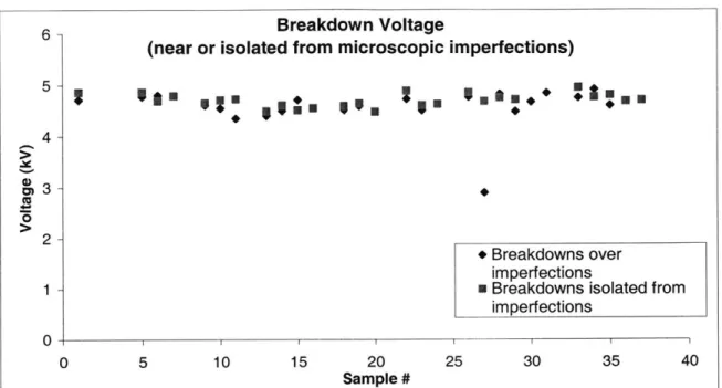
A sample of the raw data is shown in Figure 12. It can be seen that there is a
significant decrease in average dielectric strength when large visual imperfections are observed. The scatter in the data is most likely due to the fact that each imperfection is unique, so it will have different stress (electric or mechanical) enhancing effects on the materials
6- Breakdown Voltage
(near or isolated from visual imperfections)
5-.... "..
*
.:...
B... .u+ .* . "'m.p. ** > . 4-.X. 43-+2 - Breakdowns over imperfections
M Breakdowns isolated from imperfections
0 5 10 15 20 25 30 35 40
Sample #
Figure 12: Failure voltage from electrodes both adjacent to and far from visual imperfections.
There is clearly a negative effect due to the visual imperfections. Though a few samples breakdown at the expected level (approximately 4.6 kV), most of them fail at significantly lower values. The average breakdown value for the two sets is 3.91 kV and
4.58 kV, a difference of about 17%. Also, the standard deviation for the "over imperfection" case is 0.75 kV, and only 0.10 kV for the "clean" case. This indicates that nature or size of the imperfections is irregular and their effects are inconsistent.
Other samples were then examined for the presence of smaller, or microscopic, imperfections or voids. A magnification of 400X was used to scan the film for such imperfections. Several candidate imperfections were found, such as the one shown in Figure 13. Identification of such imperfections is very difficult. These were determined to be inclusions within the material because they could only be brought into focus in planes between the surfaces of the film and because each occurrence appears to have a vertical aspect ratio, the same direction of the pre-strain. If there is a small inclusion or cluster of inclusions, pre-stretching the film primarily in one direction would cause an elongation of the cluster in that direction.
Figure 13: Microscopic inclusions or void.
The process of determining the potential effects of these clusters was investigated in the same way as the larger imperfections. The raw data from these experiments is shown in Figure 14.
I
I0*
a
N
':
,'MBreakdown Voltage
(near or isolated from microscopic imperfections)
5- 4- ~)3-0 21 -0 30 35 40 5 10 15 20 Sample # 25 * Breakdowns over imperfections
* Breakdowns isolated from imperfections
Figure 14: Failurevoltage from electrodes both adjacent to and far from microscopic imperfections.
The majority of the points for both testing conditions have very similar breakdown values. However, one point (1 out of 25) lies significantly below the trend and indicates a pre-mature failure. There are two possibilities to explain the single point that lies well outside the trend:
- It had nothing to do with the imperfection (possibly due to undetected human error during testing), and can be discarded.
- It was caused by the imperfection, and this imperfection had a much more significant effect on the dielectric strength than the other microscopic imperfections.
With the data available, it is impossible to determine the cause, and with the number of points available, the "outlier" cannot be discarded. To determine its effect, a statistical analysis of the data sets, considering both possibilities, is shown in Table 2.
6
0
M
Table 2: Statistical analysis offailure data (breakdown voltage)
Average (kV) Standard Deviation
Visual imperfections Directly over 3.91 0.75
(macroscopic) Isolated from 4.58
0.096
Microscopic Directly over 4.48 0.395
imperections Isolated from 4.61
0.124
Microscopic Directly over 4.55 0.151
imperfections (bad
point discarded) Isolated from 4.61 0.124
By dropping the point, the difference between the averages is negligible (1%). Even with
the point, the difference is only 3%.
If the imperfection that was detected did cause the failure, this data indicates that it
was a different type of imperfection (for example, it may have been a conducing particle) than the other microscopic imperfections, which in general do not cause pre-mature failure. Most detectable imperfections are "harmless" (over 95% of those found). For future tests, more powerful examination tools should be used so that the specific nature of each imperfection can be determined. General guidelines for avoiding only hazardous imperfections, such as the one found in this experiment, cannot be put into effect if these cannot be separated from harmless defects. It may also be possible, once the nature of this single point is characterized, to use detection methods other than visual inspection. For example, if only metallic microscopic imperfections are hazardous, then these could simply be found and eliminated using a metal detector. For future investigation of microscopic imperfections, it is necessary that more dependable and efficient detection methods be developed so that larger and more reliable data sets can be achieved.
Though this experiment does not reveal any significant negative effects for most microscopic inclusions or voids, such effects cannot be ruled out. In section 2.4.4, an investigation of stress concentrations at the edges of electrodes will show that failures are most likely to occur at electrode edges, and therefore the effects of most microscopic imperfections might be negligible in comparison (while large defects definitely cause pre-mature failures) to the breakdown mechanism at the edge of the electrode. However, it stands to reason that if stress concentrations at the edge of the electrodes were to be eliminated by future design or fabrication methods, then small film defects might become
a more significant factor. Furthermore, the mechanism of failure by internal discharging is a time dependent effect [45]. The pitting and heating within these voids might not cause failure within the time domain of these tests, but for large actuation times or cycles, the material strength at these locations will decrease, so that in time failure might occur.
The presence of gaseous voids within the film can also lead to non-negligible current flow through the material. In the ideal case, with a perfect dielectric between the electrodes, there would be zero current flow. However, no polymer is a perfect dielectric, and there is charge leakage through the film. A constant (though low) supply current is necessary to maintain a constant voltage across the film. In the normal case, with high quality film (two films laminated together with no visual air bubbles) approximately 200 microns thick and with an area of 10 cm2, and a potential difference of approximately 3
kV, the current through the actuator is on the order of 1 pA. Another film with the same area and thickness was also laminated. However, during the assembly process, several air bubbles were purposely trapped between the two films. These bubbles covered about 10% of the actuator area. In this case, the current was on the order of 100 pA, approximately 100x greater than for the standard case. Premature failure was not induced because the electric field was maintained at a voltage significantly less than the breakdown value.
The effect of increased current leakage is significant from an efficiency point of view. The power dissipated by an element is equal to the product of the potential difference across and the current through the element. An increase of the current by a factor of k will effectively decrease the efficiency by a factor of k.
The major conclusion that can be obtained from these simple experiments is a qualitative design rule. The film should not contain any visible voids or defects that can be detected by the naked eye, as they significantly decrease the strength of the material. While most microscopic imperfections appear to have no effect on material strength, some may have detrimental effects. If the process for detecting and identifying these is very difficult and time consuming relative to the effort required to build the actuator (as is the case for current methods), and very few microscopic imperfections are likely to cause
premature failure (less than 5%), then it would be more efficient to fabricate the entire actuator and then test it, and then discard the entire actuator if it fails at that time.
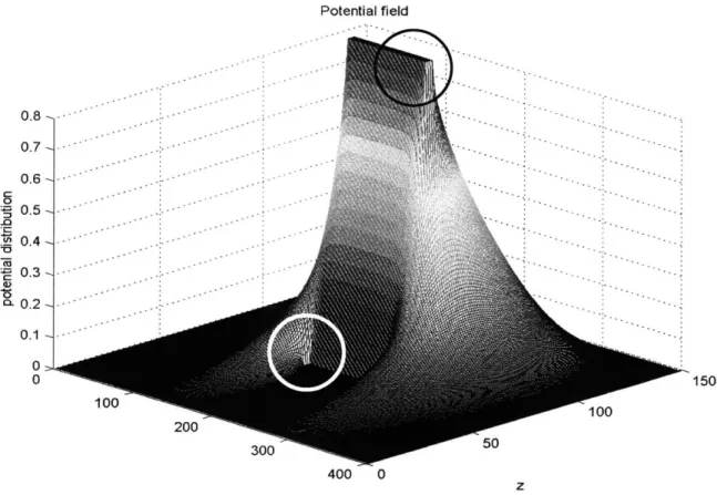
2.4.4 Electric Field Concentrations
Experimental data also revealed that dielectric failure consistently occurs at the edges of electrodes. Initially, these types of failures were observed at the edges of the electrode where it meets a supporting frame. Preliminary hypotheses identified the cause of these failures as either mechanical stress concentrations or electric field concentrations. Mechanical stress concentrations could be due to the change in boundary conditions where the film is constrained to frame.
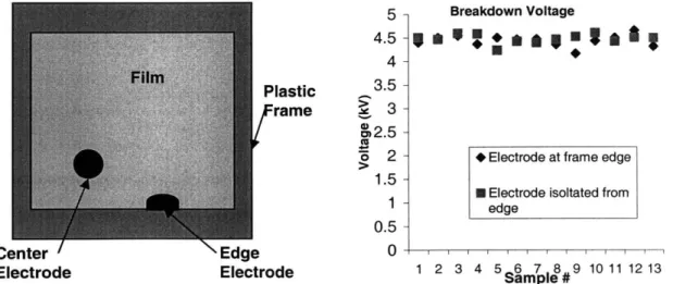
Experiments were performed to determine if film was more likely to fail because it was adjacent to a constrained edge. First, electrodes were applied to the center of the film, away from external frames, and the potential difference between the electrodes was increased until failure. Visual inspection showed that failures still occurred on the perimeter of the electrode. A second experiment showed that maximum voltage levels do not change based on the proximity to constrained edges, as illustrated by the data in Figure 15. Breakdown voltages were measured for electrodes placed both next to and
away from rigid frames. The difference in the averages for the two data sets was about 2%, showing no clear difference between maximum sustainable voltage between the two cases. 5 - Breakdown Voltage 4.5
5
1
*0*
4- 3.5-Plastic 3.-rame 3-C 2.5-o 2 - Electrode at frame edge
1.5
N Electrode isoltated from
1 edge
0.5-Center Edge 0
Electrode Electrode 1 2 3 4 5 6 7 8 9 10 111213
Sample #