HAL Id: hal-00301683
https://hal.archives-ouvertes.fr/hal-00301683
Submitted on 15 Jun 2007
HAL is a multi-disciplinary open access
archive for the deposit and dissemination of
sci-entific research documents, whether they are
pub-lished or not. The documents may come from
teaching and research institutions in France or
abroad, or from public or private research centers.
L’archive ouverte pluridisciplinaire HAL, est
destinée au dépôt et à la diffusion de documents
scientifiques de niveau recherche, publiés ou non,
émanant des établissements d’enseignement et de
recherche français ou étrangers, des laboratoires
publics ou privés.
Slope stability assessment of weathered clay by using
field data and computer modelling: a case study from
Budapest
P. Görög, A. Török
To cite this version:
P. Görög, A. Török. Slope stability assessment of weathered clay by using field data and computer
modelling: a case study from Budapest. Natural Hazards and Earth System Science, Copernicus
Publications on behalf of the European Geosciences Union, 2007, 7 (3), pp.417-422. �hal-00301683�
www.nat-hazards-earth-syst-sci.net/7/417/2007/ © Author(s) 2007. This work is licensed under a Creative Commons License.
and Earth
System Sciences
Slope stability assessment of weathered clay by using field data and
computer modelling: a case study from Budapest
P. G¨or¨og and ´A. T¨or¨ok
Budapest University of Technology and Economics, Department of Construction Materials and Engineering Geology, Stoczek u. 2., H-1111 Budapest, Hungary
Received: 11 October 2005 – Revised: 19 December 2006 – Accepted: 1 June 2007 – Published: 15 June 2007
Abstract. A future development site of a housing estate, an
abandoned-brick yard with clayey slopes was studied in de-tails to assess slope stability and to calculate the factor of safety. The Oligocene clay, the former raw material, is di-vided into two different geotechnical units in the clay pit. The lower one consists of grey impermeable clays while the upper unit is characterised by yellowish weathered clay hav-ing a limited permeability. At some localities the topmost weathered clay layers are covered by loess, and slope de-bris. Parts of the former pit were also used as a landfill site. The slope stability analyses were performed based on bore-hole information and laboratory analyses in order to provide necessary engineering geological data for further site devel-opment and urban planning. Two geotechnical codes Plaxis and Geo4 were used to model the slope failures and assess the slope stability. The aim of using two different approaches was to compare them since Plaxis uses finite elements mod-elling while Geo4 uses conventional calculation methods to obtain circular and polygonal slip surfaces. According to model calculations and field data, the main trigger mecha-nisms of landslides seem to be high pore pressure due to rain-water and small slope debris covered springs. The slip sur-face is located at the boundary zone of yellow weathered and grey unaltered clay. Two computer models gave very sim-ilar results; although Plaxis provides combined safety fac-tor which is slightly more pessimistic when compared to the safety factor obtained by using Geo4.
1 Introduction
Urban development often conquest areas of previous quar-ries and pits. These locations are used as landfill sites and subsequently face to slope stability problems. Additionally,
Correspondence to: ´A. T¨or¨ok (torokakos@mail.bme.hu)
the forced utilization of inherently unstable slopes and clay pits often cause landslides and thus slope stability analyses of such areas are essential for urban planning and site devel-opment.
To assess the present state of abandoned quarries or pits, field surveys of discontinuity surfaces, weathering maps and shear strength tests are used (Koca and Kinsal, 2004). Slope stability analyses of recent landslides and potential slide ar-eas include on site monitoring by using extensiometers and tensiometers (Okamoto et al., 2004), piezometers (Angeli et al., 1998) as well as collecting data on precipitation and lo-cal geology (Calcaterra and Santo 2004). The mineralogilo-cal and geotechnical parameters of clayey slopes are obtained by laboratory testing (Calcaterra and Santo, 2004) and conven-tional parameters such as LL (liquid limit), PL (plastic limit), PI (plasticity index) are used for slope stability assessments (Isik et al., 2004). In computer modelling of slopes finite element models are commonly used (Isik et al., 2004). Simi-larly to others cities, the urban development of Budapest fo-cuses on the development of scarce available lands that are located within the area of the city. Oligocene clay covers large areas in Budapest, Hungary. The subsoil of the most valuable lands of Buda is usually this clay. In the municipal area of Buda, there are three ancient clay pits, where several landslides occurred. These areas would be potential building sites of Budapest, but landslides developed in weathered clay hamper the site development. In this paper, the slope stability of an ancient brick-yard is presented by modelling the load of the future buildings and analysing the slope stability. Two geotechnical codes were used having different approaches to calculate the slope stability and safety factors. The results of finite element calculation method (Plaxis software) and cal-culation of circle and polygonal slip surfaces with conven-tional methods (Geo4 software) are presented and compared here.
418 P. G¨or¨og and ´A. T¨or¨ok: Stability assessment of weathered clay, modelling 180 170 160 150 140 130 120 190 200 180 180 220 230 240 250 260 270 280 290 300 310 320 330 340 350 270 360 370 380 390 400 410 420 430 440 450 460 0 100km N BUDAPEST HUNGAR Y 0 100200 300m Hár masha tár hill
Drasche claypit
N
Studied area
Fig. 1. Location map and site plan of the study area.
2 Mining activity and landslides
Oligocene clay formation of Budapest (Kiscell clay) has been used for brick and tile production from the middle of the 19th century. The need for proper raw material and rising produc-tion of construcproduc-tion materials led to the opening of large and steep clay pits. This unplanned and rapid development often caused landslides in the past, when the brick works were still in operation. By now, most of the clay pits are abandoned and have been partly or entirely filled with mine waste or mixed landfill. The study area is a typical example of such a clay pit, which was cut into a clayey slope. Prior to clay pro-duction, the natural slope also experienced landslides, thus records of fossil landslides are also known. The clay ex-ploitation, which began in the second half of the 19th cen-tury, accelerated the sliding, because steeper slopes were cut. The improper mining and the insufficient drainage induced several catastrophic landslides. The landslides endangered buildings and streets and there was a plan to close the mining activity in the 1920’s but due to the “post-war” reconstruc-tion works the clay exploitareconstruc-tion continued till 1972 (N´emeth, 1980). The cover beds of the raw material were stripped and deposited on the margins of the pit, especially on the south-ern part. This deposit consists of yellow weathered part of the clay formation and additionally it contains clayey slope debris with rock fragments and loess. After terminating the clay production the pit was used as a waste disposal site, and thus nowadays it is filled with heterogeneous landfill. The filling material is quite heterogeneous it contains household waste from Budapest and even excavated materials from the tunnelling works of the metro (N´emeth, 1980).
3 Geology, hydrogeology
The studied clay pit is located at the foot of a hill (H´armashat´ar-hegy) in Budapest (Fig. 1). The bedrock is a massive Triassic limestone/dolomite, which is covered by
Eocene limestone and marl. The raw material deposits of brick-yard are found on the east slopes of the hill. These Oligocene clay formations are subdivided into two lithos-tratigraphic units: the lower one is Tard clay, while the upper one is Kiscell clay. Largest parts of the brick-yards are cut into the upper and younger clay unit, into Kiscell clay. This clay formation is divided into grey and yellow clay units. The lower grey layers are impermeable, while the upper yellow clay show signs of weathering and has a limited permeabil-ity (Vendl, 1932; Pa´al, 1997). The grey clay contains pyrite, while in the yellow clay the pyrite is oxidized and limonite is the main iron mineral. The clays are covered by Pleistocene loess. Subsequently the loess was mixed with the weathered yellow and unaltered grey Oligocene clay (Kiscell clay) due to erosion and landsliding, resulting in the formation of a slope debris layer. The thickness of the slope debris layer is 1 to 10–15 m. The main water-catchment area is the hillside above the pit. Meteoric water seeps through the slope debris and the weathered yellow clay and reaches the surface of the grey clay. Additional water seepage was documented from cracked drainage pipes that were designed to collect runoff waters. Spring water also reaches the slide surface since an-tecedent small springs were covered by slope debris of for-mer landslides (Pa´al, 1998). For comparing the two different computer models and for calculations of safety factor an area located on the SE edge of the clay pit was selected (Fig. 1). On this slope the damp material was deposited in the 1950’s.
4 Field survey and drillings, laboratory analyses
In order to analyse the ground conditions and detect possi-ble slip surfaces, 19 boreholes were drilled at the study area. When drillings did not provide sufficient data, shallow seis-mic reflection profiles were made to delineate the slide sur-face. Based on the field survey it was possible to describe the subsurface geology of the study area. The topmost beds of the slope consist of clayey slope debris, which is considered as spoil of former mining activity. It has a thickness of few to 17 m. Besides clay, it contains smaller rock fragments and few brick fragments. It is underlain by yellow clay, which is considered as the uppermost weathered zone of the grey clay. The yellow clay does not uniformly cover the slope; there are zones, where this formation is missing due to fault activity (Fig. 2). At the toe of the slope black waste and slug landfill were found below the slope debris. In the upper slope zones, no groundwater was found in 1998 (May and June) while at the lower slopes perched groundwater was located a few me-tres below the surface in the black waste and slug landfill. Grey impermeable clay forms the lowermost exposed beds. The previous studies (Pa´al, 1998) have demonstrated that the grey clay forms an extensive basin fill at the study area. A narrow fault zone is suggested to occur near C4 borehole, but it caused minor displacement thus it was discarded during the model calculations. The clayey slope debris layer is more
Table 1. The physical-mechanical parameters used for the model.
soil type ρn[kN/m3] φ[◦] c[kN/m2]
yellow clay and clayey
slope debris 19 15 50
landfill containing
waste and slag 14 5 1
grey clay 22 30 250
than 50 years-old and thus it has been consolidated and has moderate load bearing capacity (Pa´al, 1998). The borehole data suggests that weak clayey zones are found within the slope debris at some places. Grey clay has a good load bear-ing capacity accordbear-ing to Vendl (1932) and Pa´al (1997). For the slope stability analyses, the geotechnical and physical pa-rameters of slope debris and yellow and grey clay were tested under laboratory conditions. LL (liquid limit), PL (plastic limit), PI (plasticity index), shear strength and water con-tent were analysed. For the computer modelling of slopes, the weakest recorded parameters were used (Table 1). The landfill consists of fine graded slag, organic waste and it is very heterogeneous and compressible with very weak soil-physical parameters. The yellow clay has a higher cohesion and is very similar to slope debris therefore these two beds are considered as only one layer. The grey clay has the
high-est ρn, φ and c values (Table 1).
5 Model conditions
The slope stability and factor of safety were analysed in se-lected sections along the slope by using Plaxis and Geo4 soft-ware. These two codes were used to model since these have different approaches to calculate slope stability. The Plaxis is one of the most widespread code works with finite elements method and capable to model complex slope morphology. It calculates the weakest point of the slope but it does not al-ways draw a geologically feasible slip surface. Geo4 soft-ware uses conventional methods, and calculates circular slip surface by using Bishop’s method (Bishop, 1955) or polyg-onal slip surface applying Sarma’s method (Sarma, 1973). The slip surface can be manually entered to Geo4. It is pos-sible to compare the circular slip surface and a similar slip surface which is calculated from vertical polygons by using this code. For the upper slope section the polygonal verti-cal slices (Sarma, 1973), while for the lower slope circular slip surface model was the one which provided the best re-sults since according to borehole data the slip surface does not penetrated into the lower grey clay. The computer mod-els were applied to draw the slip surfaces and calculate fac-tors of safety along a section, which is shown in Fig. 2. A three-layer soil model was applied to describe slope stability features. The lowermost layer is the impermeable grey clay;
grey clay grey clay yellow weathered clay yellow weathered clay
black waste and slug landfill black waste and
slug landfill weathered clayey slope debris (16.0) Gw.: ---(16.0) Gw.: ---(23.5) Gw.: ---(23.5) Gw.: ---(1.3) Gw.: ---(1.3) Gw.: ---(19.0) (16.5) (7.5) Gw.: ---(7.5) Gw.: ---6.1 14.3 16.7 5.8 17.4 2.7 11.8 14.9 3.9 6.9 C1 174.27C1 174.27 C2 163.51 C2 163.51 C4 157.06C4 157.06 C3 136.86C3 136.86 B1 125.62B1 125.62 B2 124.14 B2 124.14 8 122.10 8 122.10 5.3 14.6 (16.5) Gw.: ---(16.5) Gw.: ---180.0 170.0 160.0 150.0 140.0 130.0 120.0 110.0 100.0 150 m 150 m 100 50 0 Asl.
Fig. 2. The geological profile of the slope used in model calculation
showing the location of drillings (borehole data from Pa´al, 1998).
the upper layer includes both, the yellow weathered clay and clayey slope debris having very similar physical properties. The third layer, the waste landfill was only inserted in the lower slope and toe of slope part, where it is located below the slope debris. This model is in accordance with the bore-hole data and our field observation, that landfill is only found in a depression at the lower part of the slope (Fig. 2). The in-put parameters of the model were obtained from laboratory tests. The weakest measured values were used (Table 1) to have a realistic model, and to calculate the factor of safety. The stability of the clayey slope and the toe area in front of the slope were also analysed. Another aim of our analyses was to demonstrate the effect of the site development on the
slope stability by using a 300 kN/m2distributed load at the
top of the slope. These model conditions represent the situa-tion when houses are built upslope.
6 Stability analyses and results
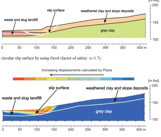
Stability of the natural slope was analysed in the first set of models. Geo4 software needs an initial slip surface as an in-put and the software optimise it. Namely, it searches the loca-tion of the slip surface when the safety factor is the smallest. It can both work with circle and polygonal slip surfaces. The slope can be divided into two parts since the upper part is best modelled with a two-layer model while at the lower part waste and slag landfill occurs, and thus a three-layer model was applied. At first, the weakest point of the slope was de-termined, where the factor of safety has a minimum value. It was found to be at the foot of the slope deposit. The circular slip surface penetrates into the waste and slag landfill when Geo4 software calculations were applied (Fig. 3). In this case the calculated factor of safety is n=1.7. For comparison, the same geological structure was used for finite element model calculations. The analyses with the Plaxis almost gave the same slip surface (Fig. 4) and the calculated factor of safety
420 P. G¨or¨og and ´A. T¨or¨ok: Stability assessment of weathered clay, modelling
waste and slug landfill waste and slug landfill
grey clay grey clay
weathered clay and slope deposits weathered clay and slope deposits slip surface slip surface 0 50 100 150 200 250 300 350 400 m 100 150 200 [m Asl]
Fig. 3. The calculated circular slip surface by using Geo4 (factor of safety: n=1.7).
waste and slug landfill waste and slug landfill
grey clay grey clay
weathered clay and slope deposits weathered clay and slope deposits slip surface slip surface 0 50 100 150 200 250 300 350 400 m 100 150 200 [m Asl] Increasing displacements calculated by Plaxis
Fig. 4. Displacement distribution of the slope with surface load calculated by Plaxis (factor of safety: n=1.6).
is slightly less (n=1.6). Nevertheless, it is necessary to note that the Plaxis works with combined factor of safety. Con-sequently a factor of safety n=1.6 calculated with Plaxis is equal to a factor of safety of n=1.7–1.8 calculated with con-ventional method.
The supposed sliding mass was divided into n vertical slices according to Sarma (1973). It gave a polygonal slip surface which was also modelled by Geo4. A factor of global safety was also calculated with Geo4, since the global factor of safety of the slope cannot be analysed with Plaxis. It is related to the fact that in the finite elements modelling such as Plaxis the location of the slip surface can not be manually adjusted. The lower part of polygonal slip surface coincides with the circular slip surface while the upper part of it fol-lows the boundary zone between the impermeable grey clay and the overlying weathered clay and slope debris (Fig. 5). The factor of safety with this polygonal slip surface is n=2.0. The angle of friction of the weathered clay and slope de-bris is higher than the angle of the slope, thus the global fac-tor of safety is higher compared to the case when the circular slip surface was modelled. For the lower part of the slope where waste and slag landfill are also present, the safety fac-tor is smaller thus these layers cannot support the slope es-pecially when water infiltrates. The main trigger mechanism of landslides is related to rainwater infiltration. The precipi-tation water infiltrates into the weathered clayey slope debris
and seeps via the yellow weathered clay down to the bound-ary to grey clay. In this boundbound-ary zone, where the slip sur-face is located, the water significantly reduces the physical parameters of both clays, by increasing pore water pressure and decreasing friction angle and cohesion. Former expe-riences have also shown that in similar clays (Okamoto et al., 2004), such as the yellow weathered clay, the increasing water-content radically decreases the angle of friction con-tributing to slope failures. According to model calculations the loads from house constructions on the upper slope have no significant influence on the safety factor when circular slip surface model is used. To the contrary it reduces the global safety of the slope to n=1.6, when the polygonal slip surface model is applied (Fig. 6).
7 Discussion
Geotechnical codes are used to analyse slope stability. Most of these codes are designed to calculate the weakest points of the slope and draw a slip surface. The behaviour of slopes is strongly controlled by the geological built up and water content especially when rock types very different from a me-chanical point of view are present such as conglomerates and marls (Eberhardt et al., 2005) and limestones covered with pyroclastic deposits (Calcaterra and Santo, 2004). In the case of heterogeneous geological built up the slip surface
waste and slug landfill waste and slug landfill
grey clay grey clay
weathered clay and slope deposits weathered clay and slope deposits slip surface slip surface 0 50 100 150 200 250 300 350 400 m 100 150 200 [m Asl]
Fig. 5. The calculated polygonal slip surface by using Geo4 (factor of safety: n=2.0).
waste and slug landfill waste and slug landfill
grey clay grey clay weathered clay and slope deposits weathered clay and slope deposits slip surface slip surface 0 50 100 150 200 250 300 350 400 m 100 150 200 [m Asl] load: 300 kN/m2 load: 300 kN/m2
Fig. 6. The calculated polygonal slip surface for building load by using Geo4 (factor of safety: n=1.6).
can not be modelled with a single circular slip surface but a more complex slip zone. Previous studies have shown that back analyses and numerical codes of unstable slopes pro-vide valuable data on slope failure analyses (Baron et al., 2005). In most cases infiltration of precipitation into the slide surface triggers landslide (Eberhardt et al., 2005) or human impact such as building load (Isik et al., 2004) can induce landslides even in stiff clays. The studied grey and yellow clay when wet show a decrease in physical parameters. The weathering and additional water infiltration can further re-duce the physical parameters as it has been shown for Alpine marls (Eberhardt et al., 2005). In numerical modelling the weakest parameters are used as input data for calculating the factor of safety, but the weakest points are calculated by the software. In this case field analyses and core-drilling data have shown that the slip surface drawn by the computer codes does not necessarily coincides with the boundary zone of weathered yellow clay and grey clay. Geological evidences and past landslides of similar areas (Pa´al, 1997) have doc-umented that the sliding surface is located at the boundary zone between yellow and grey clay. When computer codes are applied the slip surface is placed at a zone where there is a significant difference in between physical parameters of two layers. When the layers themselves are not very differ-ent but the weakest zone – the potdiffer-ential slip surface – is a very thin surface it is necessary to manually input an inter-face element in Plaxis to obtain the best results. In Geo4 it is necessary to create a new thin layer with reduced physical
parameters to model the slope failure. Consequently, field observations and geological data are needed to clarify model conditions and thus borehole data is essential to build a reli-able model in areas where slope consists of multiple layers of clays characterised by different physical parameters.
8 Conclusions
Two geotechnical software having different model ap-proaches were compared. The results for circular slip sur-face models when Plaxis (FEM calculations) and Geo4 (con-ventional Bishop’s method calculations) were used are very similar, the factors of safety were 1.6 and 1.7, respectively. Minor differences are related to the different approaches of the two software calculations. For polygonal slip surfaces Geo4 is the only software, which can be applied since the slip surface can be manually adjusted, while by using Plaxis it is not possible. The global factor of safety for polygonal slip surface was 2.0, due to the fact that slip surface were longer and it also reached the upper slope where larger fric-tion was documented. The weakest point of the slope was found within the waste and slag landfill, which is overlain by weathered clayey slope debris. Landslides are often trig-gered by high pore pressure usually due to infiltrating mete-oric water and clayey–slope-debris covered springs. The slip surface for circular model is located within the landfill while for polygonal model it is longer and located at the boundary
422 P. G¨or¨og and ´A. T¨or¨ok: Stability assessment of weathered clay, modelling zone of weathered yellow clay and impermeable grey clay.
The perched groundwater, the stagnant water of small springs and the seepage waters due to missing drain pipes can also in-crease the water-content of the subsoil and dein-crease the fric-tion. For understanding the mechanisms of slope failures it is suggested to use both models since for circular slip sur-face Plaxis, while for polygonal one Geo4 provided the best model for landslides. The application of laterally heteroge-neous model within one slope, two and three layer models in this case, provide valuable information on slope stability and failure scenarios.
Acknowledgements. We are very grateful to T. Pa´al who provided
field data and had several useful comments and suggestions. The help of B. Kleb is also acknowledged.
Edited by: D. Calcaterra
Reviewed by: I. Baron, D. Calcaterra and another referee
References
Angeli, M. G., Buma, J., Gasparetto, P., and Pasuto, A.: A com-bined hillslope hydrology/stability model for low gradient clay slopes in the Italian Dolomites, Eng. Geol., 49, 1–13, 1998. Baron, I., Agliardi, F., Ambrosi, C., and Crosta, G. B.: Numerical
analysis of deep-seated mass movements in the Magura Nappe; Flysch Belt of the Western Carpathians (Czech Republic), Nat. Hazards and Earth Syst. Sci., 5, 367–374, 2005.
Bishop, A. W.: The use of the slip circle in the stability analysis of slopes, G´eotechnique 5, 1, 7–17, 1955.
Calcaterra, D. and Santo, A.: The 10 January 1997 Pozzano land-slide, Sorrento Peninsula, Italy, Eng. Geol., 75, 181–200, 2004. Eberhardt, E., Thuro, K., and Luginbuehl, M.: Slope instability
mechanism in dipping interbedded conglomerates and weathered marls – the Rufi landslide, Switzerland, Eng. Geol., 77, 35–56, 2005.
Isik, N. S., Doyuran, V., and Ulusay, R.: Assesment of a coastal landslide subjected to building loads at Sinop, Black Sea region, Turkey, and stabilization measures, Eng. Geol., 75, 69–88, 2004. Koca, M. Y. and Kincal, C.: Abandoned stone quarries in and around the Izmir city centre and their geo-environmental impacts – Turkey, Eng. Geol., 75, 49–67, 2004.
N´emeth, G.: Analyses of the sliding at the ´Ujlak 3rd pit, near the Jablonka street [in Hungarian], M´ely´ep´ıt´estudom´anyi szemle, 30, 195–206, 1980.
Okamoto, T., Larsen, J. O., Matsuura, S., Asano, S., Takeuchi, Y., and Grande, L.: Displacement properties of landslide masses at the initiation of failure in quick clay deposits and the effects of meterological and hydrological factors, Eng. Geol., 72, 233–251, 2004.
Pa´al, T.: Geotechnical analysis of the area of ´Ujlak clay pit no. II. [in Hungarian], M´ely´ep´ıt´estudom´anyi szemle 47, 7, 295–303, 1997.
Pa´al, T.: Geotchnical report on the soil mechanical investigations of the Drasche brick-yard (in Hungarian), 32p, 1998.
Sarma, S. K.: Stability analysis of embankments and slopes, G´eotechnique 23, 423–433, 1973.
Vendl, A.: Kiscell clay [in Hungarian], F¨oldtani Int´ezet ´Evk¨onyve XXIX, 2, 97–156, 1932.