Multi 3D-PTV system for airflow study in large
enclosures
Masoumeh Nedaei
1, Pascal Biwole
1, Gilles Jacquemod
2, Fabienne Pennec
1, Eric
Dekneuvel
2& Florence Labesse-Jied
1.
1 Université Clermont Auvergne, CNRS, SIGMA Clermont, Institut Pascal, F-63000 Clermont–Ferrand, France
2Université Nice Sophia Antipolis, Department of Sustainable and Smart Buildings, Polytech’Lab EA, 7498, Sophia Antipolis, France
RÉSUMÉ.Les données obtenues par vélocimétrie par suivi de particules (3DPTV) sont essentielles pour l’étude des flux d’air intérieurs dans les bâtiments afin d’optimiser les stratégies de HVAC et de surveiller les polluants en suspension dans l’air. Le 3DPTV fournit une mesure quantitative de la vitesse d'écoulement et de la trajectoire par suivi 3D de particules discrètes à flottabilité neutre plongées dans un fluide. Cependant, les volumes de mesure 3D-PTV doivent être étendus pour pouvoir être appliqués à des scénarios réels. Pour ce faire, nous proposons une méthode d'utilisation de plusieurs systèmes 3DPTV composés chacun d'au moins trois caméras synchrones. L'une des exigences de cette approche est qu'au moins une caméra ait une vue sur la cible d'étalonnage du système suivant. L'étalonnage des caméras est effectué séparément pour chaque système, de manière à obtenir la relation mathématique entre le repère pixels 2D de chaque caméra et repère 3D commun. Des particules synthétiques sont également créées, de façon à tester les algorithmes développés dans Matlab pour des écoulement de Kovasznay et de Beltrami pour lesquels les solutions des équations de Navier-Stokes sont connues.
MOTS-CLÉS: circulation d’air à l’intérieur, vélocimétrie par suivi de particules en 3D, grande échelle, solution
Navier-Stokes, vision par ordinateur
ABSTRACT. High-quality data obtained from large scale 3D particle tracking velocimetry (PTV) are pivotal for indoor
airflow study in buildings and more specifically, in large areas such as conference halls, to optimize HVAC strategies and monitoring airborne pollutants. 3D-PTV provides quantitative measurement of flow velocity and trajectory by 3D tracking of neutrally buoyant discrete particles immersed in a fluid. However, 3D-PTV measuring volumes need to be extended to be applicable in real-world scenarios. To achieve this, we propose a method of using multiple 3D-PTV systems each composed of three time-synchronous cameras to capture a broad view of the fluid. One requirement for this approach is that at least one camera should have a view over the calibration target of the next system. Calibration of the cameras should be performed separately for each system so that the mathematical relationship between their individual 2D pixel reference frame and a common 3D reference frame is obtained. Synthetic particles will be also created that follow algorithms developed in Matlab for laminar macroscale flows of known Navier-Stokes solutions, so-called Kovasznay and Beltrami.
settings; however, there are many challenges yet to be overcome. The limited measuring volume of the 3D-PTV system is one important challenge, which needs to be extended to cover all the measuring volume. In buildings and in large areas such as conference or theater halls, and office rooms, large-scale 3D-PTV could play a significant role in order to predict the trajectory and velocity of the air and airborne pollutants. This will be beneficial from both environmental and energetic aspects. Regarding the environmental aspect, indoor air may contain particles spread by human action or equipment. These particles may be dangerous chemicals such as carbon monoxide or formaldehyde, which can be even mortal. The aim is to be able to predict the trajectory of airborne particles to optimize ventilation strategies and to take necessary precautions or actions during hazardous events such as moving out people. Concerning energy, 3D-PTV can help in optimizing heating or cooling systems to achieve indoor thermal comfort. This can be obtained by adapting a suitable shape and location of the air conditioning systems in order to cover a larger area and accordingly, to achieve the best thermal comfort at a lower cost. Airflow can be simulated using Computational Fluid Dynamics (CFD) modeling to predict airflow fields (temperature, velocity, and pressure) and airflow patterns (trajectory, vortices, etc…). Most studies in the literature concerning building sciences apply CFD methods; however, there is still a lack of a complete understanding of the local airflow fields surrounding thermal devices. Consequently, performing numerical studies accompanied by experimental measurements still plays a significant role in understanding indoor airflow structures.
There are generally two types of methods for measuring airflow: point-wise and global-wise. Local probes such as hot wires/spheres/film anemometry [POP 98] or laser Doppler velocimetry and ultrasonic anemometry [WAS 99] are all accounted as point-wise technologies. These technologies are mostly intrusive meaning that they may disturb the local airflow. In the global-wise technology, particle tracers and visualization methods are used in technologies such as Particle Image Velocimetry (PIV), Particle Streak Velocimetry (PSV), and Particle Tracking Velocimetry (PTV). This method can effectively resolve the disadvantages of the point-wise technology and therefore, has been widely used in airflow studies, especially the PIV technology. However, typical PIV technology that uses laser techniques usually cannot be used outside the laboratories due to security reasons. Moreover, the measurement volume is still limited to a few cubic centimeters [CAO 14]. The PSV technology has an excellent performance in the case of 2D flow fields, but shows a poor performance in 3D fields. The reason is attributed to the use of a narrow laser sheet to avoid the streaks to be truncated [ADR 91]. PTV technology utilizes both fewer particle tracers and usual illumination devices in comparison with the PIV and therefore is more beneficial for a complete characterization of airflow on a large scale. Kim et al. [KIM 12] conducted experiments on a confined-shear-driven liquid droplet over a moving surface to compare micro-scale measurements of tomographic PIV and 3D-PTV. Biwole et al. [BIW 09] proposed a complete 3D-PTV algorithm for indoor airflow study and investigated their applications in four different experimental conditions e.g. inside an experimental aircraft cabin. However, such studies are still lacking in large-scale measuring volumes.
Motivated by the above-mentioned studies, the aim of our work is to overcome the current limitation of the measuring volume of the 3D-PTV. This limitation prevents employing 3D-PTV for characterization of the airflow in large enclosures such as auditoriums, with a suitable spatial resolution. This study introduces a method for combining multiple 3D-PTV systems, installed side by side, in order to measure airflow and pollutants in large areas. A common multi calibration procedure is also presented. An algorithm is developed for linking trajectories of the particles passing through the view of the cameras. Two different particle motion algorithms for Navier-Stokes solutions, namely Kovasznay and Beltrami flows, are also developed in Matlab to evaluate the performance of the multiple 3D-PTV systems.
2. Experimental Setup
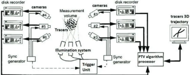
In this study, two 3D-PTV systems are being considered for the sake of simplicity. However, the same procedure can be applied for an extended number of 3D-PTV systems. Each system is composed of at least 3 cameras to achieve three-dimensional flow characteristics. The cameras should be time synchronous so that each image should be taken at the same time by all the cameras. Figure 1 displays a schematic of the multi 3D-PTV considered in this study. All the cameras in each system should be separately calibrated to calculate a mathematical relationship between their 2D pixel coordinates and the common 3D reference frame as explained in section 2.1. Section 2.2 details an algorithm to create a link among the particle trajectories.
2.1 Multi-Camera Calibration
The objective of the calibration is to find a relationship between the 2D pixel coordinate of each camera and the 3D real-world coordinate system. Then, the output of this procedure is the coefficients taking part in the mathematical relationship between the two systems: (i) intrinsic parameters defining the internal camera hardware that should be calculated separately for each camera by giving several positions of a calibration target to the algorithm. The intrinsic parameters include focal length, skew angle, principal point, and distortion coefficients; (ii) extrinsic parameters, which depend on the camera position, including rotation and translation matrices and obtained at a specific position of the calibration target. The pinhole camera model is considered in this study which is similar to the one suggested by Heikkila and Silven [HEI 97]. The calibration method used is performed with a 2D planar checkerboard and it does not necessarily require a full 3D calibration target. Generally, calibration parameters are determined by minimizing the distance between the specific locations on the calibration object and the same locations calculated by the mathematical model of each camera [BEA 92]. The calibration method used in this work is the one proposed by Zhang [ZHA 99] and implemented in Matlab by Bouguet [BOU 04] in a Camera Calibration Toolbox. Firstly, the calibration of each system should be performed independently. One indispensable requirement is that at least one camera in one system should have a view over the calibration target of the other system to be able to define a common reference frame for all the particle trajectories.
Here, we noted the two systems as “m” and “n”. Equation (1) transforms camera ith coordinates system XXC into the calibration target coordinate system XX in system n; where Tinand Rin represent respectively 3×1 translational vector and 3×3 rotational vector of camera i in system n:
[ 1 ] If camera i of system n also sees the calibration target of system m which defines the common 3D reference frame of that system, then the relationship between XXCinand XXm can be written as:
[ 2 ] From equation (1) and (2), the relationship between XXm and XXn can be deduced as:
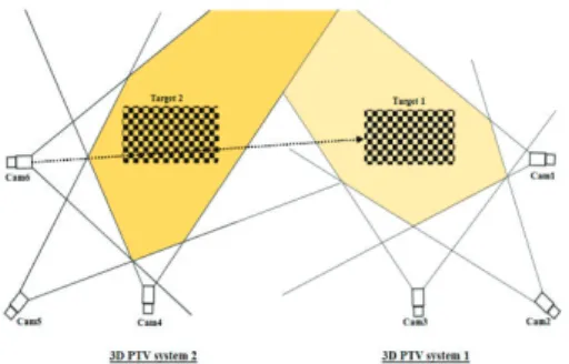
[ 3 ] Considering Fig. 2, where camera 6 of system 2 sees the calibration object of system 1, equation (3) can be rewritten:
[ 4 ] Therefore, all the particle trajectories are expressed in the same common reference frame.
Figure 3.Particles passing from one system to another
2.2 Linking trajectories
This section introduces a method to establish a link among the particle trajectories separately calculated for each 3D-PTV system. It is assumed that there is a non-zero intersection in the 3D fields observed by the two adjacent 3D-PTV systems as shown in Fig. 3. Two 3D coordinates of the two 3D-PTV systems are considered to be “similar”, meaning that they correspond to the same particle, if the Euclidean distance between the 3D coordinates, noted below as A and B, is lower or equal than a threshold value s:
[ 5 ] s is defined as:
[ 6 ] where n is the number of combined 3D-PTV systems, O (0,0,0) is the center of the common reference frame for all the 3D-PTV systems, O(k)is the center of the 3D reference frame of the 3D-PTV system (k) and P (O (k)) displays the projection of O(k)on the common reference frame obtained by equation (3). l is a constant defined by the experimenter according to the precision of the calibration. Theoretically, when the calibration is ideal, P (O(k)) = 0, k. When l = 1, s represents the largest Euclidean distance. Note that s can be also specified through a physical parameter, such as the average particle diameter.
If the similarity criterion is valid for at least three consecutive instants, then the algorithm proceeds to link the trajectories related to those particles, XX (1) and XX(2). The algorithm, therefore, performs a comparison of the 3D coordinates particle by particle and at each time step.
2.3. Synthetic particle motion results
In order to test the validity and robustness of the multi 3D-PTV scheme presented above, first, a set of particles is generated with a chosen density and number but random 3D positioning. Particles are white patterns in 3x3 matrices with varying luminance. Second, all the particles follow Navier-Stokes solutions, either Beltrami or Kovasznay displacement [ETH 94] in a virtual volume at a chosen number of frames. Lastly, each frame is back-projected on the 2D image space of virtual cameras. Two analytical solutions for incompressible Navier–Stokes equations were implemented in Matlab to simulate particle motions. One is the 2D Kovasznay flow, where the velocity field is defined by Equation (7), where Reynolds number, Re, was set at 40.
[ 7 ] The other simulated flow is the 3D Beltrami flow. The velocity fields are expressed as:
[ 8 ]
where a=π/4, d= π/2, ν=0.025, and t=0.
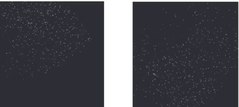
Figure 4 displays the final synthetic images generated for 3D Beltrami viewed by camera 1 (4-left) and 2D Kovasznay viewed by camera 5 (4-right). The number of particles is considered 1000 in a virtual space of dimensions 1000 mm (X) × 1000 mm (Y) × 700 mm (Z).
3. Discussion
The minimum number of similar images defined in the similarity criterion, here set at three, depends on the camera’s frame rate. For the higher frame rates, a higher number of images is considered for evaluating the particle displacements. As all the cameras are synchronous, only the positions with equal time steps are compared, which simplifies and saves time for the linking algorithm. It also implies that the instances verifying the similarity criterion are tested for successive fames. Moreover, simultaneously captured images ensure that the linking procedure is valid, regardless of the direction of the movement of a particle. It is also worth mentioning that the reliability of the linking trajectories algorithm highly depends on the accuracy of the calibration similar to the algorithms of a single 3D-PTV system.
4. Conclusion
In this study, we suggest a method to use multiple 3D-PTV systems applicable to large enclosures such as conference rooms. Several 3D-PTV systems located next to each other are utilized to cover the entire volume measured. The calibration of the cameras is described to define a common 3D coordinate system for the particle trajectories. An algorithm for linking the particle trajectories is developed based on a similarity criterion. Another limitation of using multi 3D-PTV is the higher computational time needed for computing the 3D trajectories. Several hours should be spent to calculate a few tens of images along with a few thousands of particles with a general computer. In order to reduce the computational time, a parallelized programming method will be utilized by the aid of FPGAs as a future study. The performance of this algorithm will be also investigated in the experimental data of two 3D-PTV systems. The final objective of our work is to resolve these limitations to obtain a real-time 3D-PTV that can be used as a whole-package facility applicable for building sciences.
5. Bibliography
[SUN 07] Sun Y and Zhang Y. An overview of room air motion measurement: technology and application. 2007; 13: 929–950.
[POP 98] Popiolek Z, Mierzwinski S., Humik M., Wojciechowski J., (1998), Air flow characteristic in scale models of room ventilation.
Proceedings of the Sixth International Conference on Air Distribution in Rooms, vol. 1, pp. 287–293.
[WAS 99] Wasiolek, P.T., Whicker, J.J., Gong, H. and Rodgers, J.C., 1999. Room airflow studies using sonic anemometry. Indoor Air, 9(2). [CAO 14] Cao, X., Liu, J., Jiang, N. and Chen, Q., 2014. Particle image velocimetry measurement of indoor airflow field: A review of the
technologies and applications. Energy and Buildings, 69, pp.367-380.
[ADR 91] Adrian, R.J., 1991. Particle-imaging techniques for experimental fluid mechanics. Annual review of fluid mechanics, 23(1), pp.261-304.
[KIM 12] Kim, H., Westerweel, J. and Elsinga, G.E., 2012. Comparison of Tomo-PIV and 3D-PTV for microfluidic flows. Measurement
Science and Technology, 24(2), p.024007.
[BIW 09] Biwole, P.H., Yan, W., Zhang, Y. and Roux, J.J., 2009. A complete 3D particle tracking algorithm and its applications to the indoor airflow study. Measurement Science and Technology, 20(11), p.115403.
[HEI 97] Heikkila, J. and Silven, O., 1997, June. A four-step camera calibration procedure with implicit image correction. In cvpr (Vol. 97, p. 1106).
[BEA 92] Beardsley, P. and Murray, D., 1992. Camera calibration using vanishing points. In BMVC92 (pp. 416-425). Springer. [ZHA 99] Zhang, Z., 1999, Flexible camera calibration by viewing a plane from unknown orientations. In Iccv (Vol. 99, pp. 666-673). [BOU 04] Bouguet, J.Y., 2004. Camera calibration toolbox for matlab. http://www. vision. caltech. edu/bouguetj/calib_doc/index. html. [ETH 94] Ethier, C.R. and Steinman, D.A., 1994. Exact fully 3D Navier–Stokes solutions for benchmarking. International Journal for
Numerical Methods in Fluids, 19(5), pp.369-375.