Low temperature diode pumped active mirror
Yb
3+
:YAG disk laser amplifier studies
Samuel Marrazzo,1,2,3,* Thierry Gonçalvès-Novo,1,2 François Millet,4,5 and Jean-Christophe Chanteloup1,2
1LULI - CNRS, Ecole Polytechnique, CEA, Université Paris-Saclay, F-91128 Palaiseau cedex, France 2Sorbonne Universités, UPMC Univ. Paris 06, CNRS, Laboratoire d’Utilisation des Lasers Intenses (LULI), Place
Jussieu, 75252 Paris cedex 05, France
3Amplitude Technologies, 2 Rue du Bois Chaland, 91090 Lisses, France 4Univ. Grenoble Alpes, INAC-SBT, F-38000 Grenoble, France
5CEA, INAC-SBT, F-38000 Grenoble, France
*samuel.marrazzo@polytechnique.edu
Abstract: An experimental study of a static helium gas gap heat switch
concept for laser amplification is presented. High single pass gains with large co-sintered ceramic Yb:YAG disks are recorded in the 80-200K temperature range on a diode pumped active mirror amplifier.
©2016 Optical Society of America
OCIS codes: (140.3460) Lasers; (140.3580) Lasers, solid-state; (140.3615) Lasers, ytterbium; (140.6810) Thermal effects.
References and links
1. J. Hein, S. Podleska, M. Siebold, M. Schnepp, M. Hornung, G. Quednau, M. Hellwing, R. Bödefeld, R. Sauerbrey, D. Ehrt, and W. Wintzer, “Diode pumped chirped pulse amplification to the joule level and beyond,” in Advanced Solid-State Photonics (TOPS), C. Denman and I. Sorokina, eds., (Optical Society of America, 2005), paper 762.
2. A. Bayramian, P. Armstrong, E. Ault, R. Beach, C. Bibeau, J. Caird, R. Campbell, B. Chai, J. Dawson, C. Ebbers, A. Erlandson, Y. Fei, B. Freitas, R. Kent, Z. Liao, T. Ladran, J. Menapace, B. Molander, S. Payne, N. Peterson, M. Randles, K. Schaffers, S. Sutton, J. Tassano, S. Telford, and E. Utterback, “The Mercury project: a high average power, gas-cooled laser for inertial fusion energy development,” Fus. Sci. Technol. 52, 383–387 (2007).
3. R. Yasuhara, T. Kawashima, T. Sekine, T. Kurita, T. Ikegawa, O. Matsumoto, M. Miyamoto, H. Kan, H. Yoshida, J. Kawanaka, M. Nakatsuka, N. Miyanaga, Y. Izawa, and T. Kanabe, “213 W average power of 2.4 GW pulsed thermally controlled Nd:glass zigzag slab laser with a stimulated Brillouin scattering mirror,” Opt. Lett. 33(15), 1711–1713 (2008).
4. J.-C. Chanteloup, D. Albach, A. Lucianetti, T. Novo, and B. Vincent, “6.6 J / 2 Hz Yb:YAG diode-pumped laser chain activation,” in Advances in Optical Materials, OSA Technical Digest (CD) (Optical Society of America, 2011), paper ATuE4.
5. J. Koerner, J. Hein, M. Kahle, H. Liebetrau, M. Kaluza, and M. Siebold, “High efficiency nanosecond pulse amplification based on diode-pumped cryogenic-cooled Yb:YAG,” in Advances in Optical Materials, OSA Technical Digest (CD) (Optical Society of America, 2011), paper ATuE2.
6. M. Divoky, P. Sikocinski, J. Pilar, A. Lucianetti, M. Sawicka, O. Slezak, and T. Mocek, “Design of high-energy-class cryogenically cooled Yb3+:YAG multislab laser system with low wavefront distortion,” Opt. Eng. 52(6), 064201 (2013).
7. T. Gonçalvès-Novo, D. Albach, B. Vincent, M. Arzakantsyan, and J.-C. Chanteloup, “14 J/2 Hz Yb3+:YAG diode pumped solid state laser chain,” Opt. Express 21(1), 855–866 (2013).
8. M. Siebold, M. Loeser, G. Harzendorf, H. Nehring, I. Tsybin, F. Roeser, D. Albach, and U. Schramm, “High-energy diode-pumped D2O-cooled multislab Yb:YAG and Yb:QX-glass lasers,” Opt. Lett. 39(12), 3611–3614 (2014).
9. S. Banerjee, K. Ertel, P. D. Mason, P. J. Phillips, M. De Vido, J. M. Smith, T. J. Butcher, C. Hernandez-Gomez, R. J. S. Greenhalgh, and J. L. Collier, “DiPOLE: a 10 J, 10 Hz cryogenic gas cooled multi-slab nanosecond Yb:YAG laser,” Opt. Express 23(15), 19542–19551 (2015).
10. M. Divoky, S. Tokita, S. Hwang, T. Kawashima, H. Kan, A. Lucianetti, T. Mocek, and J. Kawanaka, “1-J operation of monolithic composite ceramics with Yb:YAG thin layers: multi-TRAM at 10-Hz repetition rate and prospects for 100-Hz operation,” Opt. Lett. 40(6), 855–858 (2015).
11. G. I. Peters and L. Allen, “Amplified spontaneous emission 0.1.threshold condition,” J. Phys. A 4(2), 238–243 (1971).
12. L. Allen and G. I. Peters, “Amplified spontaneous emission and external signal amplification in an inverted medium,” Phys. Rev. A 8(4), 2031–2047 (1973).
13. J.-C. Chanteloup and D. Albach, “Current status on high average power and energy diode pumped solid state lasers,” IEEE Photonics J. 3(2), 245–248 (2011).
14. D. Albach, T. Novo, B. Vincent, and J. Chanteloup, “Beyond the current 10J energy level for the Lucia laser system with a cryogenically cooled second amplifier head,” in Lasers, Sources, and Related Photonic Devices, OSA Technical Digest (CD) (Optical Society of America, 2012), paper AW4A.16.
15. D. Albach, G. LeTouzé, and J.-C. Chanteloup, “Deformation of partially pumped active mirrors for high average-power diode-pumped solid-state lasers,” Opt. Express 19(9), 8413–8422 (2011).
16. D. Albach, J.-C. Chanteloup, and G. Touzé, “Influence of ASE on the gain distribution in large size, high gain Yb3+:YAG slabs,” Opt. Express 17(5), 3792–3801 (2009).
17. S. Guch, Jr., “Parasitic suppression in large aperture disk lasers employing liquid edge claddings,” Appl. Opt. 15(6), 1453–1457 (1976).
18. K. Ertel, C. Hooker, S. J. Hawkes, B. T. Parry, and J. L. Collier, “ASE suppression in a high energy Titanium sapphire amplifier,” Opt. Express 16(11), 8039–8049 (2008).
19. T. Gonçalvès-Novo, B. Vincent, and J. Chanteloup, “From 10 to 30 joules with the Lucia laser system: update on current performance and cryogenic amplifier development,” in Advanced Solid-State Lasers Congress, OSA Technical Digest (online) (OSA, 2013), paper ATu3A.19.
20. H. Yagi, J. Bisson, K. Ueda, and T. Yanagitani, “Y3Al5O12 ceramic absorbers for the suppression of parasitic oscillation in high-power Nd:YAG lasers,” J. Lumin. 121(1), 88–94 (2006).
21. D. Albach, T. Gonçalvès-Novo, and J.-C. Chanteloup, “Experimental cross evaluation of large size ceramic and crystalline Yb3+:YAG laser gain media performance at high average power,” Plasma Fusion Res. 8(0), 3405049 (2013).
22. A. Ikesue, O. Kinoshita, K. Kamata, and K. Yoshida, “Fabrication and optical properties of high-performance polycrystalline Nd:YAG ceramics for solid-state lasers,” J. Am. Ceram. Soc. 78(4), 1033–1040 (1995). 23. K. Ueda, J.-F. Bisson, H. Yagi, K. Takaichi, A. Shirakawa, T. Yanagitani, and A. A. Kaminskii, “Scalable
ceramic lasers,” Laser Phys. 15(7), 927–938 (2005).
24. J. Akiyama, Y. Sato, and T. Taira, “Laser ceramics with rare-earth-doped anisotropic materials,” Opt. Lett. 35(21), 3598–3600 (2010).
25. D. Albach and J.-C. Chanteloup, “Large size crystalline vs. co-sintered ceramic Yb3+:YAG disk performance in diode pumped amplifiers,” Opt. Express 23(1), 570–579 (2015).
26. A. Lucianetti, D. Albach, and J.-C. Chanteloup, “Active-mirror-laser-amplifier thermal management with tunable helium pressure at cryogenic temperatures,” Opt. Express 19(13), 12766–12780 (2011). 27. L. Duband, “A thermal switch for use at liquid helium temperature in space-born cryogenic systems,”
Cryocoolers 8, 731 (1995).
28. G. O. Jones, “A thermal switch for use at low temperature,” J. Sci. Instrum. 28(6), 181 (1951).
29. D. Albach, M. Arzakantsyan, G. Bourdet, J.-C. Chanteloup, P. Hollander, and B. Vincent, “Current status of the Lucia laser system,” J. Phys. Conf. Ser. 244(3), 032015 (2010).
30. D. Albach, J.-C. Chanteloup, and G. Le Touzé, “Amplified spontaneous emission in large size, high gain Yb3+:YAG amplifiers: numerical modeling and experimental test bench for foreseen kJ-range diode pumped solid state laser facilities,” in Conference on Lasers and Electro-Optics/Quantum Electronics and Laser Science Conference and Photonic Applications Systems Technologies, OSA Technical Digest (CD) (Optical Society of America, 2008), paper CFQ2.
31. J.-C. Chanteloup, M. Arzakantsyan, and S. Marrazzo, “Defining the optimal gradient doped:YAG disk for room and low temperature diode pumped solid-state laser operations,” High Power Laser Sci. Eng. 2, e35 (2014). 32. J.-C. Chanteloup, D. Albach, F. Assémat, S. Bahbah, G. Bourdet, P. Piatti, M. Pluvinage, B. Vincent, G. Le
Touzé, T. Mattern, J. Biesenbach, H. Müntz, A. Noeske, and R. Venohr, “Wavelength tunable, 264 J Laser diode array for 10 Hz/1ms Yb:YAG pumping,” in Fifth International Conference on Inertial Fusion Sciences and Application (IFSA, 2007), paper 032056.
33. T. Y. Fan, D. J. Ripin, R. L. Aggarwal, J. R. Ochoa, B. Chan, M. Tilleman, and J. Spitzberg, “Cryogenic Yb3+-doped solid-state lasers,” IEEE J. Sel. Top. Quantum Electron. 13(3), 448–459 (2007).
34. D. C. Brown, R. L. Cone, Y. Sun, and R. W. Equall, “Yb: YAG absorption at ambient and LF cryogenic temperatures,” IEEE J. Sel. Top. Quantum Electron. 11(3), 604–612 (2005).
35. Spectroscopic data provided by Joachim Hein and Jörg Körner, Friedrich Schiller University Jena, Department of Optics and Quantum Electronics, Jena, Thuringia, Germany.
1. Introduction
High average power and energy Diode-Pumped Solid-State Lasers (DPSSL) have been driving strong and continuous interest among the laser physicist community over the past decade. Whereas early stage work on DPSSL was confined on room temperature operated programs [1–4] with a still un-surpassed record average power set at 550W (55J/10Hz) with the Mercury project [2], a crucial shift took place in the recent years when almost all teams
moved towards DPSSL chains relying on at least one low temperature (100 to 200K) operated amplifier [5–10].
Tradeoffs between thermal management, extraction efficiency, Laser damage threshold and Amplified Spontaneous Emission (ASE) [11,12] management are at the core of DPSSL amplifier engineering and design [13]. The Laboratoire pour l’Utilisation des Lasers Intenses (LULI) has been engaged in the development of a DPSSL chain named Lucia where
amplifying stages rely on Yb3+:YAG active mirrors cooled from the High Reflectivity (HR)
coated back surface [7,14].
Thermal and ASE issues specific to this architecture are detailed in [15,16]. The mitigation of ASE deleterious effect (like parasitic lasing) can be performed through several well-known approaches [17–19] when operation takes place at room temperature. On the other hand, operating in the 100-200K range makes it almost inevitable to rely on co-sintered
Cr4+/Yb3+:YAG ceramics [20,21]. Transparent laser ceramics [22] have been made available
in large size only recently [23]. Although it offers interesting perspectives in terms of laser gain media engineering [24], a recent cross evaluation study [25] of crystalline versus ceramic Yb:YAG amplifier disks pointed out how sensitive to stress (mechanical or thermal) ceramics could be. A careful thermal management minimizing thermal stress is indeed requested to make sure a ceramic based Yb:YAG medium will not totally depolarize the beam it aims at amplifying.
Within the Lucia project, a cooling approach based on a static helium gas gap acting as the heat transport medium between the hot YAG disk and a heatsink was proposed [26]. This thermal management concept is known as a “heat switch” or “thermal switch” [27,28] which allows controlling the heat-conduction paths in the enclosed helium thin layer and consequently the Yb:YAG medium temperature. Based on this architecture, we have built a prototype laser head minimizing the radial temperature gradient generating thermal lens or depolarization through birefringence. This paper describes this active mirror amplifier prototype based on this concept and its qualification in terms of thermal management and gain performances.
2. Low temperature active mirror amplifier cooled with a static helium gas gap 2.1 Thermal management principle
While Lucia DPSSL chain first active mirror amplifier is cooled with high pressure water jets directed towards the reflecting surface [7], a fundamentally different solution has been devised [26] for this low-temperature amplifier. The idea is to rely on static helium gas enclosed into a thin (<100 µm) cell while the pressure is adjusted at a level below atmospheric pressure. This is very different from the cooling technique originally developed for Mercury [2] and later implemented in DiPOLE [9] DPSSLs for instance. In these cases, the amplifier heads are indeed cooled with a high velocity helium flow circulating in between several Yb doped slabs; and special care is requested in the design to minimize vibrations and helium pollution. Lucia low temperature amplifier head does not face such considerations and the gain medium is preserved from being altered by impurities and vibrations potentially carried by the helium forced flow.
The principle is based on the dependence of helium thermal conductivity k with the temperature T, the pressure p and the gas gap thickness e as illustrated in the formula:
1 1 2 ( ) 8 1 1 ( ) ( ) 1 1 3 3 bulk bulk k T T k T k T e p R T
α α
− ⋅ = ⋅ + ⋅ ⋅ + − ⋅ ⋅ ⋅ ⋅ where kbulk (T) is the helium bulk conductivity, R is the specific gas constant for Helium and α1 and α2 are the thermal accommodation factors [26].
Within the helium layer located between the cold source (copper at the temperature of
liquid nitrogen (LN2), 77 K) and the hot source (the Yb:YAG subjected to the pump laser
flux), the thermal exchanges occur through two processes: He wall and molecule-molecule interactions (Fig. 1).
Fig. 1. Schematic illustration of heat transfer processes at work between faces of a helium filled cavity.
The prevalence of one of these two processes (or its simultaneous occurrence) is related to
p and T for a given gas gap thickness e. Calculating the molecules mean free path Λ as a
function of these variables allows to define three different heat conduction regimes: Viscous (Λ << e), transition (e/10< Λ <10e) and free molecular (Λ >> e) regimes as illustrated in Fig. 2.
Fig. 2. Thermal conductivity of Helium as a function of pressure for temperature of 160 K (plain lines) and 300 K (dashed lines) and various Helium gap thicknesses.
2.2 Co-sintered ceramics as gain medium disk
Taking advantage of Yb reabsorption at 1030 nm was proven to be quite efficient to mitigate ASE-triggered effect like parasitic oscillations when operating a Yb:YAG amplifier in the vicinity of room temperature [29, 30]. However, when operation below 150K is requested, 1030 nm reabsorption almost vanishes (cross section < 5.10−22 cm2) as illustrated in [31].
Absorbing spontaneously emitted radiations at this temperature level therefore requires a
YAG disk with a Cr4+ doped periphery. In order to investigate that approach, a first
generation of Cr4+/Yb3+:YAG cosintered ceramic was manufactured by Konoshima, Japan
(Fig. 3, left) where the Cr4+ doped radial thickness is 5 mm whereas doping concentration is
a too high Cr4+ doping concentration due to a 6 cm−1 linear absorption coefficient (Table 1).
The absorption power was indeed too strong and the resulting heat load located at the Cr4+/Yb3+ interface generated internal stress [21, 25]. A second generation of 3 disks (Fig. 3,
right) was then processed with a 4x larger Cr4+ doped radial thickness of 20 mm coupled to
~4x reduction in absorption coefficient (Table 1). The actual doping level, very likely below 0.1at%, was not made available by the manufacturer. Whereas one side is AR coated, the other (in contact with Helium) is HR coated, both for pump (940 nm) and extraction (1030 nm) wavelengths.
Fig. 3. Illustration of both generations of Cr4+/Yb3+:YAG co-sintered ceramics.
Table 1. Co-sintered ceramics specifications. Ceramics Thickness Yb3+ doped Ø Cr4+ doped Ø Cr4+ doped radial thickness t Yb3+ doping Cr4+ doping Absorption coefficient Transmission over t
Unit mm mm mm mm at% at% cm−1 %
Generation 1 7 35 45 5 2 0.25 6 4.98 Generation 2-A 10 37 77 20 1 known not 2.92 0.29 Generation 2-B 1.65 3.71 Generation 2-C 1.58 4.24
2.3. Laser head description
The Lucia water cooled first laser head used to reach the 14 J milestone [7] is pumped at a
rather high intensity level (15 to 20 kW/cm2) [32]. The high emission cross section of
Yb:YAG at low temperature [33, 34] allows a significant reduction in pump budget and this second laser head requires therefore only 5.5 kW/cm2 (~1 ms pulse duration) within a 6 cm2
homogeneously filled elliptical footprint (43 kW Lastronics pump engines with 76% efficiency).
Figure 4 details the head where a first copper block, as heatsink, is brazed on a LN2 filled
Dewar. For operation/maintenance purpose, a second removable copper element is screwed onto the first one; a ~100 µm layer of Indium ensures an efficient thermal contact. The other face of that copper element is carefully rectified and acts as one wall of the low pressure helium gas gap. The second wall is the HR coated side of the YAG disk. The pressure in the helium gas gap is adjusted to the required one with a vacuum pump and a source of helium gas. The thickness of the helium layer is fixed by the thickness of a thermal insulating
element made of polyimide (VESPEL®) and the torque applied to the disk mount screws
applying pressure on a pair of metallic seals. These later seals (HELICOFLEX®) are
specifically designed to prevent any helium leaks even at low temperature. The removable copper element hosts also a set of heating cartridges giving an extra degree of freedom for
temperature control. For instance these cartridges can be used to set the initial temperature at the desired value (i.e. above the ~90K at which the gain medium is usually thermalized before pumping starts).
Fig. 4. CAD section view of the low temperature laser head. 3. Experimental qualifications
3.1 Thermal
In order to validate the thermal management concept exposed in section 2.1 and [26], it was necessary to have access to the gain medium surface and inner temperatures. For this purpose, two 15 mm deep holes were drilled at 3 and 7 mm depth on the periphery of a 77 mm diameter 2 at% doped Yb:YAG crystal of 10 mm thickness. Platinum PT100 probes were inserted in both holes while a thermocouple was strapped onto a thin annular copper disk placed on the top (altitude 0 mm i.e. AR coating surface) of the YAG crystal as illustrated on Fig. 5.
Fig. 5. Left, picture of a Yb:YAG crystal in its mount. The three thermal probes allow temperature measurement at 0, 3 and 7 mm depths. While the amplifier is operated at 1, 2 and 5 Hz, a below 5K axial gradient is observed. Helium pressure is set at 700 mbar, gap thickness at 400 µm while pump intensity reaches 5.5 kW/cm2 homogeneously distributed over the pump area illustrated in red on left picture.
An axial temperature gradient below 5K was observed. However it must be kept in mind that these measurements are performed a couple of centimeters away from the central illuminated part. It therefore does not give information about the gradient experienced by the crystal where the heat load is at its maximum, i.e. at its center. But the main purpose of this experiment was to identify the optimum range of pressure sensitivity as illustrated on Fig. 6.
We confirm a sensitive pressure range between 1 and 10 mbar. Above that level, the helium layer thermal conductivity is not evolving anymore as illustrated in Fig. 2 and therefore allows cooling control around 130K for a 2 Hz pump rate. Similar experiments were performed with a much thinner gas gap of 55 µm and an identical pump intensity of 5.5
kW/cm2 for which a minimal cooling temperatures of 110K (5Hz, 27.5W/cm2) and 150K (10
Hz, 55W/cm2) were achieved.
It should also be pointed out that this experimental configuration allowed us to record Yb:YAG absorption cross sections between 80 and 300 K as illustrated on Fig. 2 of [31].
Fig. 6. Yb:YAG ceramic temperature versus helium pressure in a static 400 µm thick cell. Iso-mean free path (MFP) curves are displayed for 40, 4 and 0.4 µm. The first one defines the limits between transition (blue) and viscous (green) regimes as defined in section 2.1. Data points were collected while the 5.5 kW/cm2 pump intensity was delivered at 2 Hz with a 1 ms pulse duration.
3.2 Gain
[25] was dedicated at cross evaluation of 45 mm diameter co-sintered ceramics (Generation 1) and crystals at room temperature. This new prototype allows us to extend that study by comparing 77 mm disks operated at low temperature. A narrow (<0.1nm) 1030.3 nm CW 60 mW laser source was first used as a probe beam. Experimental conditions were identical for both disks.
The Yb:YAG crystal performances are clearly affected by the lack of ASE control scheme (no 1030 nm absorption of Yb at these temperatures and absence of Cr ions playing a similar role). After a few hundreds of microseconds, strong gain saturation takes place. Even at relatively high (200K) temperature, the gain never exceed a value of 2 (left, Fig. 7). These
ASE plateaus are not observed on the Cr4+/Yb3+:YAG co-sintered ceramic gain curves and a
50% increase in single pass gain can be attained (right, Fig. 7). For these graphs and the followings, the reported temperatures are recorded through a peripheral copper ring in contact with the AR coated surface of the YAG disk.
Fig. 7. Single pass gain temporal behavior for two 1 cm thick, 77 mm in diameter Yb:YAG disks operated in the low temperature Lucia amplifier. The 5.5 kW/cm2 pump is limited at 1 ms duration (blue area) with a 2 Hz repetition rate. The left graph pictures gain curves obtained in the crystal case while the right graph is dedicated to the co-sintered ceramic. The Helium gas gap thickness is 150+/−5 µm.
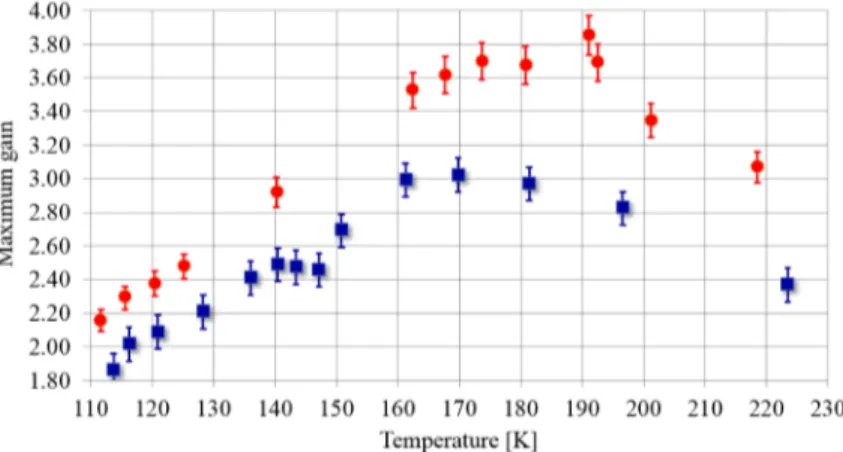
Maximum gain values recorded with the ceramics are reported on Fig. 8 for different adjusted pressures in the gas gap (i.e. temperature control). The blue square are the maxima of Fig. 7 right graph curves (2 Hz, 150 µm) whereas the red circles have been obtained similarly while operating the amplifier at 5 Hz with a 55 µm thickness Helium gap). The single pass gains increase with decreasing temperature until a temperature in the 160-190 K range where it somehow saturates and then decreases. In order to explain this behavior, one could invoke ASE losses but, although likely to play a negative role, ASE does not appear to play a significant one when carefully looking at build-up phase at Fig. 7 (right image). The reason has in fact to be linked to the nature of the source used for this experiment, i.e. a 1030.3 nm narrow one.
Fig. 8. Maximum gain observed versus Cr4+/Yb3+:YAG co-sintered ceramic temperature. Extraction wavelength is 1030.3 nm. Pump intensity is 5.5 kW/cm2 with 1 ms pulse duration. The blue squares are the maximum values observed on Fig. 7 (right), i.e. obtained at 2 Hz with a 150+/−5 µm Helium gas gap thickness. The red disks are gain maxima obtained at 5 Hz with a 55+/−5 µm gap.
Figure 9 shows that, in order to reach much higher gains, a source tunable down to 1029.5 nm is requested.
Fig. 9. Maximum emission cross section (red, left scale) and wavelength allowing to reach that maximum (green, right scale) versus temperature. Reaching high cross section values around 1.10−19 cm2 requires a 1029.5 nm source. This graph was derived from data kindly shared by [35].
Fig. 10. Small signal gain recorded at 1029.7 nm while pumping the Cr4+/Yb3+:YAG co-sintered ceramic at 5.5kW/cm2 intensity and single shot, 0.5, 1 and 2 Hz repetition rate. Respective temperatures are 84, 98, 117, 142 K. Helium pressure is 1 bar.
Gain measurements were then performed while adjusting the wavelengths to better match emission cross section maxima. Figure 10 displays single pass gain obtained with a 1029.7 nm narrow (100 pm) 35 mW CW source. Gain values vary between 12 and 20 with YAG temperatures across the 142 to 84 K range.
Similar experiment where performed with Lucia front end nominal configuration with a 20 mm diameter beam of 10 ns pulses at 2 Hz at 1029.7 nm; maximum energy per pulse being half a Joule. Figure 11 shows that single pass gain stays above 6 in the 100 to 460 mJ explored energy range. The YAG temperature was close to 140K.
Fig. 11. Left, blue: single pass gain recorded in pulse mode (10 ns / 2 Hz) with the Cr4+/Yb3+:YAG co-sintered ceramic. Right, Red: Amplified energy in a single pass.
Any Helium pressure adjustment imposes a temperature stabilization period which depends of the operating pressure range (1, 10 or 100 mbar). A ~1% stabilization can require up to half an hour. As soon as the point of operation is defined (helium gap thickness, pressure, pump load…), it should not be necessary to adjust the helium pressure.
6. Conclusions
We have experimentally validated at low temperature the static helium gas gap heat switch concept for active mirror laser amplifier. A prototype was built and integrated into the Lucia laser chain. It can host YAG disks up to 77 mm in diameter in an active mirror configuration. A simple helium pressure adjustment between 1 and 10 mbars allows us to explore the amplifier behavior over a 100K wide temperature range around 140K. Colder or warmer operating temperatures could be achieved easily by adjustment of the VESPEL ring thickness allowing the helium layer to be tuned from tens of µm to hundreds of µm.
Thanks to Konoshima optimization work in terms of ultralow Cr4+ doping concentration, a
new generation of co-sintered Cr4+/Yb3+:YAG disks were used allowing a 2x single pass gain
improvement from 3 to around 7. Foreseen evolution of this low temperature amplifier will be devoted to a 2nd generation amplifier able to operate in the same temperature range without the need of LN2.
Acknowledgments
The research leading to these results has received funding from LASERLAB-EUROPE (grant agreements no. 228334 and n° 284464, EC's Seventh Framework Programme). The authors thank J. Hein and J. Körner for sharing emission cross section data used for Figs. 8 and 9.