Publisher’s version / Version de l'éditeur:
Surface & Coatings Technology, 201, 14, pp. 6278-6284, 2007-01-02
READ THESE TERMS AND CONDITIONS CAREFULLY BEFORE USING THIS WEBSITE. https://nrc-publications.canada.ca/eng/copyright
Vous avez des questions? Nous pouvons vous aider. Pour communiquer directement avec un auteur, consultez la première page de la revue dans laquelle son article a été publié afin de trouver ses coordonnées. Si vous n’arrivez pas à les repérer, communiquez avec nous à PublicationsArchive-ArchivesPublications@nrc-cnrc.gc.ca.
Questions? Contact the NRC Publications Archive team at
PublicationsArchive-ArchivesPublications@nrc-cnrc.gc.ca. If you wish to email the authors directly, please see the first page of the publication for their contact information.
NRC Publications Archive
Archives des publications du CNRC
This publication could be one of several versions: author’s original, accepted manuscript or the publisher’s version. / La version de cette publication peut être l’une des suivantes : la version prépublication de l’auteur, la version acceptée du manuscrit ou la version de l’éditeur.
For the publisher’s version, please access the DOI link below./ Pour consulter la version de l’éditeur, utilisez le lien DOI ci-dessous.
https://doi.org/10.1016/j.surfcoat.2006.11.026
Access and use of this website and the material on it are subject to the Terms and Conditions set forth at
Properties of alumina–titania coatings prepared by laser-assisted air
plasma spraying
Dubourg, L.; Lima, R. S.; Moreau, C.
https://publications-cnrc.canada.ca/fra/droits
L’accès à ce site Web et l’utilisation de son contenu sont assujettis aux conditions présentées dans le site LISEZ CES CONDITIONS ATTENTIVEMENT AVANT D’UTILISER CE SITE WEB.
NRC Publications Record / Notice d'Archives des publications de CNRC:
https://nrc-publications.canada.ca/eng/view/object/?id=bac13786-3604-4b4b-8dc8-aef6d9b3826d https://publications-cnrc.canada.ca/fra/voir/objet/?id=bac13786-3604-4b4b-8dc8-aef6d9b3826dProperties of alumina–titania coatings prepared by
laser-assisted air plasma spraying
L. Dubourg
⁎
, R.S. Lima, C. Moreau
Industrial Material Institute, National Research Council of Canada, 75 de Mortagne Blvd., Boucherville, Quebec, Canada J4B 6Y4
Received 3 August 2006; accepted in revised form 22 November 2006 Available online 2 January 2007
Abstract
Studies have shown that microstructures formed by post-laser remelting of air plasma sprayed coatings exhibit densification but also numerous macrocracks due to the rapid cooling and thermal stresses. In laser-assisted air plasma spraying (LAAPS) process, the laser beam interacts simultaneously with the plasma torch in order to increase the temperature of the coating and possibly remelt the coating at the surface. As a result, the microstructure is partially densified and macrocracks, which are generally produced in the post-laser irradiation treatment, may be inhibited. In this paper, LAAPS was performed to improve the hardness and wear resistance of Al2O3–13%TiO2 coatings. These coatings prepared by air
plasma spraying (APS) are widely used to protect components against abrasive wear at low temperatures. The coating microstructure was characterized by SEM and X-ray diffraction. The mechanical characterization was done by hardness measurements, erosive wear tests and abrasion wear tests. Results showed that laser assistance may improve the microstructural and mechanical properties. Phenomena involved in LAAPS of alumina–titania coatings are discussed in this paper.
© 2006 Elsevier B.V. All rights reserved.
Keywords: Laser-assisted air plasma spraying; Alumina–titania; Erosive wear; Abrasive wear
1. Introduction
Alumina–titania coatings produced by air plasma spraying (APS) are widely used to protect components against abrasive
wear at low temperatures[1–3]. However, APS ceramic coatings
contain connected porosities and the properties of these coatings, such as high temperature corrosion resistance, toughness and abrasive resistance, may thereby be reduced. To improve these properties, various methods have been proposed, such as im-pregnation with polymers or ceramics, seal sintering with liquid alloys and post-laser irradiation[4–12]. Laser irradiation may be an interesting method for densifying the microstructure of the ceramic coatings. However, in post-spraying configuration, i.e. the laser treats the coating after its deposition, the formation of
macrocracks is difficult to be suppressed [4,6–8,10,13,14].
During rapid solidification after the laser irradiation, the contraction of a high material volume induces stresses into the coating. These stresses are finally relaxed by the formation of macrocracks. Laser-assisted air plasma spraying (LAAPS) consists of APS with the simultaneous laser beam irradiation, the APS gun and the laser head being coupled. This method has
been studied to deposit ZrO2ceramic with Ni-based bond coat
[4–7,13,14], Cr3C2cermets[15], Al2O3based ceramic[1,12,16]
and TiNi metallic alloy[17]. This process enables control of the coating microstructure in a single process. Molten and semi-molten particles are sprayed from a plasma torch, and the heat of the particles impinging on the substrate may be controlled by laser irradiation depending on the laser parameters. According to recent studies, LAAPS seems to be effective in preventing the formation of macrocracks and in maintaining an appropriately
densified microstructure[4–7,13,14]. The remelted thickness in
one pass is lower in the case of LAAPS than in the case of laser post-treatment. Consequently, the stresses induced during the layer solidification are lower and the macrocrack appearance may be inhibited. In this study, alumina–titania coatings were prepared by laser-assisted air plasma spraying using a
www.elsevier.com/locate/surfcoat
⁎ Corresponding author. Current address: Aerospace Manufacturing Technol-ogy Centre, National Research Council Canada, 5145 avenue Decelles, Montréal, Quebec, Canada H3S 2S4. Tel.: +1 514 283 7997; fax: +1 514 283 9445.
E-mail address:laurent.dubourg@cnrc-nrc.gc.ca(L. Dubourg). 0257-8972/$ - see front matter © 2006 Elsevier B.V. All rights reserved. doi:10.1016/j.surfcoat.2006.11.026
continuous 2 kW Nd:YAG laser. Wear resistance properties were evaluated in relation to changes in the coating microstructure. The properties of such coatings were compared with those of as-sprayed APS coatings.
2. Experimental set-up
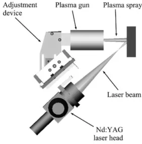
Fig. 1shows the experimental set-up of LAAPS. The laser head and the APS gun (SG100, Praxair, Concord, NH, USA) were coupled on a 6-axis robot and move at a transverse speed of
0.6 m s− 1. The laser beam was adjusted at the centre of the
particle footprint on the substrate surface (particle footprint of around 10-mm diameter). The particle stream was almost normal to the surface sample, while the angle between the laser beam and the plasma spray was set at 45°.
Al2O3–13%TiO2 powder (Metco 130) was used to deposit
500-μm thick coatings on low carbon steel substrates (length: 76.2 mm, width: 25.4 mm, thickness: 12.7 mm). A Ni–Cr–Al–Y 150-μm-thick bond coat (Praxair Ni-164-2 powder) was applied by APS to improve the adhesion of ceramic coatings. LAAPS was not used during the bond coat deposition. Substrates were grit-blasted before spraying. The spray parameters employed in this work are listed inTable 1. The spraying parameters of the Al2O3–
13%TiO2coating were chosen based on previous experiments
with different torches and spray parameters. All these coatings were abrasion-tested and the coating sprayed with the parameters listed inTable 1exhibited the highest abrasion wear resistance and was chosen as the benchmark for the current experiment. During spraying, a cooling system (air jets) was applied to reduce the coating temperature, which was monitored by using an optical pyrometer. The maximum coating temperature, while depositing coatings to a thickness of approximately 500 μm, did not exceed 170 °C.
LAAPS was carried out using a 2000 W continuous wave Rofin Sinar Nd:YAG laser of 1.064-μm wavelength and a 1-mm diameter optical fiber. A lens with a 200-mm focal length fo-cussed the laser beam and the laser power was adjusted to 1650 W on the workpiece surface. The laser irradiation density is
calcu-lated by the ratio of laser power applied on the sample to the surface of laser beam irradiating the sample. The changes of laser irradiation density offered during LAAPS was controlled by adjusting the out-of-focus distance of the laser beam irradiating
the specimen surface (see Fig. 1), whereas the plasma spray
parameters were maintained constant for all samples. The rela-tionship between out-of-focus distance, spot diameter of the
laser beam and laser irradiation density is shown in Table 2.
Distribution of the laser beam evolved from a top hat profile at the focus point to a gaussian profile at an out-of-focus position[4].
The coatings were vacuum-impregnated with a low viscosity epoxy and then polished to a mirror finish (diamond with grain size of 1 μm). The cross-section microstructures were evaluated via scanning electron microscopy (SEM). Phases were iden-tified by X-ray diffraction (2θ from 20° to 80°) using a Bruker AXS D8-Discover diffractometer (CuKα radiation, λ = 1542 Å, step = 0.05°, step time = 2.5 s, 40 kV, 40 mA). Vickers measure-ments were performed on coating cross-sections with a load of 3 N in the case of micro-hardness measurements (15 inden-tations per sample) and 50 N in the case of crack propagation analysis (5 indentations per sample). The slurry-erosion test was carried out using an in-house built set-up. Alumina #100 (20– 360 μm) was employed as erodent. The liquid part of the slurry was made with neutral pH deionised water and the erodent concentration was 0.66% by weight. The slurry jet had a con-stant flow rate of 1 l min− 1(6.6 g min− 1of alumina particles)
and a constant velocity of 20 m s− 1. The slurry-erosion
re-sistance was evaluated at an impinging angle of 90° during 5 min for each sample. Three samples were tested for each of the different coating types produced in the study. The volume of the material abraded away during the slurry-erosion test was measured via optical profilometry. The abrasion resistance of the coatings was tested following the ASTM standard G65-00
Fig. 1. Experimental set-up for laser-assisted air plasma spaying.
Table 1
Spray parameters used for the APS torch
Al2O3–13%TiO2 Ni–Cr–Al–Y
Plasma gun type SG100 SG100
Nozzle exit internal diameter (mm) 8 8 Powder injector internal diameter (mm) 2 2 Primary gas (Ar) flow (l min− 1) 50 50 Secondary gas (l min− 1) 1.6 (H
2) 23.6 (He)
Current (A) 800 700
Voltage (V) 38.8 35.8
Power (kW) 31 25
Carrier gas (Ar) flow (l min− 1) 7 6.5 Powder feed rate (g min− 1) 20 30
Spray distance (mm) 63 63
Table 2
Relationship between out-of-focus distance, spot diameter of the laser beam and laser irradiation density
Out-of-focus distance (mm) Spot diameter (mm) Power density (W mm− 2)
30 6 60 40 8 34 50 10 22 60 12 15 70 14 11 6279
(procedure D-modified)[18], also known as the dry sand/rubber wheel test. In this test, a stationary coated sample (coating surface) was pressed against a rotating rubber-coated wheel (114.3-mm radius — 200 rpm) with a force of 45 N. Silica sand
(212–300 μm) was fed (300–400 g min− 1) between the coating
and rubber wheel until the wheel travelled over the equivalent linear distance of 1436. Prior to being submitted to this test, the surfaces of the coatings were prepared by grinding with diamond wheels to produce a flat surface. The ground coatings
exhibited roughness values (Ra) of approximately 0.2 μm. Two
samples were tested for each types produced in the study. The volume of the material abraded away during the abrasion test
was measured via optical profilometry[19].
3. Results
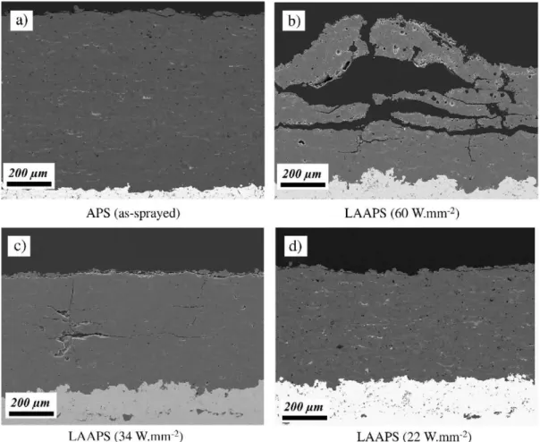
Fig. 2a shows a typical cross section of an APS alumina– titania coating. The microstructure shows lamellar splat morphology with interlamellar pores, typical of plasma
sprayed coatings. Fig. 2b, c and d show the changes of the
microstructure obtained by LAAPS at laser power densities of
60, 34 and 22 W mm− 2. A well-bonded between the coating and
the bond coat was obtained. The density of the microstructure of LAAPS coatings increased with the laser irradiation density
increasing from 11 to 60 W mm− 2. This is experimentally
observed by looking at the microstructures of an APS and a
LAAPS coating (34 W mm− 2) inFig. 3. It is noticed that under
cracks and pores were healed by using the laser-assisted deposition under optimum conditions. On the other hand, in the case of out-of-focus distance equal or lower than 30 mm, the laser irradiation density was too high, equal or superior to
60 W mm− 2. This leads to an excessive melting thickness,
inducing higher stresses and the debonding of the alumina–
titania coatings (Fig. 2b). A similar phenomenon has been
re-ported in many studies on laser remelting of APS ceramic coatings[4,6,7]. Due to the high laser density, excessive coating melting takes place under the irradiation area. Then a large contraction of the melted ceramics occurs in an extremely short period of time due to rapid cooling. This causes the appearance of large cracks parallel and normal to the sample surface and, in extreme cases, the debonding of the coating, as shown inFig. 2b. On the other hand, when the laser irradiation density
de-creases from 34 to 11 W mm− 2, the coating melting is mostly
absent and the coatings are defect-free. At 34 W mm− 2, some
cracks were still observed as shown in theFig. 2c, nevertheless
their number and size were small compared to coating processed with higher laser density. For a laser irradiation density lower
than 34 W mm− 2, these macrocracks were not observed by
optical microscopy (Fig. 2d). In this case, the contraction of
the coating during the solidification was smaller than one obtained at higher laser density as the regions of contraction were limited to the upper layers of the coating. At high
magnification (Fig. 3a), the SEM observation of an APS coating revealed intralamellar microcracks in the splats. With the LAAPS use, the intralamellar microcracks in the splats were
inhibited or strongly reduced (Fig. 3b). These microcracks can
be inhibited by the heating effect of laser irradiation. This makes the sprayed particles to cool at a slower speed, limiting the thermal stress. Moreover, the laser irradiation can partially remelt the upper layers of the alumina–titania coatings during the process. This may cause the elimination of microcracks by densification of the molten splats.
As shown inFig. 4, XRD phase analysis revealed that the
as-sprayed coating predominantly consists of the metastable
γ-Al2O3phase. The thermodynamically stable α-Al2O3phase is
present only in small quantity. Early experiments with thermally
spray alumina deposits showed that the metastable γ-Al2O3
structure was produced rather than α-Al2O3[20]. This can be
explained based on nucleation kinetics; γ-Al2O3is more easily
nucleated from the melt than α-Al2O3 because of a lower
interfacial energy between crystal and liquid and, at sufficiently rapid cooling rates, the metastable form is retained at room
temperature [20]. The same observation can be done on the
coatings obtained by LAAPS as shown in the XRD pattern of
Fig. 4a carried out with a laser irradiation density of 22 W mm− 2.
At this laser irradiation density, macrocracks were not observed
by optical microscopy (see Fig. 2d). The LAAPS coatings
mainly consist of the metastable γ-Al2O3phase. However, as
shown by the relative height and number of diffraction peaks, a
higher quantity of the stable α-Al2O3 may be formed. This
characteristic may be related to a slower solidification rate of the molten phase during spraying. Indeed, the solidification rate is reduced by the laser heating effect increased by the thermal barrier effect of the lower alumina–titania layers. As a matter of fact, the low thermal conductivity of the lower layers can reduce the heat transfer by thermal conduction, and hence decrease the solidification rate. This lower solidification rate can cause the partial equilibrium solidification and the precipitation from the metastable γ-Al2O3 to the stable α-Al2O3. The formation
of α-Al2O3 during LAAPS is highly desirable because this
phase exhibits improved mechanical properties when compared
Fig. 5. Hardness evolution of APS and LAAPS coatings as a function of the laser irradiation density. The hardness of APS coatings and its standard deviation are shown by the dark and the dash lines, respectively.
Fig. 4. XRD patterns of alumina–titania coatings obtained by a) LAAPS with a laser irradiation density of 22 W mm− 2, b) APS without laser.
Fig. 3. Cross-sectional SEM micrographs of a) as APS coating and b) LAAPS coating at 34 W mm− 2.
6281
to γ-Al2O3[21]. This may help the enhancement of the anti-wear
performance of the coatings, as shown afterwards.
Fig. 5shows the hardness in the cross section of APS alumina– titania coating (dark line) and coatings obtained by LAAPS, laser
irradiation density evolving from 11 to 34 W mm− 2. Hardness
values of LAAPS coatings obtained with a laser irradiation higher
than 13 W mm− 2 were higher than that of the APS coating
(1093 HV). The maximum value was 1210 HV, corresponding to a hardness increase of 11% compared with the APS coating. As
shown inFig. 5, the hardness increases with the increase of the
laser irradiation density. Similar observations have been reported by several authors[4,6].Fig. 5indicates a good linear correlation between hardness and laser irradiation density (r2= 0.77).
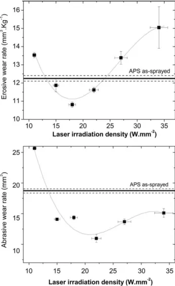
LAAPS improved the erosive wear resistance in the laser
irradiation density range of 15–22 W mm− 2, as reported in
Fig. 6a. Outside this range, the wear rate was higher than
12.2 mm3 kg− 1, the value measured on the APS coatings.
The best result was achieved for a laser irradiation density of
18 W mm− 2, leading to a wear rate of 10.8 mm3 kg− 1 and
erosion resistance improvement of 12%. Fig. 6b shows the
abrasive wear resistance evaluated on the coating surface obtained by APS and LAAPS. The volume loss of the APS
coatings was about 17.6 mm3. This value was reduced by the
LAAPS use, up to a minimum value of 11.0 mm3with a laser
irradiation density of 22 W mm− 2. The volume loss during
abrasive wear is then reduced by 38%. As shown inFig. 6b, the
volume loss decreased considerably with an increase of the laser
irradiation density from 11 to 22 W mm− 2. On the other hand,
the volume loss increased between 22 to 34 W mm− 2, although
it was always lower than the one of APS coatings. 4. Discussion
The improvement of hardness obtained using the LAAPS process can be explained by different factors. First, the sample surface temperature was raised by the laser beam irradiation. Moreover, this heating effect was increased by the thermal barrier effect of lower alumina–titania layers. This local heating may result in an increase of the substrate wettability to the sprayed particles, an increase of the bonding areas between the splats and therefore the strengthening of the bonding force
between the splats (Fig. 3). This phenomenon was highlighted
by Kuwashima et al.[22]in the case of Cr3C2–Ni–Cr splats
deposited by laser-assisted HVOF and Jiang et al.[23]in the
case of Mo splats deposited by LAAPS. This strengthening of the bonding force between the splats can be also observed by the crack propagation measurement produced during Vickers
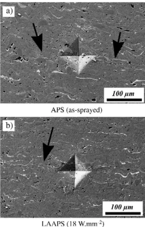
indentation[24].Fig. 7shows the formation of these cracks on
an APS coating (Fig. 7a) and a LAAPS coating (Fig. 7b); this
latter coating was obtained with a laser irradiation density of
18 W mm− 2, leading to the higher wear resistance. Five Vickers
indentations at a load of 50 N for 15 s were carried out on the cross section of each coating. The indenter is aligned such that one of its diagonals is parallel to the substrate surface. The total length of the major crack (2c) parallel to the substrate surface that originated at or near the corners of the Vickers indentation was measured. The mean crack lengths were respectively 745 μm (standard deviation of 110 μm) and 333 μm (standard deviation of 33 μm) for APS and LAAPS coatings, respectively. Based on the indentation load (P) and crack length (2c), the crack propagation resistance was calculated according to the
relation P/c3 / 2where P is in Newton and c in meter[25]. The
calculated crack propagation resistances were 7.2 MPa m1 / 2for
the APS coating and 23.6 MPa m1 / 2 for the LAAPS coating.
This strengthening improvement of the bonding force among the splats associated with the partial precipitation of α-Al2O3
instead of γ-Al2O3can explain the hardness increase in LAAPS
coatings observed inFig. 5.
The benefits of LAAPS on the erosive and abrasive wear resistance may result from the following factors. Firstly, the intralamellar microcracks in the splats were inhibited by the laser irradiation. This phenomenon decreases the fracture and the removal of the coating splats during the impacts of erosive particles or the scratch effect of the abrasive particles. Secondly, as shown previously, LAAPS resulted in the strengthening improvement of the bonding force between the splats. This
Fig. 6. Relationship between laser irradiation density and a) erosive wear rate and b) abrasive wear rate for LAAPS coatings. The wear rates of APS coatings and their standard deviation are shown by the dark and the dash lines, respectively.
decreases also the removal phenomenon of the splats during the impacts of erosive particles or the scratch effect of the abrasive
particles. Thirdly, the α-Al2O3phase with enhanced mechanical
properties is partially precipitated instead of γ-Al2O3 one.
Finally, LAAPS coatings showed a higher hardness than the APS coatings. Consequently, in the case of abrasive wear properties, this higher hardness reduces the scratch effect of the abrasive particles and, in consequence, the volume loss.
When the laser irradiation density is higher than 22 W mm− 2,
the erosive wear rate raised and became higher than the one measured on the APS as-sprayed coatings. The same phenom-enon was observed on the abrasive wear experiment, although the rate was lower than one of APS coatings. The previous benefits of LAAPS process are then balanced by the appearance of macrocracks parallel to the sample surface (seeFig. 2b and c), with the subsequent decrease of the cohesion of the coatings. During the wear tests, these macrocracks can cause the delami-nation of large debris. On the other hand, when the laser
irradiation density is lower than 15 W mm− 2, the erosive and
abrasive wear resistance is also lower than the one measured on the APS coatings. In this case, the laser irradiation density can be too low to induce the previous benefits; however, there is probably a significant increase in the temperature of the coating under the laser spot. It has been demonstrated that thermal spray ceramic coatings deposited on warm coatings/substrates tend to exhibit significant more cracking during mechanical solicitation when compared to similar coatings deposited on cooler
con-ditions [26]. Therefore, the low performance of the coatings
produced at low laser irradiation density is probably explained by their tendency of severe cracking under mechanical loading. In general, LAAPS coatings obtained with a laser density
between 15 and 22 W mm− 2 showed higher mechanical
properties than APS coatings. In this process window, LAAPS benefits seem higher than its drawbacks. Out of this range, LAAPS advantages are counterbalanced by appearance of cracks in the coatings, reducing the mechanical properties. 5. Conclusions
This study concerned the deposition of alumina–titania coatings by laser-assisted air plasma spraying using a 2 kW continuous Nd:YAG laser. The characteristics of this hybrid process were investigated, especially the effect of the laser irradiation density on the microstructure and mechanical pro-perties of alumina–titania coatings. The results are summarized as follows: (1) intralamellar and interlamellar macrocracks due to the laser irradiation were not observed by optical microscopy in the alumina–titania coatings for a laser irradiation density
lower than 22 W mm− 2; (2) microcracks in the deposited splats
were inhibited or strongly reduced; (3) the metastable γ-Al2O3
phase was partially transformed in the equilibrium α-Al2O3
phase; (4) the erosive wear resistance is improved by 12%; (5) the abrasive wear resistance is enhanced by 38% as compared to APS coatings. These improvements were observed with a laser
irradiation density between 15 and 22 W mm− 2.
Acknowledgements
The authors want to thank S. Bélanger for APS spraying, B. Harvey and M. Larouche for LAAPS spraying and erosive tests, J. F. Alarie for abrasive tests, M. Lamontagne for optical profilometry measurements, Héléne Grégoire for metallography and for her assistance with scanning electron microscopy and M. Thibodeau for his assistance with X-ray diffraction analysis. References
[1] R. Zieris, S. Nowotny, L.M. Berger, L. Haubold, E. Beyer, International Thermal Spray Conference 2003: Advancing the Science and Applying the Technology, Orlando, FL, USA, ASM International, Member/Customer Service Center, Materials Park, OH, 44073-0002, USA, 2003, p. 567. [2] R.S. Lima, A. Kucuk, U. Senturk, C.C. Berndt, J. Therm. Spray Technol.
10 (1) (2001) 179.
[3] R.S. Lima, B.R. Marple, 1st ASM International Surface Engineering Conference and the 13th IFHTSE Congress, Columbus, OH; USA, ASM International, Member/Customer Service Center, Materials Park, OH, 44073-0002, USA, 2002, p. 495.
[4] A. Ohmori, Z. Zhou, N. Eguchi, Trans. J.W.R.I. 26 (1) (1997) 99. [5] O.C. Sang, A. Ohmori, K. Nakade, Trans. J.W.R.I. 31 (2) (2002) 207. [6] Z. Zhou, H. Shirasawa, N. Eguchi, A. Ohmori, J. Therm. Spray Technol.
8 (3) (1999) 405.
[7] G. Antou, G. Montavon, F. Hlawka, A. Cornet, C. Coddet, F. Machi, Surf. Coat. Technol. 172 (2–3) (2003) 279.
[8] L. Pawlowski, J. Therm. Spray Technol. 8 (2) (1999) 279. [9] J.H. Ouyang, X. Li, J. Mater. Eng. Perform. 9 (2000) 516. [10] H.L. Tsai, P.C. Tsai, J. Mater. Eng. Perform. 7 (2) (1998) 258.
[11] R. Krishnan, S. Dash, R.K. Sole, A.K. Tyagi, B. Raj, Surf. Eng. 18 (3) (2002) 208.
Fig. 7. Cross-sectional SEM micrographs of Vickers indentations (load of 50 N): a) APS coating and b) LAAPS coating at 18 W mm− 2.
6283
[12] J.F. Li, L. Li, F.H. Stott, ICALEO International Congress on Applications of Lasers and Electro-Optics, Jacksonville FL, USA, Laser Institute of America, Orlando, FL, USA, 2003.
[13] Z. Zhou, N. Eguchi, H. Shirasawa, A. Ohmori, 15th International Thermal Spray Conference, Nice, France, vol. 2, ASM International, Member/ Customer Service Center, Materials Park, OH, 44073-0002, USA, 1998, p. 1663.
[14] G. Antou, G. Montavon, F. Hlawka, A. Cornet, C. Coddet, F. Machi, Surf. Coat. Technol. 180–81 (2004) 627.
[15] T. Kuwashima, I. Takahashi, T. Tomita, A. Ohmori, Mater. Trans. 45 (2004) 1864.
[16] J.F. Li, L. Li, F.H. Stott, Surf. Coat. Technol. 180–81 (2004) 500. [17] H. Hiraga, T. Inoue, A. Matsunawa, H. Shimura, Surf. Coat. Technol. 138
(2–3) (2001) 284.
[18] ASTM G65-00 Standard Test Method for Measuring Abrasion Using the Dry Sand/Rubber Wheel Apparatus, ASTM, West Conshohocken, PA, USA, p. 12.
[19] S. Dallaire, M. Dufour, B. Gauthier, J. Therm. Spray Technol. 2 (4) (1993) 363.
[20] R. McPherson, J. Mater. Sci. 15 (1980) 3141.
[21] T.G.N. Chou, S.D. McAdams, G.M. Pharr, Scr. Metall. Mater. 25 (10) (1991) 2203.
[22] T. Kuwashima, T. Saitoh, H. Saitoh, H. Horie, A. Ohmori, International Thermal Spray Conference, Basel, Switzerland, ASM International, Member/Customer Service Center, Materials Park, OH, 44073 0002, USA, May 2–4 2005.
[23] X. Jiang, J. Matejicek, A. Kulkarni, H. Herman, S. Sampath, D.L. Gilmore, R.A. Neiser, ITSC 2000: 1st International Thermal Spray Conference, Montreal, Quebec, Canada, ASM International, Member/Customer Service Center, Materials Park, OH, 44073-0002, USA, May 8–11 2000, p. 157.
[24] R.S. Lima, B.R. Marple, Mater. Sci. Eng., A Struct. Mater.: Prop. Microstruct. Process. 395 (2005) 269.
[25] G.R. Anstis, P. Chantikul, B.R. Lawn, D.B. Marshall, J. Am. Ceram. Soc. 24 (9) (1981) 533.
[26] R.S.L.U. Senturk, C.R.C. Lima, C.C. Berndt, J. Eng. Gas Turbine Power 122 (2000) 387.