I +.*
Al IVi~
)
B A M R 0 0 A S A M A T E P I A L
FOR
R E I N F 0 R C I N G C 0 X C R E T E
-o ' 4w
A
'zi ~rw
#-NY: 'S -, , jP R E F A C E
In the Winter of 1912, an order of bamboo was placed with a dealer in Shanghai, China. The
bamboo was purchased for specimens to be used in
test-ing its strength. Its extensive growth, its
abun-dance, and its innumerable uses, coupled with the igno-rance of its properties, demand that such a test be made.
The bamboo arrived in May of the following
year after a journey of thousands of miles on board
trans-Pacific ship and over trans-continental railroads.
The whole batch numbered thirty-five of varying size,
weight and age, of which several were injured, but ninety per cent was sound. They were native of Chikiang Province, China.
Experiments were begun in the fall of 1913, and extended throughout the year while f6llowing the fourth year curriculum of the Coursee of Naval
Archi-tecture in the Massachusetts Institute of Technology, in which these experiments were conducted. The
great tensile strength of Bamboo inspired the author to attempt to use it as a material for reinforcing
been devoted to the discussion of the matter; and it is hoped that further experiments will be made to throw more light upon the subject.
The author desires to acknowledge his indebt-edness to the instructing staff in general of the
De-partment of Theoretical and Applied Mechanics of the Massachusetts Institute of Technology; to Mr. Dean Peabody, Instructor in the Department, whose kind
as-sistance in the making and testing of concrete beams
reinforced with bamboo has been most helpful to the author.
Thanks are also due to all those who have
bestowed their helping hand upon the author.
Massachusetts Institute of Technology, May, 1914.
C ONTENTS
PREFACE
CONCRETE REINFORCED WITH BAMBOO ... ... Preliminary Calculation ... ... ...
Design
of Form- ... ... ... ..Estimate of Material, Bending of Sti Pouring of Concrete ... ... ...
Test of Beams ... ... ... ... ... Notes on the Tests .*.. ... . Analysis of Results ... ... ... ...
Conclusion ... ... s. ... s. . Tests on the Tensile Strength of Bamboo Shearing Strength of Bamboo ... ...
Colurimn Tests on Bamboo ... ... ... Specific Gravity of Split Bamboo ..
Coefficient of Friction of Bamboo... Coefficient of Erpansion of Bamboo
Relation of Number of Toints to Diameter
Miscellaneous ... ... *.. ... *..
Veneering of Bamboo.
Bamboo in Aeroplane Work.
Gluing Quality of Bamboo.
... ... ... ... e ... ...
rrups...
... ... ... ... 5 ... ... ... ... ... ... ... ... ... ... ... ... ... ... ... ... ... ... ... ... ... e ... ... ... ... e&ri
Page iv 1 2 910
11
13 24 26 3133
59
63
67 6971
72
74CONTENTS (continued)
Page Carpenters' Tools on Bamboo.
Bending of Bamboo Strips. Cracks in Bamboo.
Cross-sectioning of Bamboo.
Review of Max Ulrich's Work .... Review of Captain Bond's Work ...
Professor Johnson's Tests on Bamboo
Appendix II *.. ... * * . .o . s.. e. ... ...
78
0 . ... ... *. 89 ... a .. ... ... 97 ... ... ... ... 100 ... ... s.. ... 116 1. V11LIST OF ILLUSTRATIONS.
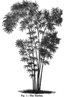
Bamboo as seen in the
Institute Laboratory ... .. . Drawing of Form - Blueprint... ... ...
Wire Machine, used for testing
Tension of Bamboo ... ... ... ...
Shear Block, used for testing the
Longitu-dinal Shear of Bamboo.
Photo and Drawing -. --. ... ...
Emery Machine, 300,000 pounds capacity Bamboo Coluim Split under compression
Drawing of 5-1/2 inch Extensometer,
used in Column Test ... ... ... ...
Bamboo Cracks at a Joint *.. ... ...
Bamboo Trestles and Bridges... ... . Butt of Bamboo, whole and split
Bamboo Grove in China ... Bamboo Grove in China
another view ... ... ... Page Frontispiece. .0 9 .9.. 9... .9.. .9.. ... 9 ... .0 . After Appendix " "
31
58 62 65 6575
89II
II V V Y111 " II.m
I
Y
V
/
/1
I
--C0000**
CONCRETE REINFORCED WITH BAMBOO.
The high tensile strength of bamboo led the
author to conceive the idea of applying this material to the reinforcing of concrete beams on its tension
side. The abundance of growth of the wood and the
ease with which it can be procured in the land of China
would render it of practical value, should it prove to
contribute to the strength of the member to which the
reinforcement of the bamboo has been applied. There
are several large cement factories in China that
pro-duce first grade cement at comparatively low cost. Although reinforced concrete has been used in China
only to a limited extent, time will come when the wave of concrete construction in the West will spread far and wide in the East.
For structures for which steel reinforcing will be too expensive, and where bamboo can do as well
as steel, bamboo can displace steel. For instance,
bungalows, cottages, watertanks, culvert pipes, foot bridges, etc., can be reinforced with this material.
Preliminary Calculation.
zt
Test specimens of reinforced concrete beams are habitually of the dimensions 40 X 8' X 6' - 8".The beam is to be tested with a six feet span, loaded
by two loads symmetrically placed at one third of the
span from each end. Consequently the calculation
should be made on this assumed beam.
The Joint Committee recommends " The lateral spacing of parallel bars should not be less than two
and one-half diameters, center to center, nor should the distance from the side of the beam to the center
of the nearest bar be less than two diameters."
This practically fixes the design of the section as shown in the following figure.
3
There remains, however, the calculation of maxi-mum loads which may be expected of the beams to bear
with such reinforcement. To do so, the common form-las for reinforced concrete has been used. From the long list of formilas numbering sixteen, the one of immediate application to this case is the. following:
3 r+2n X = 1/6 bd2 Cn
---(r + n) 2
where X = bending moment due to safe loads.
b
=breadth
ofbeam.
d = distance from center of tensile steel area to compression side of beam, or the
effec-tive depth.
C = compressive stress in the concrete.
4
n = ratio of Modulus of Elasticity of steel to
that of concrete.
r = ratio of tensile stress of steel to compres-sive stress of concrete.
In this case,
b
= 4"; d = 7"; C =650concrete); n = 15; r = 15.
(1 : 2 : 4 (The values of C, n and r, are Joint Committee reconzrendations . )
2 3 X 15 + 2 X 15
*M 1/6 X 4 X 7 X 650 X 15
---(15 + 15 )2
=
26,600 inchlbs.
...(1)
The weight of concrete beam is:41/12 X
/12
X 6.66 X 150 (lbs, per cu.ft.) = 220# 22277t. per
foot
=
--- = 33.4666
4//ft.
The maximum bending moments due to safe W
load --- and its own weight is: 2)
W 2
220 X 61 3 Equat ing ( 1 ) and (2 ) we have
W 220 X 6
M
26,600 = --- X 2 X 12 +--- X 122 8
W = 2050#
W being the load which is expected of this beam to --- X 2' + - - - - .. . . . .. (2)
S
s tand without failure. As will be seen later, the maximum load under which the beams fail is many times
the above figure. This shows that in the design a good factor of safety has been used.
There remains, however, the calculation of stirrup near the ends of support, in order that the
beams will not fail by diagonal shear, and the
ten-sion in the reinforcing rods may be fully developed.
The Joint Committee recommends a working -shearing stress of 40 lbs. per sq. in.
V = V b
where V = total shear that the concrete is capable to bear without the help of stirrups.
v
= allowable shear stress = 40#/.'j = vertical distance between points of
appli-cation of horizontal tensile and compres-sive stresses.
3 r + 2 n But = d ---3(r + n) 3 A 15 + 2 X 15 =7 X --- -- 5.83" 3(15 + 15) Therefore V = 40 X 4 X 5.83 933#
There is at the support a shear of 1025#+ 110# = 1135#.
Then 1135 - 933 = 200# must
be
taken upby
stirrups.The proportion
1135 : 200 = 2' : x
will give the distance from support within which rein-forcement by stirrups is necessary. Solving the equa-tion,
x
=
.35'
= 4.2"In the actual beam, the stirrup reinforcement extends as far as 20" from the ends of support to make it
doub-ly sure failure will not occur at sections other than
that of maximum bending moment. For stirrups 1/8"
rods are used.
The calculation for beams reinforced with
bamboo Strips are identical with that for steel in
however
7every respect, with the difference that since bamboo is approximately 2/3 of the tensile strength of steel (from Ulrich's test), the sectional area of bamboo should be 3/2 times as much as that of steel; and the beams reinforced with bamboo are so designed.
The author is aware of the unsoundness of this
assump-tion; but in the absence of better information on this
subject, this assumption is perhaps as good as any other. The ratio of sectional areas for steel and bamboo can be revised should the tests prove that the assumption is incorrect.
The bamboo strips available are of the
sec-tion
.3" X .7"
=.21
. Three strips are usedfor one beam. Hence
3 X
.21
=63
Steel with cross-sectional area of 2/3 of bamboo should
be as strong as the latter according to the assumption
2/3
X
.63 = 42LTwo 1/2" rods are used.
Area = 2 X
.19637
=.3926
.3926
Actual ratio = --- -
.623
.63
The following figure shows the beam in its final form. It should be noted that two small steel rods of 1/8"
8
diameter are put near the top of every beam, the idea
being to prevent possible collapse due to making the top side the tension side when handling.
Design of Form.
The accompanying blueprint shows the forms used for the making of these beams. The sides and
bottom are the same, but end pieces are different for different beams, as indicated, to make provision for the ends of the reinforcing rods to lodge in. As
actually constructed, every joint is a mortise and tenon joint, and with numerous wood screws, every joint is made watertight.
We must note here that by keeping the lower edges of both steel and bamboo pieces at an equal dis-tance from bottom of beams, the value of d for steel in the preliminary calculation is not strictly correct
for bamboo; but the discrepancy is small and can be
neglected. Perhaps the assumption of ratio of cross sectional areas for steel and for bamboo takes care of this discrepancy.
Four beams, two of which reinforced with bamboo, and the remainder with steel, have to be made.
Two extra bottoms are made to make possible the pour-two
ing of concrete two weeks after the first/are
finish-ed, using the same sides and end pieces, inasmuch as
it is unsafe to remove the bottom in such a short pe-riod of time.
/A V7&
43x~
HJ;>-
1 fvf 9 f">P JO 37 7
'a0
/A
OupE
Estimate of Material Required.
4 steel rods: 1/2" dia. 6'-11" each.
Length of one stirrup = 15.5"
4 beams each with 14 stirrups.
Total volume = Cement = 1/7 Sand = 2/7
It
of gravel as
voids in the
sieve.
x
x
Total 27'- 8" " 55'- 4" Total 72.5"1
:2:4 concrete.4x8
8" 8" --- X 6.66) X 4 + 6 XX--x
X--144 12 12 12 7.67 cu. ft.7.67
=1.09
cu. ft. 7.67 = 2.2 cu. ft.is customary to have as many cubic feet
concrete, cement and sand filling up
gravel. Gravel to pass through 1/2"
Bending of Stirrups.
To secure uniform results, a form was made of a thick pine plank 10" X 24" X 1-1/2" into which were driven from behind spike nails about 3" long at carefully marked points where the stirrup stopped or
cornered. This insured the greatest degree of
stirrup was only 1/8" diameter, bending with a pair of pliers was not difficult.
The stirrups were fastened to the steel or
bamboo rods by means of small iron wires. 4 such
fastenings on one stirrup for the steel,.and five for
ba0boo.
Pouring of Concrete.
It was on February 26, 1914, that the first
two beams were made. The outside temperature was
in the neighborhood of 320 F., which was, of course,
objectionable as the concrete was liable to freeze
be-fore setting took place. Fortunately the pouring was executed in a shed adjoining the boiler room of the Instit-ite, which kept the temperature inside the shed always above 320 F. The forms having been previously oiled with cylinder oil to prevent
con-crete adhereing on to the form, the concon-crete was mixed according to the directions given in Baker's "Masonry Construction". It was, of course, all hand mixing.
In this pouring, gravel larger than 1/2" grade was used by mistake; when discovered it was
difficult to pack well under and between the
reinforc-ing rods. This difficulty was more pronounced in
the bamboo beam in which three strips were crowded
in-to the space occupied by two steel rods in the steel
beam.
Three 8" cubes were first poured which of course presented no difficulty. But when the beams
were poured, packing the portion underneath the rods was a trying task.
A maximum and minimum thermometer was put
inside the shed to see if the temperature would fall sufficiently to freeze the concrete within a day or
two. The temperature did not fall below 320 F.
with-in several days after the pourwith-ing of the concrete.
Water was occasionally sprinkled over the top of the beams to prevent sudden drying.
Two weeks after the first pouring, the con-crete had set sufriciently to permit the removal of the sides and ends of the wooden forms, leaving the bottoms intact. Extra bottoms were screwed on to
the sides and ends to make ready for the second pour-ing of the other two beams.
The second pouring was performed on March 12, 1914. The process was identically the same as
the previous; but the difficulty of packing was much less than before, inasmuch as 1/20 gravel was used in place of the larger size.
Test of Beams.
60 days was the age chosen at which these
beams and cubes were to be tested. The test on the first two beams and three cubes was performed on April
17, 1914, in the Beam Machine in the basement of the Applied Mechanics Laboratory of the Institute. The
cubes, previously faced with plaster of Paris to give a good bearing, were tested for compression in the
Emery Machine of 300,000# capacity in the same base-ment. They gave the following results:
Compressive Strength of 8" Cubes.
Concrete 1:2:4; age 60 days; stored gravel l".
in air.
No. of Specimen. Max. Load. Comp.Stress,lbs./sq.in.
1 129,000# 2020
2 132,000# 2060
3
130,0
00#
2030Average 2040
Beams were then tested in the Beam Machine. The beams were placed on jack screws 6' apart from center
to center with an overhang of 4" at each end. Be-tween the beam and jack screws were placed steel
plates to distribute pressure. The load was a sin-gle load concentrated at the middle, and was applied
by raising the jack screws, first one end then the
other, This load was balanced by a weight or
weights through a system of levers. The
deflec-tion was measured by micrometers on both sides of the beam, with reference to two piano wires, one on each
side, stretched taut by weights at each end at the mid-dle height of the beam. Loads increased at 500 lbs. intervals. The following pages show the result of tests on the first two concrete beams.
- Transverse Test
-April 17, 1914.
Specimen: Concrete beam reinforced with steel rods.
Concrete 1:2:4; l11 gravel; age 60 days, storage
in air. Load R D R D D2 - 2 1 1 2 2 2 500 .066 Sum Remarks. .037 1075 .077 .011 .048 .011 2000 .105 .028 .075 .027 2925 -141 .036 .111 .036 4000 .189 .048 .159 .048 .011 .028 .036 .048 .011 .039 .075 e Cra1Lc shown at
.123 this load out-side of
stir-nups.
= reading by micrometer No.
"f " " No. 2.
- difference of readings on micrometer No. 1 if if if if V No. 2.
R R2=
1.
Manner of Loading. Span
D imens ions
Weight of yore
* beam Max. scale reading
IG
Single concentrated load at middle.
6'
25 lbs. 220 lbs. 4400 lbs.
- Transverse Test
-1
April 17, 1914.
Specimen: Concrete beam reinforced with bamboo.
concrete: 1:2:4; gravel 1"; age 60 days; storage
in air. R2 D2 - 2 2 .211 .263 .325
.372
.482 crack cement. Sun Remarks. .052 .061 Small crack .062 .061 .122 4 small cra evenly spa .047 .049 .171 .110 .111 .282at a bad spot patched with neat
cks ced. Load R 600
875
1100 1300 1600 3120 .294 .363 . 423 . 474 .585 .069 .060 .051 .111 Bad18
Manner of Loading: Single concentrated load at middle.
Span 6'
Dimens ions 46I 8*
Weight of yore 25 lbs.
* beam 220 lbs.
Max, scale a"4 reading 3120 lbs.
S5TRES53 3TRAIN
DIAGRAM
re-3T I
The test for the second set of beams and
cubes was performed on May 7, 1914. at the same place. The procedure and operation were practically the same
as in the former tests. The manner of loading the
beams was two concentrated loads dividing the span
in-to three equal parts.
The three cubes gave the following results: Compressive Strength
Concrete 1:2:4; age 60 days;
No.of Specimen. Max. Load
in lbs. 1 142,200 2 141,500
3
118,300
of 8" Cubes. storage gravel 1/2" in air; Comp. stress in Lbs./sq. in. 2220 2210 Average 2220The following pages show the results of
- Transverse Test
2
-May 7, 1914.
specimen: Concrete beam reinforced with steel rods. Concrete: 1:2:4; gravel 1/2"; age 60
D 1+ D 2 DI R2 D2 ~~2--w
.063
.005 .069 .007 -080 .011 .093 .013 .105 .014 .121 .014 .137 .015 -151 .016 .166 .014 .185 .015 .204 .026 .231 .020 .250 .006 .029 .013 .012 .016 .016 .014 .015 .019 .019 .027 .019 .005 .012 .012 .015 .015 .015 *016 -017 .017 .026 .020 Sum .012 .024.039
*
054
.069 .085 -102 .119.145
.165 days; storage in air. Remarks. 2 cracks, one 10 to the right and other 4" to the left of C. L.Manner of Loading: 2 concentrated loads dividing the span into 3 parts.
Span 6'
Dimensions
Wt. of yoke, I-beam, etc.
1" beam
Max. scale reading
Sketch: Load R 500 1000 1500 2000 2500 3000 3500 4000
4500
5000 5500 6100 6500 -015 .020 .027 .038 -051.065
-079
.094 - 110 .124.139
.165 -185 220# 2 20#6900#
- Transverse Test2
May 7, 1914.
Specimen:
Concrete beam reinforced with bamboo.
Concrete: 1:2:4; gravel 1/20; Load R1 D R 2 2 2 2 2
500
1100
1500
2000 25003000
3500
4000
.216 .285.359
.453
.558
.668 -884*069
.074
.094
.105 .110.216
.009
.074
.159 .258 .366 .573 .743.065
.085-099
.108
.207
.070.090
.-102.109
.214age 60 days; storage in air. Sum
.160
.262.371
.585
Remarks. Cracks at pts. of application of loads and at middleManner of loading: 2 concentrated loads equally spaced.
Span
6'
Dimens ions
4H 18'
Wt. of yoke, I-Beam, etc beam
Max. s cale reading Sketc24:
220# 220#
-3TIR
E5
MTIAIN
DlAG C
TE TMAN N E:40F LOfl N G
7.
4
pp
N) CA)
Notes on the Tests.
Beams reinforced with steel did not show cracks at low loads but at high loads, cracks began
to develop. At maximum load, deflection was
con-siderable and beam failed to pick up load. On the
other hand, the beam reinforced with bamboo began to
crack at very low loads; crack continued to develop as the load was added but the beam picked up load readily in spite of the hideous outside appearance of the beam. The explanation of this phenomenon will
be attempted when we come to the "Analysis of Result"
on page .
It was feared thatencased in concrete,
bamboo would rot, from causes for being either too
wet or too dry. Accordingly one of the failed
beams reinforced with bamboo was knocked open, and
strips were taken out and tested. Care was taken
that the hammering did not strain these strips. The result of test showed:
Strips of Bamboo Encased in Concrete 60 days. Previously stressed by testing.
No. Section Breaking Load. Tens. Lbs./sq.in,
1 0.293"X 0.260" 1600 lbs. 21,000
2 0.300"X 0.264" 1600 lbs. 20,200 3 0.273"X 0.225" 1400 lbs. 22,750
Average 21,320
Comment on this result will be found in "Analysis of Results" on page 2r.
The strips showed perfect freshness when
taken out from the concrete. The bonding between
concrete and bamboo seemed to be perfect in every way. Stirrups did their share well as was shown by the
breaks which in every beam occurred outside of the
limit of the stirrup reinforcement.
In the test of the second two beams, it was
observed that beams failed at sections close or under the roller which transmitted half of the total load. If there were any explanation at all, it could be at-tributed to the excessive localized stress due to the
point of contact of the roller and beam. Should
this be the cause, it could be remedied by interposing a narrow steel plate between the roller and the
Analysis of Results.
It is necessary that the results be analyzed,
and conclusion, if there can be any, be drawn as to the actual values of these investigations.
1. The compressive strength of the plain con-crete cutes agrees in remarkable closeness with that
of others tested in the Institute Cement Laboratory.
Thus, in 1905, a series of compression tests was made
on concrete blocks of same mixture, age and storage, giving results of 2070 #/V". On page the
av-erage of three cubes was 2040#43", while on page
202'0#/o" average. Smaller gravel, and therefore
better uniformity of mixture accounts for the increase
of strength of the last three cubes.
Since the working compressive stress was taken at 650#In", we have a factor of safety of
2040 1st. set of tests --- = 3.14 650 2220 2nd. set of tests --- = 3.41 650
which are ample for the compression side under steady
load. The character of cracks showed that the com-pression side was never stressed to its limit.
2. The Mayi.mim Load. (a) The first test. It is to be recalled that in the preliminary
calcula-tion the loading was of two concentrated loads equally spaced, while the actual load in the test was of a sin-gle load concentrated at the middle of the span. It
is, therefore, necessary to make the correction
in
or-der that the. theoretical load and actual load can be
compared. On page
4
we have tie resistingmo-ment of the material:
M = 26,600 in.lbs.
and the bending moment for a load concentrated at mid-dle
W 220 X 6'
= --- X 3'
+---2 8
They should be equal
W 220 X 6 26,600
--- X 3 +- --- =---= 2216
2 8 12
W= 1365 lbos.
The actual maxinua load, however, was:
Steel bean 4400 lbs.
Bamboo " 3120 lbs.
For steel team we have a factor of safety of
4400
--- = 3.2
For bamboo beam we have a
factor of safety of
3120
---
=
2.3
1365
The ratio of maximum loads, steel to bamboo is:
4400
--- = 1.1
3120
That is, the assumption in the preliminary calculation that for the two beams to stand equal loads, the areas of reinforcing rods should be inversely proportional to their fibre stress. For example, if the tensile
strength of bamboo is 2/3 that of steel, the
reinforc-ing area of bamboo should be 3/2 that of steel. Now
if we would increase the area of bamboo to the amount
of
3/2 X 1.41' = 2.12,
we should expect the bamboo beam to stand as much load as did the steel beam.
The discrepancy appeared to arise from the wrong value used of the tensile strength of bamboo.
When the beam was designed, the only available
infor-mation on the strength of bamboo was from the results
of tests made by a German experimenter, Max Ulrich, whose work is reviewed elsewhere in this report, and
the tensile stress was shown to be very nearly 2/3
author showed this stress excessively author's value of tensile strength as erage of eight tests was 18,400 #/t". tensile stress of structural steel to
we have the ratio of
high. The
shown by the
av-Taking the be 60,000#/"
60000
--- =326*
18400
If the bamboo area were proportioned with this ratio,
the bean would have stood as much, if not more, load
as did steel. The soundness of the assumption is sustained.
(b ) The second test.
Expected load ... ... 2050#
Actual load, steel ... 6900#
bamboo
... 4600#Factor of safety, steel... 3.37 " " " tamboo ... 2.25
Max. Load of Steel
---Max. Load of Bamboo
6900
4600
1.5
If the area of bamboo were increased to
3/2
X 1.5 = 2.25we would expect the bamboo beam to stand as much load
30
above, is 3 inasmuch as the tensile strength ratioof steel to bamboo is 3.
The remarkable proximity of results of the two tests can be appreciated in the following table.
Test 1. Test 2. Factor of safety for steel ... 3.2
3.37
" " bamboo ...
2.3
2.3Corrective ratio:
Max. load of steel beam
--- . 1.4 1.5
Max. load of bamboo beam Equal strength area ratio:
Area of bamboo
--- ... ...
2.12
2.25
Area of steel
From plots of the two tests, it can be seen that each additional load produced considerably more deflection on the bamboo beam than on the steel beam.
This can be attributed to the small modulus of
elas-ticity of bamboo. It also explains why cracks in
bamboo beams developed at comparatively low loads. There seemed no way to remedy this except by putting in more reinforcing bamboo strips which is practicable when we remember that the material can be procured in superabundance and at low cost. The author is of
the opinion that if the "equal-strength-area-ratio" be made equal to the strength ratio between steel and
bamboo, the cracks will not develop at such low loads.
Conclusion.
It appears from the tests that bamboo does
contribute to the strength of the beam to which the
reinforcement has been applied, and such reinforcement is practicable both from considerations of durability and strength. The concordance of results of the
tests showed that the bamboo in concrete behaves very
much like steel and can be depended upon to act as we
expect it. There can be no doubt that for small structures bamboo reinforced concrete can be used to advantage.
Much more experimental data is needed to guide the designer. In the absence of any better information, the author recommends the following method of design:
Design the beam as if it were reinforced with steel. Multiply the reinforcing area of steel thus obtained by the ratio of the tensile stress of
product will be the reinforcing area for bamboo.
--- -4~~ ~ 1 -________________ ~~1 I, -z A aib i
4
0 1 4 a 4 1 0 . . 0 .- Tests on the Tensile Strength of Bamboo
-The difficulty of testing the tensile strength of wood in general was so well known that the author
proceeded with every care. The difficulty, of course,
lay in the clamping of ends of specimens such that the specimen should fail by tension and not by shear.
Wood, in general, is strong in tension but very weak
in shear. The fact that bamboo is a species of wood put it on the same ground of suspicion that
ten-sion specimens of bamboo would fail by shear and not
by tension.
A method of preparing the tension specimen such
that the full tension could be developed was proposed
by Mr. Gescher*, under the direction of Professor
Schramb. His specimen consisted of a narrow and
thin strip of hard wood, necked down to about
one-half of the width in the middle for one-one-half of its length, to the ends of which were glued extra strips
of the same kind of wood cross-pieced with wooden
dow-els set in with glue. It did not, however, come out
as expected. Some of them broke by shear at the
neck; others failed through tearing the holes into
.34
which the dowel pins were inserted.
The ease with which bamboo could be bent
naturally suggested a way by which the ends of the
specimen could be secured in the testing machine and tensile strength determined. Accordingly specimens about 8' long were prepared with loops at ends, strap-pei together by wires. The loops were made by steam-ing the ends of the bamboo strips in a steamsteam-ing vessel
of the following construction:
After steaming for an hour, the strips were talcen out and the ends were bent around the outside of
end was finished, the other end was steamed and the process repeated. In this way bends or loops of 4"
diameter could be easily made. The author attempt-ed to bend the ends of strips cold and dry. The smallest diameter obtainable in this way was about 8". Moistened by immersion in water smaller diameters
could be obtained.
The specimen was then put into the Rope Testing Machine of the Institute, the loop ends being held by the pins in the Jaws. The aurvatures of the
loop and pin were so different that extra wooden pieces
conforming to both curvatures had to be interposed
be-tween them. Load was then applied. To our sur-prise, the extension bar clamped on the specimen for a
gauge length of 3' , did not register any elongation as the load was increased. Upon investigation it was found that the wires that strapped the loop ends were giving way under load, and there was considerable
bend-ing at the place where the curve of loop began.
Fur-ther pulling failed the specimen at that place under
light load. It was clearly a case of bending
in-stead of direct tension. It was concluded that this manner of testing should be abandoned.
the jaws of a Wire Testing Machine in the Institute. It met with considerable success. The grip by the
rough cieckered faces of the jaws was so perfect that the specimen broke in two by actual tension.
Encour-aged by this success, a large number of specimens were
made. They were about 4' long, 1/2" wide, necked
down to 1/4" for a length of 3', leaving the gripping ends eaci about 6" long. A gauge length of 30" was
chosen, and elongations measured. In every case the grip was perfect. The jaws of the machine were so designed that the harder the pull the firmer the grip, The ends of the specimen were actually compressed to form a nick which contributed direct resistance to
pull. As will be seen in the following pages, the
in-side fibres, the sap wood, of the specimens in most
cases gave way first, followed by the inner fibres then the outside, the green skin. The tests made by ul-rich showed that the strengths of the t1hree-eeen-, in-side, 4AR44 and outside fibres, varied in the ratio of 1 'r-k4, : 2.25. When the full thickness was tested ,
we naturally expected the inside fibres to give first; and it actually did.
The long gauge length chosen necessarily in-cluded one or two joints. The specimens in almost
all cases failed at one of these joints. The con-Weak
clusion suggested itself that they were the spots in the bamboo.
Tests 1 and 2 were made upon specimens badly
weathered. The curves seemed to have comparatively
more curvature than the others.
Tests 3, 4, 5 were made upon specimens
sea-soned four months. They showed better uniformity of results.
Test 6 was made upon a specimen of short
gauge length such that no joint was included in the length. This was done in order to ascertain
wheth-er or not the joint was a weak spot and responsible
for the failures of the other specimens. The
spec-imen, however, did not show any appreciable increase
in strength.
The seventh test was made upon a specimen
which had for a year been immersed in dirty water in
the pumping well under the floor of the Pierce
Labora-tory of the Institute. The specimen was so soaked
with water that when strained under tension the water
was squeezed out and trickled down the specimen.
The curve presents the same general appearance as
B8 which was in all probability due to a local weakness
near the joint rather than the general decay caused
by the immersion in dirty water.
From these tests it is justifiable in
con-cluding that the weather quality of bamboo is good.
With the exception of one or two, the curves are very flat, and for all practical purposes they can be assumed to be straight. The curvature would be scarcely appreciable, had the scale for the elongation been made half as large. The assumption that the
curves are straight carries with it the inevitable con-clusion that the stress is proportional to strain, and any point on the curve can be used for figuring the modulus of elasticity. In the following table the Modulus of Elasticity is figured by using a point mid-way between the zero load and maximum load.
The caaracteristic points of steel curves, namely, the Elastic Limit, the Apparent Elastic Limit, the Yield Point, are absent in bamboo curve, since the
absence of such points is common to all woods, and
bam-boo is one kind of wood. If we should assume that the Elastic Limit coincides with the breaking point, then the former should be figured on the basis of the latter. The Elastic Limit in the following table is figured in this way.
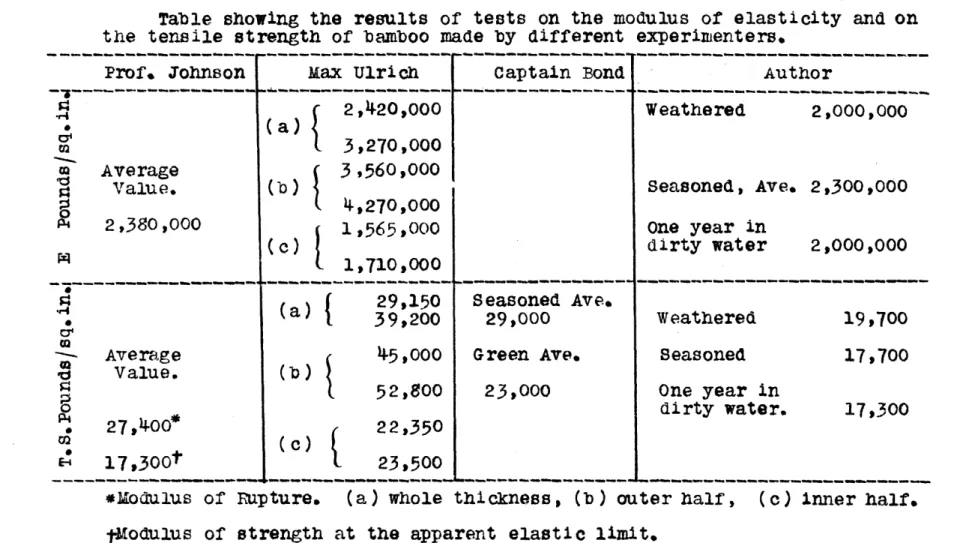
Table showing the results of tests on the modulus of elasticity and on the tensile strength of bamboo made by different experimenters.
Prof. Johnson Max Ulrich Captain Bond Author
---
---f
2,420,000 Weathered 2,000,0000 (a)
3,270,000
m Average 3,560,000
V Value. (b) Seasoned , Ave. 2,300 ,000
4,270,000 2,380,000 1,565,000 one year in (c) 19 ,000 dirty water 2,000,000 --- ---~---
----{
29,150 Seasoned Ave. -r4(a)
( a 39,200 29,000 Weathered 19,700Average 45,000 Green Ave. Seasoned 17,700
Value. (b) 52,800 23,000 One year in 0 dirty water. 17,300 . 27,400* 22,350 (c) 17,300t
-
23,500 - of u . (a---- ---- ne , (----*Modulus of Ruipture, (a) whole thickness, (b) outer half , (c) inner half,
40 From the table it is readily seen that the author's results are lower than those obtained by the other experimenters. The discrepancy seems to arise from the following possible causes:
(a) Difference in the kind of bamboo each
experi-menter used, as there are no less than 200
va-rieties of bamboo.
(b) Difference in the way of preparing the
speci-mens.
Captain Bond's specimens "were
cut
to
shape similar to cement
briquette
---- ", whileMax Ulrich's specimens, as seen from the
pho-tograph, had unusually small reduced sections,
and gauge lengths did not include one or two
joints. Our knowledge of the results of
tests on steel shows us that a briquetted
spec-imen always gives high values. In Ulrich's
specimen, a slight inaccuracy in measuring the cross-section will throw a large error upon
the final result.
The author's tension specimens were about 40" long, having a gauge length of 30" which included one or two joints, and a
uniform reduced cross-section of about
length of the specimen. A larger cross
see-tional area, a longer gauge length and there--fore less uniformity, accounts for the low values the author obtained.
The author claims that his results are
more representative and approach more nearly
the actual working conditions than the rest.
Captain Bond must have been handicapped by
the lack of facility for testing in the field. His results are subject to question. The
ab-sence of joints within the guage length in Max Ulrich's specimen is a serious defect which can not be slighted.
Tension Test No. 1. April 6, Spe cimen: L R 100 .0320 200 .0545 300 .0763 400 .0965 500 1214 600 .1413 700 .1652 800 .1882 900 .2116 1000 .2376 1100 .2602 1200 .2902 1300 .3194 L
=
Load in D *0240 .0225 .0218 .0202 .0249 .0200 .0239 .0230 .0234 .0260 .0226 .0307 .0285 lbs. Bamboo weathered. S Remarks. .0465 .0683 .0885 .1134 .1334.1573
.1803 .2137 .2397 .2623 .2930 .3215 Grip perfect.Broke near joint. Inner fibres gave
way first.
R = Micro-meter Rdgs. D = Diff. of Rdgs. S
=
Sums.Gauge length inches
Dimensions of cross section, inches Max. load on machine, lbs.
Area of cross-section, sq. ins. ...
Elastic Limit, Lbs./sq.in. . . . .
30 .247"X.296 1400 .073 19,200 Modulus of Elasticity ...
1,710,000
47 1914.BAMo 50 1N TE- .) iN
I.- T i5-T
N A NP9I A
GR
\M
6A M CTE- LE N RT H :10,
S AD L-f VE AT HE RE.D
7400
Tension Test To. 2.
April 6, 1914.
Sp e c imen: Bamboo weathered.
Remarks.
Grip perfect. Broke near joint.
Inner fibres gave
way first.
L = Load in lbs.
D = Diff. of Rdgs.
R = Micrometer Rdgs. S = Sums.
Gauge length, inches
Dimensions of cross-section, inches ...
Max. load on machine, pounds
30
.264X.281
1500
Area of cross-section, sq. inches ... Elastic Limit, Lbs./sq.in.
.0742 20,200 Modulus of Elasticity ... 2,190,000 44 R L 100 200 300
400o
500 600 700 800 900 1000 1100 1200 1300 1400 .0250.0435
.0607 .0792 .0983 .1142 .1380 .1578 .1784 * 1990 .2200 .2398 .2600 .2838 S.0357
.0542.0733
.0892 .1120 .1318 .1524 .1730 .1940 .2138 *2340 .2578 .0185 .0172 .0185 .0191 .0159 .0238 .0198 .0206 .0206 *0210 .0198 .0202 .023813A M130 0 1N T E Ni 0 N 60 GA U GE L E- N1 T H 0" DA DLY NEA T H E E D 5004 400 6 00 koo Loo
Tension Test No. 3.
April 9, 1914. Specimen: Bamboo, seasoned 4 months.
Remarks.
Grip perfect.
Broke near joint. Inner ribres gave
way first.
L = Load in lbs. D
=
Diff. of Rdgs.R = Micrometer Rdgs. S
=Sms.
Gauge length, in inches
Dimensions of cross-sections, inches ....
Max. load on machine, lbs. ...
Area of cross-section, sq.in. ...
Elastic Limit, Lbs./sq.in. ...
30
.413*I. 303
1980 .1255 15,800 Modulus ofElasticity
... 2,130,000 R S L 100 200 300 400 500 600 700 800 900 1000 1100 1200 13001400
1500 1600 1700 -. 0015 .0095 .0213 .0328 .0453 .0556 .0701 .0824 .0941 .1052 .1200 .1317 .1430 .1556 -1692 .1807 .1949 .0110 .0118 .0115 .0125 .0103 .0145 .0123 .0117 .0111 .0148 .0117 .0113 .0126 .0136 .0115 .0142 .0228 -0343 .0468 .0571 .0716 .0839 .0956 .1067 .1215 .1332 .1445 .1571 .1707 .1822 .1964-~~~~~ - -. i - - . .
-If . . . . . . . .-- ---
-~~~~~~~~... .... . .- - -- - -- t **
--1 . .. .
48 Tension Test No. 4.
April 9, 1914.
Specimen: Bamboo, seasoned 4 months.
R D S Remarks. .0000 .0111 .0111 .0229 .0118 .0229 .0353 -0124 .0353 .0478 .0125 .0478 .0601 .0123 .0601 .0736 .0135 .0736 .0858 .0122 .0858 .0982 .0124 .0982 .1108 .0126 .1108 .1242 .0134 .1242 .1360 .0118 .1360 Grip perfect.
.1478 .0118 .1478 Broke between joints.
.1608 .0130 .1608 Inner fibres gave
.1741 .0133 .1741 way first. .1874 .0133 .1874 L = Load in lbs. D = Difference of Rdg R = Micrometer Rdgs. 's. S = sums.
Gauge length, inches
Dimension of cross section, inches
Max. load on machine, ts. ...
Area of cross-section, sq.in. ...
Elastic Limit, lbs./sq.in. ...
Modulus of Elasticity ... 30 .376 X .302
1950
.1135 17,100 2,310,000 L 100 200 3004oo
500 600 700 800 900 1000 1100 1200 1300 1400 1500 1600TIO 0
Albo
BAM W N TE. 14 5 10 KTK E YU
MAGMA
GA u Gr F- LF- Iq CtT-H m9 00 A '3 N E. D T VI Z oo-': ... . 71 0.0.100
Tension Test No.
50
5.
April 9, 1914.
specimen: Bamboo seasoned 4 months.
D .0118 .0122 .0121 .0125 .0135 .0129 .0129 .0131 .0131 .0125 .0130 .0139 .0126 .0139 .0146 S Remarks. .0230 .0351 .0476 .0611 .0740 .0869 .1000 .1131 .1256 .1386 .1525 .1651 .1790 .1930
Broke near the joint,
L = Load in lbs.
D = Difft. of Rdgs.
R = Micrometer Rdge.
S = Sums.
Gauge lengthinches
Dimensions of cross-sections, inches.. Max. load in lbs.
Area of cross-section, sq. in. ...
30
.381"X.285
1990
.1086 Elastic Limit, lbs./sq.in. ...
Modulus of Elasticity... L 100 200 300 400 500 600 700 800 900 1000 1100 1200 1300 1400 1500 1600 R .60000 .0118 .0240 .0361 .0486 .0621 .0750 .0879 .1010 .1141 .1266 .1396
.1535
.1661 .1800 .1946 18,350 2,375,000IA GOONT NO
9
00 U (4E L, N TH o30 NEb 4 MMTRS
Tension Test No. 6. April 27, Specimen: R D .0035 .0041 .0040 .0046 .0043 .0036 .0046 .0034 .0044 .0070 .0056 S .0076 .0116 .0162 -0205 .0241 .0287 .0321 .0365 .0435 .0491 Bamboo Remarks. No joint within gauge length. L = Load in lbs. R = Micrometer Rdgs. D = Mean of diff. of Rdgs. S
=
Sums.Gauge length, inches 8
Dimensions of cross-section, inches
Max. load in lbs.
Area of cross-section, sq. i. ...
Elastic Limit, lbs./sq.in. Modulus of Elasticity .3168 X .2900 .0917 19,600 2,380,000 L 1914. 100 200 300 400 500 600 700 800 900 1000 1200 14.00
loo
i0o
1000
BAMB60 MTEMSIONTRE53-, TMI N D AG R P M
Soo
G.4 44r E L ENC-4TH110JOIJ-41- WITHIN THF- LE-N -TIA
70o Soo -100 Zoo 400 .01 0 -z .04- 0
54
Tension Test No. 7.Spe cinen: Bamboo,1 yr.
May 14, in dirty water. Remarks. L = Load in lbs. D = Diff. of Rdgs. Gauge length, R = Micrometer Rdgs. S = Sums. inches Dimensions of cross-section, 30 inches *
Max. load on machine, lbs.
Area of cross-section, sq.in. ...
Elastic Limit, lbs./sq.in.
Modulus of Elasticity 2... S 1914. L 100 300 500 700 900 1100 1300 R .0265 .0685 .1150 .1690 .2150 .2640 .3150 D .0420 *0465 040 .0490 .0510 .0885 .1425 -1885 .2375 .2885 .236 X .317 1300 .0746 19,300 .. 2,o000,000
A
B 500 IN TE 14 616 11
TRE-3 -5TRAI N DIA( WAM
A lJCjE LF-NCiTH 30"ON E YEAR IN DIRTY WATE R
__Solo
ro
OD
Tests on Shearing Strength of Bamboo.
Wood is as a rule very weak in longitudinal shearing strength, and bamboo, being a species of wood, is no exception to the rule. Many tension specimens
have failed by shear, and yet how surprising it is to
find so little attention has been paid to it. None of the experimenters who made tests on the strength of
bamboo has given the subject its due consideration.
It is the opinion of the author that in practice
ten-sion members on structures made of bamboo will never
fail by tension but will in all probability fail by shear. For this reason it is worth while to look into the subject rather carefully.
A preliminary test was made upon a section of bamboo so shaped that when placed between the heads of the testing machine and compressed, longitudinal sections would slide by each other. This method
works well for testing shears of timbers where large
blocks of wood can be easily gotten and good footing
obtained. But it failed in the case of bainboo for the reason that good footing could not be obtained,
the footing, thus introducing tension into Stress. Various schemes were tried without good success. Finally, a shearing block was designed by the author
as shown in the accompanying illustration. It
con-sisted of two thick, rectangular steel plates bolted together by four bolts passing through four short pieces of piping which acted as distance pieces
be-tween the steel plates. In the center of each
plate was cut a slot, into which a plunger or punch fitfed accurately, taking care, however, that the
close fit did not entail friction. When in use, a
section of bamboo 2" X 1 was placed between the
plates across the bolts, and clamped in place by screw-ing down the four nuts. Then the punch was put
in-to the slot of the upper plate over the specimen, and the whole placed between the heads of the testing
ma-chine. The scheme was attended with such success
that it was employed in the whole series of shear
tests. It is hardly necessary to add that the
clamping of the specimen prevented the spreading of
the footing.
In the following table are shown the results of two series of tests, one on specimen with joint,
SS
and the other without joint. The column headed with
"Number" gives the distance in inches that each
speci-mien was originally situated from the butt of the cane.
For example, the "number 92" specimen was cut from a section 92" from the butt of the pole. This was
done primarily to study the shearing strength at dif-ferent heights of a bamboo pole, as it is to be remem-bered that the thickness of the pole
varies,diminish-ingly. always, from butt to tip.
Specimens marked with an asterisk had notches
at the shearing sections both at top and bottom. The idea was to study the influence of the specimen upon the shearing strength of the material from which such specimen was made.
- Shearing Strength of Bamboo -Table I. Specimens w-tht Joints. Number (Distance from Butt) Ins. Sectional Area of one Shear-ing Section. Sq. in. Load Shearing Strength. In-lbs. Lbs/sq.in. 1900 1150 1570 1260 1330
1650
1150 Av. value5
72 92 113 138 206 255 .40.34
.38
.35
.33
.37
.32
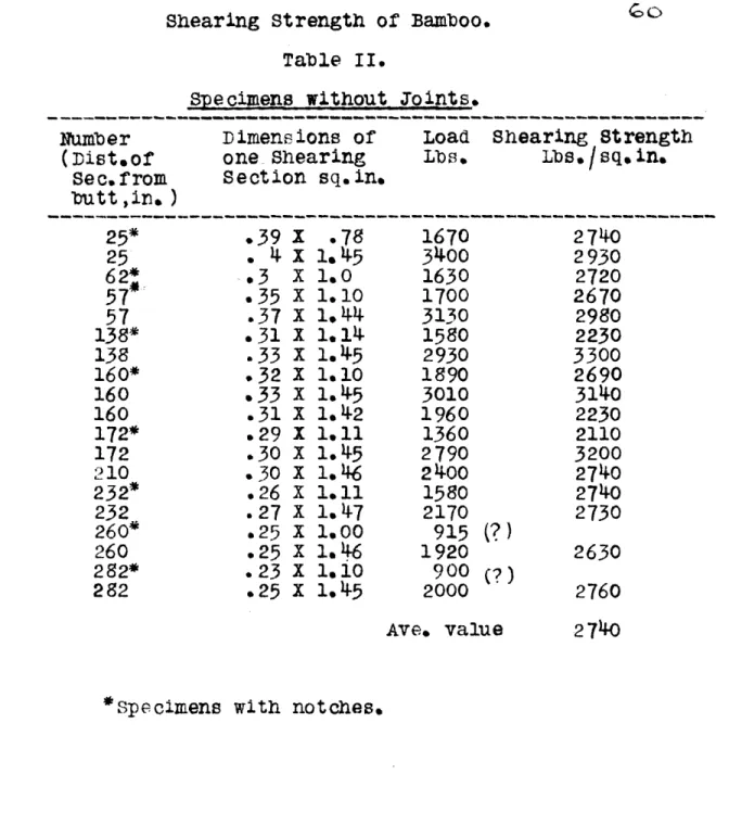
2380 1690 2070 1800 2020 2230 1800 2000Shearing Strength of Bamboo. Table II.
Specimens without Jo ints.
Number (Dist.of Sec.from butt ,in.) Dimensions of one-Shearing Section sq.in.
Load Shearing Strength
Lbs. Lbs./sq.in.
.39
1.
4
x
.3
X
.35 X
.37 X .31 X.33
X .32 X.33
x .31 X .29 X .30 X .30 X .26 X .27 X .25 X .25 X .23 X .25 X .78 1.45 1.0 1.10 1.44 1.141.45
1.10 1.45 1.42 1.11 1.45 1.46 1.11 1.47 1.00 1.46 1.101.4-5
1670 3400 1630 1700 3130 1580 2930 1890 3010 1960 1360 2790 2400 1580 2170 915 1920 900 2000(?)
P)
Ave. value*Specimens with notches.
25* 25 62*
57*
57
138* 138 160* 160 160 172* 172 210 232* 232 260* 260 282* 282 2740 2930 2720 2670 2980 2230 3300 2690 3140 2230 2110 3200 2740 2740 2730 2630 2760 2740It is evident that the joint is a weak spot in
the bamboo inasmuch as the everage for shear for
speci-mens with Joint was 2000#/bW, while without joint
2740#/o. It is also seen that the shearing strengths
of top and bottom pieces from the same cane of bamboo
do not differ in any material way. Notched
speci-mens seem to give lower values than those from plain specimens, by which it is meant that the specimen is
to be out from a section of bamboo in a band saw and
left as it is without being subjected to further
work-irig. The notches in author's specimens were
obtain-ed by cutting the specimen in the band saw, which cut-ting might have injured some of the fibres near the shearing sections and might be responsible for the lower shearing strengths.
In order to appreciate the value of these tests on shear, a simple problem will be solved here. Let
it be required to design a joint in a bamboo structure secured by round hollow iron pins passing through
holes drilled in the members connected, such that a load of 2000# can be transmitted by the joint. The bamboo Is to be of 3-1/2" outside diameter and 1/2"
thick.
(0 z
of bamboo is 8800#/a". Using a factor of safety of
4 we have compressive
strength
= 2200#/fo0. Hence theoutside diameter of the pin
2 (D I 1/2) X 2200 = 2000
D =
.91'
say1".
The inside diameter of the hollow pin may be 3/4.
How we mst determine the length from the pin to the end of the member so as to have sufficient shearing
HLHI
areas to stand the pull or push as the case may be. 500 X 4 X L X 1/'2 2000 L2'
using a factor of safety of 5 for shear of bamboo.
If made shorter than what is required, the shaded por.
Column Tests on Bamboo.
The author at first had an ambitious program for the column tests on Bamboo, but the climate in Boston, where these investigations were conducted delivered a
blow to the whole scheme, for it successfully cracked 80 per cent of twenty to thirty large canes that were
especially ordered from China for these tests. It
was clear that the whole plan must be abandoned. We are glad that Captain Bond and Mr. ilrich made some
column tests, by which the designer can roughly be guided in the absence of better information. The only criticism upon their test is the small size of
specimens used by them. Both of the experimenters made column tests on specimens whose outside diameter
little exceeded one inch, while in actual practice
columns of 4 or 5 inches outside diameter are not un-common. We have reason to believe that results of
tests on small specimens can not apply to large
col-umns. There is need of tests on full size columns.
Some experiments along this line however, were performed before the others cracked. The column had the following dimensions:
Length ..---... '414
Average outside diameter ... 3.34"
Average inside diameter ... 2.76"
Weight . ..---... .