Publisher’s version / Version de l'éditeur:
Vous avez des questions? Nous pouvons vous aider. Pour communiquer directement avec un auteur, consultez la
première page de la revue dans laquelle son article a été publié afin de trouver ses coordonnées. Si vous n’arrivez pas à les repérer, communiquez avec nous à PublicationsArchive-ArchivesPublications@nrc-cnrc.gc.ca.
Questions? Contact the NRC Publications Archive team at
PublicationsArchive-ArchivesPublications@nrc-cnrc.gc.ca. If you wish to email the authors directly, please see the first page of the publication for their contact information.
https://publications-cnrc.canada.ca/fra/droits
L’accès à ce site Web et l’utilisation de son contenu sont assujettis aux conditions présentées dans le site LISEZ CES CONDITIONS ATTENTIVEMENT AVANT D’UTILISER CE SITE WEB.
First Middle East Conference on Smart Monitoring, Assessment and
Rehabilitation of Civil Structures (SMAR 2011): 8 February 2011, Dubai, UAE
[Proceedings], pp. 2-8, 2011-02-08
READ THESE TERMS AND CONDITIONS CAREFULLY BEFORE USING THIS WEBSITE.
https://nrc-publications.canada.ca/eng/copyright
NRC Publications Archive Record / Notice des Archives des publications du CNRC : https://nrc-publications.canada.ca/eng/view/object/?id=ef3ddc86-7a7c-410c-9dd4-750faa43ced2 https://publications-cnrc.canada.ca/fra/voir/objet/?id=ef3ddc86-7a7c-410c-9dd4-750faa43ced2
NRC Publications Archive
Archives des publications du CNRC
This publication could be one of several versions: author’s original, accepted manuscript or the publisher’s version. / La version de cette publication peut être l’une des suivantes : la version prépublication de l’auteur, la version acceptée du manuscrit ou la version de l’éditeur.
Access and use of this website and the material on it are subject to the Terms and Conditions set forth at
Fibre optic sensors for high temperatures and fire scenarios
http://www.nrc-cnrc.gc.ca/irc
Fibre opt ic se nsors for high t e m pe ra t ure s a nd fire sc e na rios
N R C C - 5 3 9 2 1
A d e l z a d e h , M . ; G r e e n , M . F . ; K h a l i f a , T . ; L i ,
W e n h a i ; B a o , X . ; B é n i c h o u , N .
A p r i l 2 0 1 1
A version of this document is published in / Une version de ce document se trouve dans:
First Middle East Conference on Smart Monitoring, Assessment and
Rehabilitation of Civil Structures (SMAR 2011), Dubai, UAE, February 8-10,
2011, pp. 1-9
The material in this document is covered by the provisions of the Copyright Act, by Canadian laws, policies, regulations and international agreements. Such provisions serve to identify the information source and, in specific instances, to prohibit reproduction of materials without written permission. For more information visit http://laws.justice.gc.ca/en/showtdm/cs/C-42
Les renseignements dans ce document sont protégés par la Loi sur le droit d'auteur, par les lois, les politiques et les règlements du Canada et des accords internationaux. Ces dispositions permettent d'identifier la source de l'information et, dans certains cas, d'interdire la copie de documents sans permission écrite. Pour obtenir de plus amples renseignements : http://lois.justice.gc.ca/fr/showtdm/cs/C-42
-.1.-
Abstract of Paper No: 252
Fibre optic sensors for high temperatures and
fire scenarios
Masoud Adelzadeh, Mark F. Green,
Tarek Khalifa
Queen’s University, Kingston, Canada
Wenhai Li, Xiaoyi Bao
University of Ottawa, Ottawa, Canada
Noureddine Bénichou
National Research Council,Ottawa, Canada
In both industrial applications and fire scenarios, sensing may be required at very
high temperatures. Such sensing could be used to monitor and control equipment in
industrial situations or to provide an emergency management system in a structural
fire. Conventional fibre optic sensors (FOS), however, are limited to relatively low
temperatures. Thus, this paper discusses the development of technology for fibre
optic sensing at high temperatures.
FOS with a special coating for resisting high temperatures is being employed to
measure temperatures and strains on fibre reinforced polymer (FRP) tensile coupons.
These sensors are attached to the coupons and tested in a special high temperature
material testing facility at Queen’s University. This test facility can perform
well-controlled tests up to 600°C with a load capacity of 600 kN. The stimulated
Brillioun scattering method (SBS) is used to interpret the measurements. Using
Optical Frequency Domain Reflectometry (OFDR) on data collected from carbon
coated fibres, a relationship between strains and the optical wavelength shifts is
discovered. In addition to FOS, the particle image velocimetry (PIV) method is used
to determine the state of strain and deformation in the coupons.
To illustrate the potential application in a structure, two full-scale T-beams (4 m
span) are constructed with FOS attached to the internal longitudinal reinforcement.
These T-beams are strengthened with external FRP, and fire protection for the FRP
is provided by sprayed insulation. These beams are then exposed to a standard
ASTM fire while under sustained loading.
-.2.-
Fibre optic sensors for high temperatures and fire scenarios
Masoud Adelzadeh1 ,Mark F. Green1, Tarek Khalifa1, , Wenhai Li2, Xiaoyi Bao2, and Noureddine Bénichou3
1
Queen’s University, Kingston, Canada
2
University of Ottawa, Ottawa, Canada
3
National Research Council, Ottawa, Canada
ABSTRACT: In both industrial applications and fire scenarios, sensing may be required at very high temperatures. Such sensing could be used to monitor and control equipment in industrial situations or to provide an emergency management system in a structural fire. Conventional fibre optic sensors (FOS), however, are limited to relatively low temperatures. Thus, this paper discusses the development of technology for fibre optic sensing at high temperatures.
FOS with a special coating for resisting high temperatures is being employed to measure temperatures and strains on fibre reinforced polymer (FRP) coupons. These sensors are attached to the coupons and tested in a special high temperature material testing facility at Queen’s University. This test facility can perform well-controlled tests up to 600°C with a load capacity of 600 kN. The stimulated Brillioun scattering method (SBS) is used to interpret the measurements. Using Optical Frequency Domain Reflectometry (OFDR) on data collected from carbon coated fibres, a relationship between strains and the optical wavelength shifts is discovered. Alongside FOS Particle Image Velocimetry (PIV) method is used to determine the state of strain and deformation in coupons.
To illustrate the potential application in a structure, two full-scale T-beams (4 m span) are constructed with FOS attached to the internal longitudinal reinforcement. These T-beams are strengthened with external FRP, and fire protection for the FRP is provided by sprayed insulation. These beams are then exposed to a standard ASTM fire while under sustained loading.
1 FIRE SAFETY AND SENSING
In 2008, the National Fire Protection Association reported that there were over 500,000 structural fires in the United States causing 2,900 civilian deaths and $12.4 billion in property damage (Karter 2009). In addition to the direct costs of fires, recent collapses such as the World Trade Center disaster and other tall buildings in Madrid and Delft due to fire have emphasized the importance of fire safety.
Although fire safety design of buildings has improved the behaviour of structures in fire, it has not eliminated the hazards of building fires. Current approaches to reducing fire losses employ a more holistic view to fire safety by combining and integrating different technologies. This integration provides early forecasts of the chain of events after the start of a fire. In the forefront of these technologies is sensing. Sensing technology can help emergency responders make critical decisions by detecting fire location and severity, extent of fire spread, and structural integrity.
In addition to fires, structures are prone to other types of damage. Earthquake, fatigue, and vandalism can all cause problems for structures. To detect these types of damage and preserve
-.3.-
the health of structures, designers need a range of sensors to predict failure and prevent it from happening. Conventionally used sensors such as smoke detectors, thermocouples, and electrical resistance strain gauges are among these sensors. However having multiple types of sensors in structures is costly and difficult to incorporate. As a result, sensors with the capacity to sense multiple variables simultaneously are gaining popularity. Fibre optic sensors (FOS) are capable of sensing many useful variables such as temperature, strain, displacement, pressure, acceleration, integrity, and cracking extent ( Kersey and Dandridge 1990 and Ravet 2009).
2 STIMULATED BRILLOUIN SCATTERING FOR FIBRE OPTIC SENSORS
Stimulated Brillouin scattering (SBS) based sensor systems are distributed sensors that can measure temperature and strain along the entire length of the fibre. Unlike other sensors, the fibre used to transfer the light to the sensing point is also the sensing medium. Thus, continuous temperature and strain distributions can be obtained. SBS is a nonlinear process and the Brillouin frequency shift (BFS) is linearly related to the temperature and strain in the fibre allowing the measurement of strain and temperature simultaneously. Recently, most of the strain sensing using Brillouin scattering has been based on a standard single mode fibre (SMF28) with an acrylate coating, which can only sustain temperatures of 80°C. Obviously, this limitation is insufficient for sensing in fire situations, but sensing fibres with a carbon/polyimide coating have been used to overcome this shortcoming. The temperature limitations are approximately 450°C for this kind of fibre.
Zeng et al. (2002) successfully used SBS based sensors to function as a distributed strain sensor in a reinforced concrete beam with a spatial resolution of 500 mm along a 1650 mm long beam. Additionally, Zou et al. (2004) have reported temperature and strain measurement accuracy of 1.3 ±˚C and15 με using SBS based sensors. They reached a spatial resolution of 150 mm. For the high temperature work presented in this paper, SBS sensing was employed with fibres having a carbon/polyimide coating. For full-scale fire tests of fibre reinforced polymer (FRP) strengthened reinforced concrete T-beams, the fibres were attached to the longitudinal steel to measure strain and temperature. For material tests, the sensing fibres were attached to FRP coupons and tested in a high temperature material testing facility.
3 FRP STRENGTHENING IN FIRE SITUATIONS
FRP materials are increasingly being applied for strengthening or rehabilitating reinforced concrete structures that need to sustain loads higher than originally considered in design, or that have deteriorated from damage such as electrochemical corrosion.
In spite of many advantages of FRPs, such as resistance to corrosion and ease of application; fire resistance remains a significant obstacle to strengthening structural members in buildings and parking garages because of these materials’ susceptibility to degradation at elevated temperatures. The weakest link in fire behaviour of the FRP materials is the degradation of the bonding resin (often epoxy resin) when the resin reaches its glass transition temperature.
4 EXPERIMENTAL PRODEDURE
4.1 FRP Specimen Fabrication
The coupons for tension tests were made of unidirectional CFRP plates (Sikadur-S512). The plates were cut in half lengthwise by a wet abrasive diamond blade to reduce the ultimate failure load of the specimen to within the loading capacity of the testing machine. The coupons were 700 mm in length, approximately 25 mm in width ,and 1.2 mm in thickness as shown in
-.4.-
Figure 1. To reduce grip stresses, another layer of CFRP plates was attached to the ends of the coupons as tabs. These 50 mm by 25 mm tabs were attached to the FRP specimen using epoxy adhesive (Sikadur-30). All specimens were cured more than 28 days in room temperature before testing.
4.2 Test Procedures and Instrumentation
To investigate the mechanical behaviour of CFRP material at elevated temperatures, two different types of tests were considered. Four samples were tested under a steady state regime and one sample was tested in a transient regime (Table 1). In the steady state tests, the CFRP samples were heated first and then exposed to tensile forces, while in the transient test, a tensile sustained load was first applied to the sample and later, the temperature was increased until the sample failed. The load was kept constant during the heating period for the transient test. The mechanical behaviour of the FRP at higher temperatures is dependent on the behaviour of both constituents, i.e. resin and fibre. The mechanical properties of the resin degrade drastically at a temperature known as the glass transition temperature (Tg) which is usually between 50 to
120˚C. Since the FRP may experience significant loss in its mechanical properties near Tg,
steady-state tests were conducted at Tg, Tg +20 and Tg -20 °C (Table 1).
Table 1 Specimen information and test regime.
Specimen ID Test Regime Temperature (˚C) Load Level (kN)
1.1 Steady-State 20
1.2 Steady-State Resin Tg (110) 1.3 Steady-State Resin Tg – 20 (90) 1.4 Steady-State Resin Tg + 20 (130)
2.1 Transient 60 % of ultimate (54.6)
The testing apparatus was an INSTRON universal testing machine (UTM) with a thermal chamber having internal dimensions of 250 mm by 250 mm by 300 mm (height) and a maximum load capacity of 600 kN. Samples were exposed to heating in the middle of the sample; the heated length was approximately 300 mm. The temperature variance in the furnace was less than ±5˚C. The rate of temperature increase was 10˚C/min for all steady-state tests. The same rate was used in the transient tests, but to achieve more stable reading by the FOS, temperature was kept constant for approximately 5 minutes at 100 and 200˚C. Load was applied at a constant rate of 2.5 mm/min in all tests. To prepare more stable reading situations for FOS in steady-state tests, load was kept constant for approximately 5 minutes at some load levels of 20, 40, 60, 70, 75 and 80 kN.1
1
-.5.- 700
50 25 FOS
Protection
CFRP tabs
Figure 1: CFRP coupon dimensions and fibre optic sensor locations (all dimensions in mm).
5 INSTRUMENTATION
The important variables were axial deformation and strain, load in the CFRP specimen, and finally temperature of the furnace. Load was captured by the internal load cell of the UTM machine. Temperature was recorded by two type K thermocouples located inside the furnace. The thermocouple readings were in agreement with furnace’s target temperature.
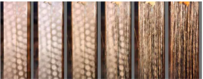
The axial strain of FRP samples was measured using particle image velocimetry (PIV) (White et al. 2003). High resolution images were taken during various stages of the test procedure. PIV is capable of tracking the movement of any pixel patches in a sequence of images. This allows for measuring the displacement field in the sample during the test. To measure the axial strain, the displacement of pixel patches similar to those shown in Figure 2 were tracked. The difference in axial displacement of the patches divided by their axial distance gives the strain in that direction. Figure 3 shows a sequence of pictures taken during the transient test. Since the PIV analysis tracks the pixel pattern around a certain point, difficulties arise when the surface texture changes due to thermal effects.
Pixel Patches
Figure 2 Square pixel patches (yellow squares) on FRP sheet used in PIV analysis.
Figure 3 Damage progress during test for specimen 2.1. Temperatures are 28, 77, 183, 200, 210 and 256 ˚C from left to right.
-.6.-
SBS based FOS were installed on the specimen along their longitudinal axis of symmetry as shown in Figure 1. The fibre was attached to the FRP sample at the ends using epoxy glue. The glued parts were kept outside the furnace. To further protect the bond between FOS and the coupon, a protective cover was placed on top of the glued fibre (Figure 4).
Figure 4 Fibre optic sensor and protective cover installation details.
6 RESULTS
Based on differential scanning calorimetry (DSC) and dynamic mechanical analysis (DMA) tests on the FRP material, Tg was determined to be 110˚C.
PIV analysis was performed to calculate the strain at several load levels for the test sample 1.1. Knowing the load level and the sample dimensions, these strain values were used to calculate the secant elastic modulus as reported in Table 2.
Table 3 shows the results of the steady-state tests. No significant loss of strength was observed in tests performed at temperatures below Tg. The elastic modulus as reported by the
manufacturer is 165 GPa which is in good agreement with the obtained results.
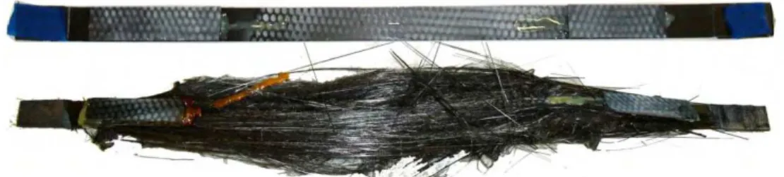
Figure 5 shows a sample coupon before and after a transient test while Figure 6 shows the secant modulus versus temperature during the transient test. The modulus of the material decreases as the temperature rises. The rate of reduction increases dramatically just above the glass transition temperature (110 ˚C).
Table 2 Modulus calculation results for room temperature test at different load levels; strain was calculated using PIV analysis.
Load (kN) Strain PIV Stress (MPa) Secant Modulus (GPa)
40 0.92% 1390 151
60 1.32% 2080 158
80 1.70% 2780 163
Table 3 Steady-state tension test results for FRP at high temperature.
Specimen ID Temperature (˚C) Width (mm) Peak load (kN) Strength (MPa) Strength Loss %
1.1 27 24.0 81.6 2830 0.0
1.2 110 24.0 73.1 2540 11.6
1.3 90 24.6 82.1 2780 0.7
-.7.-
Figure 5 CFRP specimen 2.1, transient test, before and after the test.
1.65 1.70 1.75 1.80 1.85 0 50 100 150 200 Secant Elastic Modulus (GPa) Temperature (˚ C)
Figure 6 Secant modulus for specimen 2.1 vs. temperature.
7 FULL-SCALE FIRE EXPERIMENTS
Two beams were constructed as a part of ongoing research on structural behaviour of FRP strengthened members in fire. The steel reinforced concrete beams were 3900 mm long and
400 mm deep with a 1220 mm wide flange (150 mm thick) and a 300 mm wide web. These
T-beams were strengthened with external FRP, and fire protection for the FRP was provided by sprayed insulation. These beams were then exposed to a standard ASTM fire while under sustained loading. FOS were attached to longitudinal steel bars to capture temperature and
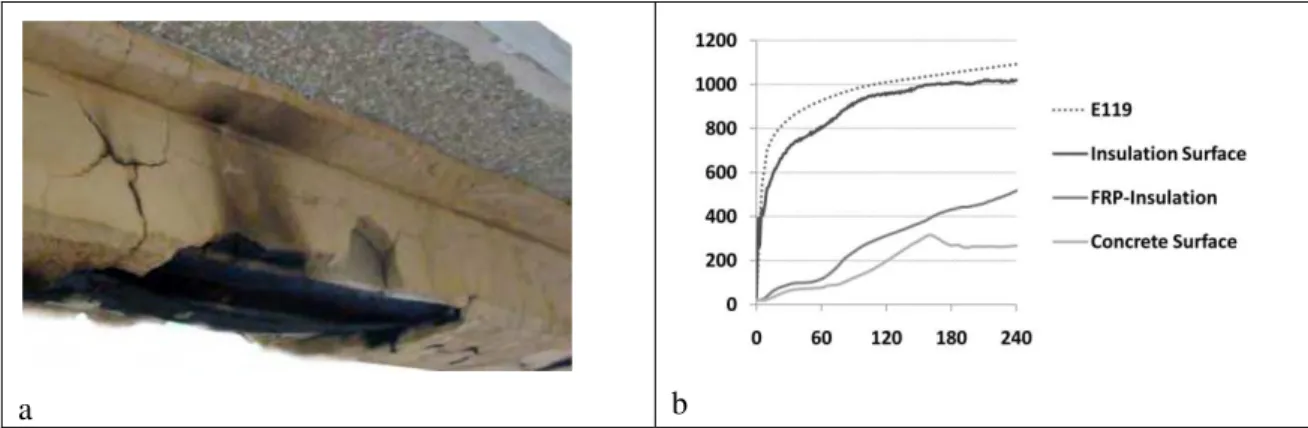
strain during the fire test of the beams (Figure 7). Figure 8-a shows the condition of beam
after four hours of exposure to standard fire. Both beams successfully resisted the sustained
applied load for more than four hours of fire exposure without structural failure. Figure 8-b shows the temperature distribution at the insulation surface, the FRP-insulation interface, and the FRP-concrete interface (concrete surface) at midspan of the T-beam.
B
2 6 2 8 2 9 3 0 2 7 2 1 2 0 1 6 1 2 9 1 0 1 4 1 8 1 3 1 7 1 1 1 5 1 9 2 5 8 2 2 2 3 2 4 4 1 4 0 FRP I nsulat ion FOS St rain gauge FOS St rain gauge Therm ocouple-.8.-
a b
Figure 8 (a) Beams after four hours of exposure to standard fire and (b) Temperature (˚C) vs. exposure time (min) at midspan of the T-beam.
8 CONCLUSIONS
This paper demonstrates various methods of temperature and strain measurement techniques suitable for structural health monitoring. The focus is placed especially on high temperature sensing.
For FRP coupon testing for tensile strength, no significant loss of strength occurred at temperatures below Tg, and the CFRP coupons preserved slightly more than half of their room
temperature strength even at temperatures above their Tg. This residual strength exceeds the strength requirements in most flexural strengthening applications provided that adequate bond can be maintained between the FRP and concrete. Further investigations need to be done to provide statistically reliable data on FRP behaviour at elevated temperatures.
Although PIV analysis is a convenient and accurate method of strain measurement, the analysis will not be suitable where the surface texture of the material is damaged.
9 ACKNOWLEDGMENTS
The authors would like to thank the Intelligent Sensing for Innovative Structures (ISIS) Canada Research Network and Sika Corporation for support of this research.
10 REFERENCES
Karter Jr., MJ 2009, Fire Loss in the U.S., During 2008, NFPA, Quincy, MA.
Kersey, A.D.; Dandridge, A. 1990, Applications of fiber-optic sensors," Components, Hybrids, and Manufacturing Technology, IEEE Transactions on , vol.13, no.1, pp.137-143.
Ravet, F., 2009, Submillimeter crack detection with brillouin-based fiber-optic sensors. IEEE sensors journal, 9(11), 1391.
White DJ, Take WA, Bolton, MD. 2003, Soil deformation measurement using particle image velocimetry (PIV) and photogrammetry. Ge´otechnique 53(7):619–631.
Zou L., Bao X., Afshar V. S., and Chen L., 2004, Dependence of the Brillouin frequency shift on strain and temperature in a photonic crystal fiber, Optics letters 29 (13): 1485.
Zeng X., Bao X., Chhoa C. Y., Bremner T. W., Brown A. W., DeMerchant M. D., G. Ferrier, A. L. Kalamkarov, and A. V. Georgiades, 2002, Strain measurement in a concrete beam by use of the Brillouin-scattering-based distributed fiber sensor with single-mode fibers embedded in glass fibre reinforced polymer rods and bonded to steel reinforcing bars, Appl. Opt. 41, 5105.