HAL Id: tel-02512896
https://tel.archives-ouvertes.fr/tel-02512896
Submitted on 20 Mar 2020
HAL is a multi-disciplinary open access archive for the deposit and dissemination of sci-entific research documents, whether they are pub-lished or not. The documents may come from teaching and research institutions in France or abroad, or from public or private research centers.
L’archive ouverte pluridisciplinaire HAL, est destinée au dépôt et à la diffusion de documents scientifiques de niveau recherche, publiés ou non, émanant des établissements d’enseignement et de recherche français ou étrangers, des laboratoires publics ou privés.
magnétiques : ses causes et ses effets
Mohamed Ali Nsibi
To cite this version:
Mohamed Ali Nsibi. Le déplacement asymétrique des parois de domaine magnétiques : ses causes et ses effets. Mesoscopic Systems and Quantum Hall Effect [cond-mat.mes-hall]. Université Grenoble Alpes, 2019. English. �NNT : 2019GREAY047�. �tel-02512896�
THÈSE
Pour obtenir le grade de
DOCTEUR DE LA COMMUNAUTE UNIVERSITE
GRENOBLE ALPES
Spécialité : Physique de la matière condensée
Arrêté ministériel : 25 mai 2016
Présentée par
Mohamed Ali NSIBI
Thèse dirigée par Gilles GAUDIN et co-encadrée par Ioan Mihai MIRON
préparée au sein du Laboratoire SPINTEC
et de l'École Doctorale de physique de Grenoble
Asymmetric magnetic domain walls
motion in a two-dimensional geometry:
causes and effects
Thèse soutenue publiquement le 16 octobre 2019, devant le jury composé de :
M. Jan VOGEL
Directeur de Recherche, Institut Néel, Président
M. Jean-Marie GEORGE
Directeur de Recherche, Unité Mixte de Physique CNRS/Thales, Rapporteur
M. Joo-Von KIM
Directeur de Recherche, Centre de Nanosciences et de Nanotechnologies, Rapporteur
M. Pietro GAMBARDELLA
Professeur, ETH Zürich, Examinateur
M. Reinoud LAVRIJSEN
Professeur assistant, Eindhoven University of Technology, Examinateur
M. Ioan Mihai MIRON
Chargé de Recherche, SPINTEC, Co-encadrant de thèse
M. Gilles GAUDIN
ii
List of Abbreviations
BLS – Brillouin light scattering technique BW – Bloch domain wall
CD – The Chiral Damping mechanism
CIDWM – Current-induced domain wall motion DMI – Dzyaloshinskii-Moriya interaction DRAM – Dynamic random-access memory DW – Magnetic domain wall
DWU-D – Up/down domain wall
DWD-U – Down/up domain wall
FIDWM – Field-induced domain wall motion FM – Ferromagnetic layer
GMR – Giant Magnetoresistance HDD – Hard disk drive
HM – Heavy metal layer
LLG – Landau-Lifshitz-Gilbert equation
MOKE – Magneto-optical Kerr effect microscopy MRAM – Magnetic random-access memory MTJ – Magnetic tunnel junction
NW – Néel domain wall
PMA – Perpendicular magnetic anisotropy SHE – Spin Hall effect
SIA – Structural inversion asymmetry SkHA – Skyrmion Hall angle
SkHE – Skyrmion Hall effect SOC – Spin-orbit coupling SOT – Spin-orbit torques
SPLEEM – Spin-polarized low energy microscopy SP-STM – Spin-polarized scanning tunneling microscopy SRAM – Static random-access memory
STT – Spin-transfer torques
TMR – Tunneling magnetoresistance
List of symbols
𝐴𝑒𝑥 – Exchange interaction stiffness
𝐷 – The DMI constant
𝑑 – Diameter of a circular magnetic domain / magnetic bubble 𝑯𝑲 – Magnetostatic ‘shape’ anisotropy effective field of a Bloch wall
𝑯𝑫𝑳 – The effective “damping-like” magnetic field
𝑯𝑫𝑴𝑰 – The local effective DMI field
𝑯𝒅𝒊𝒑 – Dipolar magnetic field
𝑯𝑭𝑳 – The effective “field-like” magnetic field
𝑯𝒕𝒉– The thermal magnetic field
𝑯𝒙 – The applied in-plane magnetic field
𝑯𝒛 – The applied out-of-plane magnetic field
𝑯𝒛𝒎𝒃 – The external out-of-plane field stabilizing magnetic bubbles
𝑱 – The charge current density vector
𝐾 – Magnetostatic ‘shape’ anisotropy of a Bloch wall 𝐾𝑑𝑖𝑝 – Dipolar energy constant
𝐾𝑒𝑓𝑓– Effective uniaxial anisotropy constant
𝑴 – The local magnetization 𝑀𝑠 – Saturation magnetization
𝒎 – The unit magnetization vector
𝒎𝑫𝑾 – The DW core magnetization unit vector
𝑛 – Topological charge of a skyrmion 𝒏𝑫𝑾 – the DW normal vector
𝑻𝑫𝑳 – The damping-like torque from SOT
𝑻𝒅𝒊𝒑– The dipolar torque
𝑻𝑭𝑳 – The field-like torque from SOT
𝑻𝜶 – The damping torque
𝑡𝐹𝑀 – Thickness of the ferromagnetic layer
𝑣𝐷𝑊 – The DW velocity
𝑣𝐷𝑈 – Velocity of the down/up DW
𝑣𝑆𝑘 – Velocity of the magnetic skyrmion bubble
𝑣𝑈𝐷 – Velocity of the up/down DW
𝛼, 𝛼0 – The isotropic Gilbert damping parameter
𝛼𝑐 – The chiral component of the damping parameter
∆ - DW width parameter
iv
𝜎𝐷𝑊 – Energy density of a DW
𝜃𝑆𝐻 – Spin Hall angle of a metal
𝜃𝑆𝑘𝐻 – The skyrmion Hall angle
𝜙𝑑 – The drift angle of the magnetic bubble
𝜙𝐽– The angle between 𝑱 and 𝒏𝑫𝑾
𝜙𝐽𝑚𝑎𝑥 – The angle of largest displacement of the DW µ0 – Magnetic permeability of vacuum
Contents
List of Abbreviations ... ii
List of symbols ... iii
Contents ... v
Introduction ... 1
I. State of the art ... 6
I.1. Energies in a ferromagnetic system ... 6
I.1.1. The Zeeman energy ... 7
I.1.2. The exchange energy ... 7
I.1.3. The magnetic dipolar energy ... 7
I.1.4. The magnetic anisotropy energy ... 9
I.2. Domain walls in perpendicular magnetic anisotropy films ... 9
I.2.1. Perpendicular magnetic anisotropy (PMA) thin films... 9
I.2.2. Domain walls in PMA materials ... 10
I.2.3. DW motion in PMA materials ... 11
I.3. Field-induced DW motion (FIDWM) ... 12
I.3.1. LLG equation ... 12
I.3.2. Displacement of a DW by a magnetic field ... 14
I.3.3. Flow regime of motion ... 15
I.3.4. Creep regime of motion ... 16
I.4. Current-induced DW motion (CIDWM) ... 17
I.4.1. Spin-transfer torques (STTs) ... 17
I.4.1.1. Adiabatic STT ... 18
I.4.1.2. Non-adiabatic STT ... 18
I.4.1.3. Displacement of a DW by STT ... 19
I.4.2. Spin-orbit torques (SOTs) ... 20
I.4.2.1. Rashba Effect and Spin Hall effect (SHE) in SIA materials ... 21
I.4.2.2. The field-like term of SOT ... 22
I.4.2.3. The damping-like term of SOT ... 24
I.4.2.4. Displacement of DWs by SOTs ... 26
I.5. Chiral DWs motion in SIA materials ... 28
I.5.1. Dzyaloshinskii-Moriya Interaction (DMI) ... 28
I.5.2. Chiral Néel DWs induced by DMI ... 29
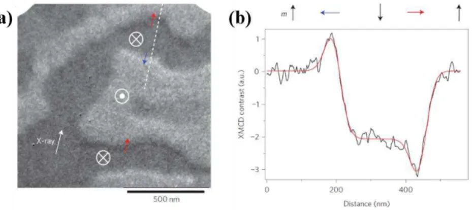
I.5.3. Direct evidence of Chiral Néel walls in SIA materials ... 30
I.5.4. DW motion in the presence of DMI ... 32
vi
I.5.4.2. The DMI + SOT mechanism for CIDWM ... 33
I.5.5. Techniques to quantify DMI ... 36
I.5.5.1. Techniques not based on DW motion ... 36
I.5.5.2. Techniques based on DW motion ... 37
I.6. Chiral Damping in DWs ... 43
I.6.1. The experimental evidence of Chiral Damping ... 43
I.6.1.1. The failure of the DMI-induced asymmetry mechanism ... 43
I.6.1.2. The proposal of chiral dissipation in FIDWM ... 44
I.6.1.3. A possible description of the Chiral Damping ... 45
I.6.2. Phenomenology and origin of the Chiral Damping ... 47
I.6.3. The coexistence of different chirality-induced asymmetries ... 48
Conclusions ... 51
II. Experimental techniques... 54
II.1. Samples fabrication ... 54
II.1.1. Thin films deposition ... 54
II.1.2. Fabrication of wires for DW motion ... 54
II.2. DWs under Magneto-optic Kerr effect (MOKE) microscopy ... 55
II.3. DW motion by the injection of an electric current ... 57
II.3.1. Current-induced DW Motion set-up... 57
II.3.2. DW motion in the presence of external magnetic fields ... 58
II.3.3. Measurements of DW motion ... 58
III. The asymmetric non-collinear current-induced DW motion in SIA materials ... 61
III.1. The non-collinear DW motion ... 61
III.2. Asymmetric distortion of magnetic circular domains ... 65
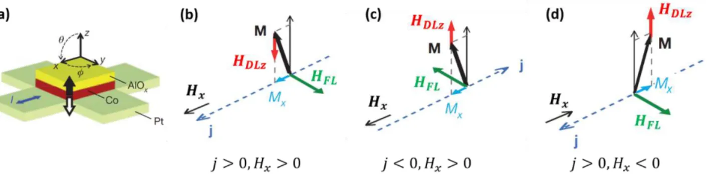
III.3. Non-collinear DW motion in Pt/Co/AlOx ... 66
III.3.1. The DMI + SOT mechanism in the flow regime ... 67
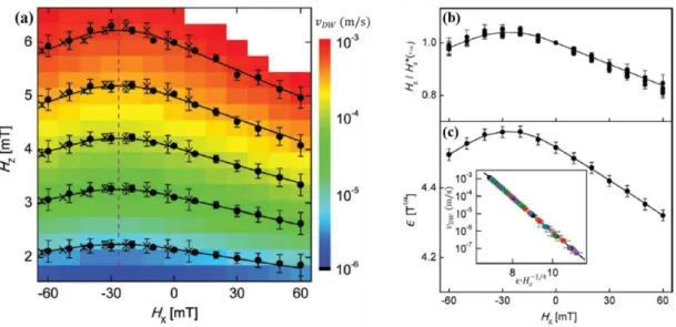
III.3.2. The DW motion in the presence of an in-plane magnetic field ... 69
III.3.2.1. Effects of the in-plane magnetic field ... 69
III.3.2.2. Measurement of the angle 𝝓𝑱𝒎𝒂𝒙 ... 73
III.3.3. Asymmetric DW motion in the creep regime ... 75
III.4. Non-collinear DW motion in Pt/Co/Pt ... 76
III.4.1. The presence of the DMI in Pt/Co/Pt ... 76
III.4.2. Asymmetric non-collinear DW motion ... 78
III.4.3. The numerical collective coordinate model ... 79
III.4.4. The role of the thermal fluctuations ... 81
III.4.4.1. The DW motion in the absence of the thermal fluctuations ... 81
III.4.4.2. The DW motion in the presence of the thermal fluctuations ... 82
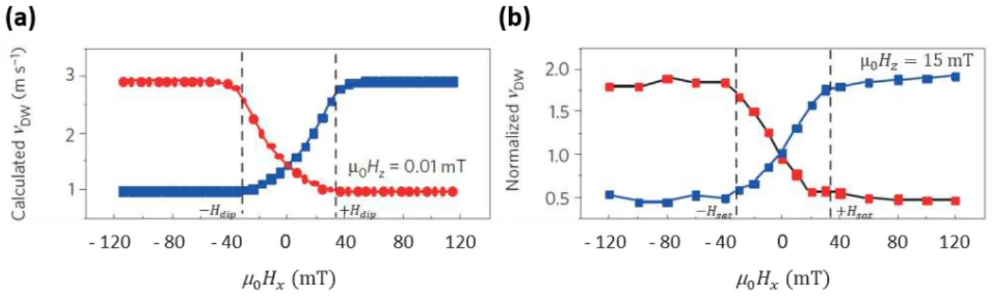
III.4.5.1. Effects of the in-plane magnetic field ... 84
III.4.5.2. The role of the Chiral Damping in CIDWM ... 88
Conclusions ... 93
IV. The DW tilt in SIA materials ... 95
IV.1. The formation of a DMI-induced DW tilt ... 95
IV.2. The DW tilt and the non-collinear DW motion ... 96
IV.3. The DW tilt in Pt/Co/AlOx ... 97
IV.4. The DW tilt in Pt/Co/Pt ... 98
Conclusions ... 99
V. The extrinsic mechanism of the Skyrmion Hall Effect ... 101
V.1. The intrinsic SkHE ... 102
V.1.1. Magnetic skyrmions... 102
V.1.2. Current-induced motion and the SkHE... 103
V.1.2.1. The emergent electromagnetism ... 103
V.1.2.2. The Thiele Equation of motion ... 105
V.1.2.3. The Skyrmion Hall angle (SkHA) ... 107
V.1.2.4. Experimental observations of the intrinsic SkHE... 107
V.1.3. The intrinsic SkHE and the asymmetric DW motion in the non-collinear configuration . 109 V.2. Chiral magnetic bubbles in Pt/Co/Pt and Pt/Co/AlOx ... 110
V.2.1. Formation of chiral magnetic bubbles ... 110
V.2.2. Stabilization of chiral magnetic bubbles with an out-of-plane field ... 111
V.2.3. Vanishing intrinsic SkHE in Pt/Co/Pt and Pt/Co/AlOx ... 112
V.3. The emergence of the extrinsic SkHE ... 113
V.3.1. The effects of the asymmetric non-collinear DW motion on the skyrmion bubbles ... 113
V.3.1.1. The distortion of the skyrmion bubbles into ellipses in Pt/Co/Pt ... 114
V.3.1.2. The “apparent” SkHE in Pt/Co/Pt under low current densities ... 115
V.3.1.3. Hopping-like motion in Pt/Co/Pt under large current densities ... 118
V.3.2. Evidence of “extrinsic” SkHE in Pt/Co/AlOx ... 119
V.3.2.1. The skyrmion bubbles motion under low current densities... 119
V.3.2.2. The skyrmion bubble motion under large current densities ... 120
V.3.3. The mechanism of the extrinsic SkHE ... 123
V.3.4. The extrinsic SkHE and magnetic skyrmion dynamics ... 124
Conclusions ... 126 General conclusions ... 128 Appendix ... 132 References ... 156 Résumé ... 172 Abstract ... 173
Introduction
In magnetism, research covers rich and different topics. Among these, we have the investigation of the microscopic origin of the magnetization (strongly correlated electron systems, frustrated magnetism, etc.) and nanomagnetism which focuses on the collective behaviors of the magnetization (magnetization dynamics, magnonics, etc.). In nanomagnetism, the dynamics of domain walls (DWs), skyrmions or vortex is attractive. These magnetic objects are interesting from both fundamental and technological points of view. They exhibit many exotic properties that are very promising for novel spintronics devices and applications. Spintronics, where magnetism and electronics are combined, offers the opportunity to control the local magnetization of a material by the spin of a free conduction electron or vice versa. Spintronics has emerged as a research field after the discovery of three major effects. The first effect is the Giant Magnetoresistance effect (GMR), reported in 1988 and rewarded by a Nobel Prize in 2007 that was jointly attributed to A. Fert and P. Grünberg. Subsequently, two complementary phenomena of GMR were evidenced; the Spin-transfer torque (STT) followed by the Tunneling Magnetoresistance effect (TMR). GMR is the change in the electrical resistance of a multilayered device upon the modification of its magnetic state. The multilayered device consists of two ferromagnetic layers that are separated by a conducting non-magnetic spacer. The relative orientation between magnetizations of the two ferronon-magnetic layers defines the device magnetic state, i.e. whether they are parallel or anti-parallel. STT allows changing the magnetic state by the transfer of angular momentum that is mediated via a spin-polarized electric current flowing from one ferromagnetic layer to another. When the non-magnetic spacer is an insulating oxide layer, we speak instead of a TMR and the device is called a Magnetic Tunnel Junction (MTJ). In MTJs, the difference in resistance can reach high ratios up to several hundred percent. The implementation of these effects in Hard Disk Drives (HDD) has led to a significant enhancement of the storage density capacity, reaching nowadays more than 1 Tbit/inch2. This is one example of the
huge impacts that spintronics has been bringing to the technology and the industry of electronic devices.
Many ideas and proposals have then emerged to make use of spintronics potential in higher levels of the memory hierarchy where the devices are based on CMOS technology. For years, the development of CMOS devices has been following the Moore’s law that predicts a density increase (number of components per integrated circuit) by a factor of two each year. However, it is not possible to extrapolate such a trend to the indefinite future. Major challenges and physical limits like thermal stability, power leakage and power consumption impede the scaling of CMOS devices. In order to overcome these hurdles, an alternative approach relies on spintronics, as non-volatility, high data retention and reduced power consumption in the static mode of magnetic memories are desirable. Nevertheless, CMOS memory devices are still advantageous since they have fast bit access/write time rates like in Static random-access memory (SRAM) typically found in the central processor unit cache of a computer. In return, SRAM has a low density and high operational power consumption. Dynamic random-access memory (DRAM) located in an intermediate level in the memory hierarchy is slower but has a higher density than SRAM. In any case, SRAM and DRAM are volatile. Therefore, development of non-volatile scalable magnetic states manipulated at faster rates (high-speed data transfer), at low power and with low bit failure rate is required in order to have spintronics devices embedded in or even replacing SRAM and/or DRAM.
Such a spintronics device is the Magnetic random-access memory (MRAM) that unlike HDD has a much faster bit access time. MRAMs are composed essentially of nano-pillar-patterned MTJs whose magnetic state defines the encoded binary data (either “0” or “1”). The STT-MRAM is attractive because it is non-volatile and scalable. To write bits, electric current flows vertically through the MTJ and controls the magnetic state by STT mechanism. The read out is ensured by the TMR effect. In this technology, writing and reading schemes share the same electric current path accelerating the aging of the tunnel barrier. This is disadvantageous when aiming for a fast switching
2
rate as it requires large current densities. STT devices suffer as well from an incubation delay that is enhanced by thermal fluctuations. Consequently, the switching time distribution can be several nanosecond wide. Unintentional bit write event can then occur during the reading operation for example.
In order to optimize the STT-MRAM, a great effort has been devoted for the development of ultrathin ferromagnetic films with perpendicular magnetic anisotropy (PMA) that can be implemented in MTJs. PMA materials are interesting thanks to their high thermal stability, which provides a high data retention. The Pt/Co/AlOx stack is a PMA structure that was initially developed to be a lower electrode for MTJs. In this structure, PMA originates from the strong spin-orbit coupling (SOC) at interfaces that is induced by the structural inversion asymmetry (SIA). Research studies carried out in this stack have put in evidence a new efficient mechanism for the current-induced magnetic switching through SOC. The charge to spin conversion from the spin Hall Effect (SHE) and/or the Rashba effect when an electric current flows in the plan of the stack promotes Spin-orbit torques (SOT) that act on the local magnetization of the ferromagnetic layer. A new concept of SOT-MRAM has then emerged. Henceforth, the writing operation is based on an electric current injected in-plane whereas the current flowing perpendicularly to MTJ is used only for the reading operation. Although this three terminal geometry is more demanding in terms of size, it has the advantage to decouple writing and reading schemes solving some issues of the STT-MRAM. Consequently, the junction experiences less stress from the electric current and the two processes can be optimized independently. The MTJ exhibits then a better endurance as there are reports of a robust SOT-switching up to over 1012 repeated cycles at current densities up to 4 1012 A.m-2. The SOT-based
magnetic switching has also faster time rates. The spin accumulation at the interface that leads to SOT is orthogonal to the quiescent state of the magnetization of the ferromagnetic layer. It reduces thereby the incubation delay compared to STT. Actually, reliable and reproducible magnetic switching were obtained with current pulses as short as 200 ps in Pt/Co/AlOx and Ta/CoFeB/MgO stacks. By offering as many functionalities as the STT-MRAM, these characteristics make the SOT-MRAM very competitive and a potential candidate to replace DRAM and SRAM in the memory hierarchy.
In SOT-MRAM, the magnetic switching in PMA films takes place through nucleation of DWs and their subsequent propagation. DWs are very thin (~ 5 nm), much thinner than the size of a typical device. A large DW velocity is mandatory to have a fast switching time. Further on, the critical switching current is mostly dependent on the DW mobility rather than on the initial nucleation barrier. The control of the DW motion would allow then partial and reliable switching that could be implemented to develop memristor devices for neuromorphic computing applications. Besides this idea, S. S. Parkin, in 2004 at IBM, proposed another type of devices that is also based on the DW motion. It is called the racetrack memory where series of magnetic domains, corresponding to encoded bits, are shifted towards a read/write head by the injection of a spin-polarized electric current. Magnetic domains are separated by DWs that can be displaced through STT in the direction of the moving electrons. Moreover, tracks can stand vertically giving access to three-dimensionality thus improving the storage capacity of the device. This concept is then promising for large density and fast random-access memories. Its feasibility relies on fast and reproducible DW motion at low critical current densities.
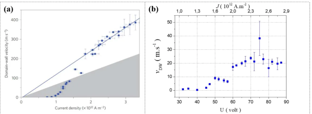
During several years, intensive efforts from many research groups did not succeed in obtaining such desirable features of the DW motion with the STT mechanism. The observation of a fast motion, up to 400 m.s-1 against the electron flow, in the Pt/Co/AlOx stack by I. M. Miron et al. in 2011 was
a breakthrough. This efficient DW motion could not be explained by STT and was attributed to the combined action of SOT and the interfacial Dzyaloshinskii-Moriya interaction (DMI). DMI is a consequence of SIA in this kind of materials. It ensures that DWs are driven by SOT in a unidirectional motion, i.e. either in or against the electron direction. DMI has also enabled the observation of other magnetic textures such as skyrmions. An intensive effort is currently in progress to optimize DMI for the stabilization of magnetic skyrmions with a sub-10 nm size. It was predicted that magnetic skyrmions require low current densities, compared to DWs, to be manipulated and are
less disturbed by the presence of disorder in materials. They hold then the promise for more energy efficient spintronic devices for either logic or ultra-high-density data storage applications. It is therefore crucial to investigate in depth the roles of SOT and DMI in the dynamics of these magnetic textures, e.g. DWs and magnetic skyrmions.
Concerning SOT, they act on the finite average magnetization of the DW (the DW core magnetization). Consequently, SOT depend on the relative angle between the electric current direction and the DW core magnetization. Thus, an oblique injection of the electric current with respect to the DW allows modifying the action of SOT. It is called the DW motion in a “non-collinear configuration”. C. K. Safeer et al. evidenced in 2015 an asymmetric DW motion in such a geometry by studying DWs in Co/AlOx nanowires patterned on top of a Pt layer. On the one hand, by taking advantage of the asymmetric DW motion, C. K. Safeer et al. designed a shape-controlled magnetic switching that helped to demonstrate the field-free SOT magnetic switching. On the other hand, the asymmetric DW motion in the non-collinear geometry cannot be explained by the SOT + DMI mechanism, which calls for a more complete and complex model. Therefore, it is essential to pursue the study of the non-collinear DW motion. It is also important to perform this study in various SIA materials. This will allow understanding the asymmetric DW motion that is paramount to develop efficient and flexible magnetic switching schemes.
As for DMI, it defines the DW equilibrium configuration in SIA materials. For instance, the orientation of the DW core magnetization depends on the magnitude of the DMI. It is then possible to identify the DMI by modulating the DW core magnetization. Such a modulation can be achieved using an external magnetic field oriented in the plane of the structures. In order to understand the role of DMI, we investigate the DW motion in the presence of an in-plane magnetic field. By studying DWs driven by magnetic fields in the Pt/Co/Pt stack, E. Jué et al., identified, in 2015, a new mechanism induced by SIA. It is the Chiral Damping mechanism. It consists in a magnetic damping that depends on the DW chirality, i.e. the direction of rotation of the magnetization within the DW. This new mechanism enriches the understanding of magnetization dynamics and implies the reconsideration of reports of the DW motion. A first step will be to explore the role of Chiral Damping in the current-induced DW motion.
In this context, the main objective of this thesis was to provide a more complete picture of magnetization dynamics. I have studied then the motion of different magnetization textures (DWs and magnetic bubbles). To push forward the understanding of SOT, DMI and the Chiral Damping, I have chosen to study the DW motion in a non-collinear geometry relative to the injected current and in the presence of an external in-plane magnetic field. I have carried out this study in two different Pt/Co-based heterostructures with PMA. The investigated structures are Pt/Co/AlOx and Pt/Co/Pt. The former structure has a large SIA whereas the latter is a low SIA material. The question is then how characteristics of the DW motion change with the variation of SIA. By comparing results in these two structures, this thesis unveils the dependence of the DW motion on the extent of SIA. My results confirm the failure of the DMI + SOT mechanism and are in part explained by including the Chiral Damping along with the DMI and SOT. I have evidenced then the interplay between chiral energy and chiral dissipation in SIA materials. The DW motion in the non-collinear geometry has been found to exhibit the similar features in Pt/Co/AlOx and Pt/Co/Pt. I have then tried to find out what consequences such a motion can induce. Following this, I have discovered that the non-collinear DW motion can have a significant effect on current-induced skyrmion bubbles motion. The results of this thesis give new insights on dynamics of DWs and skyrmion bubbles in SIA materials. These efforts will help to understand magnetic textures interactions with electric current allowing the design of desirable future spintronics devices with well-defined functionalities.
This manuscript is divided into five chapters.
In the first chapter, I present the state of the art of the DW motion in PMA multilayers. This introduction is necessary to interpret our experimental results described in chapters three, four and
4
five. We review the spin-orbit coupling induced mechanisms in SIA ultrathin layers. A special attention is given to the following mechanisms: SOT, DMI and Chiral Damping.
In the second chapter, I describe the used experimental techniques in this thesis. I describe the fabrication process of samples and introduce the magneto-optical Kerr effect employed to image the motion of the magnetic textures. In the end, I present the experimental set-up to inject the electric current and the methods to measure displacements and velocities of DWs.
The third, fourth and fifth chapters are dedicated to the experimental results and their interpretation. In the third chapter, I present the experimental observations of the DW motion in the non-collinear geometry relative to the electric current. This motion is asymmetric in both structures. It is even maintained upon the variation of the DW internal structure by an external in-plane magnetic field. The interpretation of these findings using a numerical model reveals the significant role of the Chiral Damping along with the DMI and SOT in the current-induced motion of DWs. However, these three combined phenomena remain insufficient to account for all observations of DWs dynamics in both the large and the low SIA materials.
In the last two chapters, I present the two important consequences of the non-collinear DW motion. First, I have investigated the possible relation between the non-collinear DW motion and the formation of the DW tilt in wires in the fourth chapter. I have experimentally evidenced that the former mechanism is responsible for the emergence of the latter effect in the Pt/Co/AlOx structure.
Second, the asymmetric DW motion in the non-collinear geometry shows striking similarities with the so-called skyrmion Hall effect (SkHE). These similarities have led us to extend the scope of this thesis towards the investigation of current-induced motion of skyrmion bubbles. In the fifth chapter, I describe the unexpected experimental results of this study in both Pt/Co/Pt and Pt/Co/AlOx stacks. These results have demonstrated a new mechanism of skyrmion bubbles deflection; an extrinsic Skyrmion Hall effect. The asymmetric non-collinear DW motion generates such a contribution to the SkHE. This new concept enriches the scope of magnetic skyrmions dynamics.
6
I. State of the art
In this chapter, I will introduce some concepts of solid-state magnetism that are essential to address the experimental work presented in the following chapters. During the thesis, the focus was on magnetic domain wall (DW) motion in ultrathin layers with perpendicular magnetic anisotropy (PMA) and structural inversion asymmetry (SIA). I first present magnetic interactions that govern the ferromagnetic state, lead to the formation of DWs and give rise to PMA. Next, I describe field-induced DW motion (FIDWM) and current-field-induced DW motion (CIDWM) in materials with PMA. Further, I discuss the emergent phenomena from SIA and their impact on DW motion: spin-orbit torques (SOT), the Dzyaloshinskii-Moriya interaction (DMI) and the novel Chiral Damping concept.
I.1. Energies in a ferromagnetic system
In solid materials, magnetism arises from the arrangement within an atom, according to the Hund’s rule, of quantized magnetic dipole moments associated to spins of electrons. A spin is an intrinsic angular momentum carried by an electron, depicted as a particle that spins or precess around its own axis. This picture is misleading as the spin has a quantum nature with only two states: a spin up or a spin down. If the arrangement of spins leads to a partially filled shell, the atom gets a net magnetic moment. In materials called paramagnetic materials, these magnetic moments point in random directions giving a total zero magnetization. They yield a net magnetization when they align parallel to an external magnetic field. Other materials involve magnetic moments that align spontaneously in the same direction without an external magnetic field. They are the anti-ferromagnetic, ferrimagnetic or ferromagnetic materials characterized by a spontaneous (or a remanent) magnetization 𝑀𝑠. It is the net magnetic moment per unit volume (or mass). Depending on
their mutual interaction, the magnetic moments of neighboring atoms align parallel in anti-ferromagnetic and ferrimagnetic materials or parallel in anti-ferromagnetic materials. Since in this work we deal with ferromagnetic thin layers, we will consider only magnetic moments that align spontaneously parallel to each other.
In a ferromagnet, thermal fluctuations perturb the mutual orientation of neighboring magnetic moments. Above a certain temperature called the Curie temperature 𝑇𝐶, they end up destroying the
magnetic order and the material is henceforth paramagnetic (𝑀𝑠 = 0). Since we are interested in
ferromagnetic materials that can be used in everyday life from domestic refrigerator magnets to sensors and data storage devices, we will restrict ourselves to materials with 𝑇𝐶 above the room
temperature of 300 𝐾. This is satisfied for example by 3d transition metals (Fe, Co, and Ni) and a wide variety of their alloys [Levy, Fanter and Wolf, 1972].
All atomic magnetic moments of a macroscopic ferromagnet are not necessarily aligned in the same direction. The magnetic structure can be composed of microscopic regions, called magnetic domains, within which all magnetic moments are aligned. The boundary separating adjacent regions is called the DW. The stabilization of such complex structures and patterns results from the minimization of the total energy in the ferromagnetic system. For instance, the total energy is essentially the sum of several contributions commonly; the Zeeman interaction 𝜖𝑧, the exchange
interaction 𝜖𝑒𝑥, the dipolar interaction 𝜖𝑑𝑖𝑝 and the magnetic anisotropy interaction 𝜖𝑎𝑛𝑖𝑠 [O’Handley, 2000; Buschow and de Boer, 2003].
I.1.1. The Zeeman energy
The Zeeman energy term corresponds to the interaction between the local magnetization1 𝑴
and a magnetic field. This interaction tends to align 𝑴 parallel to the applied magnetic field. It writes as follow:
𝜖𝑧 = −µ0𝑴. 𝑯𝒂𝒑𝒑 (I.1)
where µ0 is the magnetic permeability of vacuum and 𝑯𝒂𝒑𝒑 the external applied magnetic field.
I.1.2. The exchange energy
The exchange interaction 𝜖𝑒𝑥 is a short-range interaction characterized by the exchange constant 𝒥𝑖𝑗 that couples neighboring magnetic moments 𝑺𝒊 and 𝑺𝒋. It arises from quantum
mechanical phenomena that promotes magnetic moments to align in the same direction (𝒥𝑖𝑗 > 0) or in opposite directions (𝒥𝑖𝑗 < 0). 𝜖𝑒𝑥 writes as follow:
𝜖𝑒𝑥= − ∑ 𝒥𝑖,𝑗 𝑖𝑗𝑆𝑖𝑆𝑗cos ∅𝑖,𝑗 (I.2)
where ∅𝑖,𝑗 is the angle between 𝑺𝒊 and 𝑺𝒋. There is an energy cost when magnetic moments are
misaligned. This interaction does not specify any particular orientation for the moments. For micromagnetic considerations, the discrete system of magnetic moments is modeled by a continuously varying magnetization. The exchange interaction writes then as an integral over the volume of the ferromagnet.
𝜖𝑒𝑥= ∫ 𝐴𝑒𝑥[(∇𝑀𝑥)2+ (∇𝑀𝑦)2+ (∇𝑀𝑧)2] 𝑑𝑉 (I.3)
The misalignment is accounted for by the gradients of the components of the local magnetization 𝑴 𝐴𝑒𝑥 is the exchange interaction stiffness that incorporates the exchange constant 𝒥𝑖𝑗 and the structure
of the material. If only the exchange interaction existed, a ferromagnetic material would be a single macro-domain with uniform magnetization.
This short-range interaction has a characteristic length; the exchange length 𝑙𝑒𝑥= √2𝐴𝑒𝑥⁄(µ0𝑀𝑠2). The exchange interaction is considered negligible between two moments
separated by a distance much larger than 𝑙𝑒𝑥 and all moments located within this length can be
modeled as a unique acting macro-spin. By taking values of 𝐴𝑒𝑥 and 𝑀𝑠 available in literature for
comparable structures to ours [Metaxas et al., 2007; Miron et al., 2010], 𝑙𝑒𝑥 is estimated to be more
than 4 nm whereas the thicknesses of the ferromagnetic layers considered in this thesis are less than 1 nm. In consequence, we assume that the magnetization 𝑀 does not depend on the position along the normal to the film (the z-axis) and that the magnetic structure is two-dimensional.
I.1.3. The magnetic dipolar energy
A magnetic moment, by analogy the local magnetization 𝑴, is a magnetic dipole whose magnetic stray field 𝑯𝒅𝒊𝒑 lines are curling around to fulfill the magnetic flux closure, as there can be
1
The local magnetization 𝑴 (or simply “magnetization”) corresponds to the density of all magnetic moments in a ferromagnet. Inside the magnetic material, 𝑴 is a function of the position vector 𝒓 with 𝑴(𝒓) =𝑑𝑟𝑑ḿ3 and ḿ= ∭ 𝑴(𝒓)𝑑𝑟3 (ḿ the net magnetic moment
8
no free magnetic monopoles according to the Gauss’s law for magnetism, ∇µ0(𝑯 + 𝑴) = 0 . In a
ferromagnetic material, 𝑯𝒅𝒊𝒑 is then antiparallel to a neighboring 𝑴 destabilizing the single domain configuration favored by the exchange interaction. We refer to this gain in the ferromagnetic energy as the magnetic dipolar interaction. Locally, this interaction is small compared to the exchange interaction but it is a long-range interaction that can influence the spatial distribution of the magnetization. Since a dipole can be viewed as an association of positive and negative charges, the dipolar interaction can be modeled by the interaction between 𝑴 and 𝑯𝒅𝒊𝒑 produced by those charges.
For ultrathin magnetic layers (Figure I.1), the strength of 𝑯𝒅𝒊𝒑 depends strongly on the orientation
of 𝑴 with respect to the thin film plane. For a magnetization 𝑴 uniformly oriented along an axis in the film plane (Figure I.1.a), the uncompensated positive and negative charges are far away from each other. The resulting 𝑯𝒅𝒊𝒑 is small. In the contrary, when 𝑴 is aligned along the film thickness (Figure I.1.b), the magnetic charges are closer to each other creating a large 𝑯𝒅𝒊𝒑. In order to
minimize charges at the surfaces and thus to reduce the dipolar interaction, the ferromagnet breaks into multiple smaller domains at the expense of the exchange interaction (Figure I.1.c).
Figure I.1 Distributions of magnetostatic charges in a thin magnetic film. Magnetization are (a) in-plane and (b)-(c) out-of-plane. The
green arrows indicate the local orientation of the magnetization 𝑴 inside the magnetic film. The magnetostatic charges are represented in orange. The uncompensated charges emerge at the surface of the film and they create a dipolar field 𝑯𝒅𝒊𝒑 (orange arrow) inside the material. In order to reduce 𝑯𝒅𝒊𝒑, the magnetic film breaks into domains (c).
The energy due to the dipolar field 𝑯𝒅𝒊𝒑, also called the shape anisotropy or the magnetostatic
energy is expressed as [Hubert & Schäfer 2009]: 𝜖𝑑𝑖𝑝 = −1
2µ0∫ 𝑴. 𝑯𝒅𝒊𝒑𝑑𝑟3 (I.4)
Here, 𝑯𝒅𝒊𝒑 is related to the magnetization 𝑴 through (for a uniform magnetization)
𝑯𝒅𝒊𝒑= −𝑵 ∙ 𝑴 (I.5)
where 𝑵 is the demagnetizing tensor (𝐻𝑑𝑖𝑝𝑖 = − ∑ 𝑁𝑗 𝑖𝑗𝑀𝑗) with i,j = x,y or z. It is very difficult to calculate 𝑁 and to have 𝑯𝒅𝒊𝒑 for an arbitrary shaped magnetic material. Nevertheless, it can be
analytically calculated for some common geometries in literature [Aharoni 1998]. Qualitatively, as we can infer from Figure I.1, it is energetically favorable for the magnetization to orient in-plane along the largest dimension of the film so to have less magnetic charges. This is valid unless we take into consideration an additional energetic anisotropic term.
I.1.4. The magnetic anisotropy energy
A ferromagnetic material can be anisotropic. In other words, it has a preferential direction, for example an “easy axis” (along which the magnetization prefers to point) and a “hard axis”. The magnetization does not orient along the hard axis unless a large external magnetic field is applied. The crystal structure of the material is often the source of such anisotropy. An easy axis corresponds usually to a particular crystallographic axis. That is why the magnetic anisotropy is referred to as the “magnetocrystalline anisotropy”. The relationship between the crystal structure and the magnetization fundamentally arises from spin-orbit coupling (SOC). The spin-orbit interaction couples the spin of an electron to its orbital momentum. The crystal field from the lattice breaks the symmetry of the orbital momentum setting thus a preferential orientation for magnetic moments. In the simplest case of an uniaxial anisotropy, the magnetic anisotropy energy can be written as:
𝜖𝑎𝑛𝑖𝑠 = 𝐾𝑢sin2𝜃 (I.6)
where 𝐾𝑢 is the uniaxial anisotropy constant and 𝜃 the deviation angle of the magnetic moment from
the easy axis (the polar angle). The magnetocrystalline anisotropy can originate from both the bulk and the interface. The engineering of the interface contribution can thus induce an out-of-plane easy axis in ultrathin ferromagnetic films. Such stacks with perpendicular magnetic anisotropy have been attracting a considerable attention for more than a decade. One reason behind this interest is the study of DWs whose dynamics hold the promise to be fast, efficient and reproducible.
I.2. Domain walls in perpendicular magnetic anisotropy films
I.2.1. Perpendicular magnetic anisotropy (PMA) thin films
The investigated magnetic layers have thicknesses less than 1 nm. The shape anisotropy through the dipolar field, in consequence, is large and tries to keep the magnetization in the plane. In the meantime, by properly engineering the “interfacial anisotropy”, it is possible to bring the easy axis out-of-plane providing thus these layers with PMA.
The interfacial anisotropy in thin films is well established and was evidenced in various multilayers with heavy-metal/ferromagnet (HM/FM) and ferromagent/oxide (FM/Ox) interfaces [Dieny & Chshiev 2017]. To name a few, we have as HM/FM interfaces Pt/Co, Ta/CoFeB, W/CoFeB, Ta/CoFe, Hf/CoFeB, Pd/FePd etc. [Bandiera et al. 2011; T. Liu et al. 2012; Ahn & Beach 2013; Lee et al. 2014]. As for FM/Ox interfaces, we cite Co/AlOx and CoFeB/MgO [Lacour et al. 2007; Rodmacq et al. 2009; A Manchon et al. 2008; A. Manchon et al. 2008].
For the HM/FM interface, the large spin-orbit interaction plays the key role in promoting the PMA as HMs have a strong SOC. The efficiency of such coupling depends strongly on the state of the interface. Varying the thickness of the HM or the FM has an impact on the perpendicular magnetic anisotropy (PMA) confirming its interfacial origin [Sokalski et al. 2012]. On the contrary, the spin-orbit interaction is weaker in FM/Ox interfaces [Monso et al. 2002]. However, the degree of its oxidation tunes the magnetic anisotropy. An optimal oxidation of this interface allows having a strong PMA whereas an over- or under-oxidation reduces it drastically [Rodmacq et al. 2003]. The thermal annealing, as it helps oxygen atoms to migrate towards the interface thus optimizes its oxidation, gives also a large PMA [Rodmacq et al. 2009]. The PMA originates from an overlap between the Oxygen 2pz and the transition metal 3-d orbitals confirmed by ab-initio calculations
10
In the present work, the investigated systems are Pt/Co/Pt and Pt/Co/AlOx. In these systems, both interfaces of the FM layer contribute to the magnetic anisotropy as described above. They exhibit a stable PMA at room temperature.
I.2.2. Domain walls in PMA materials
As we have already seen in section I.1.3, in order to reduce its dipolar field, a ferromagnetic material tends to demagnetize at equilibrium in such a way that the net total magnetization is small or zero. For instance, it gets divided into magnetic domains within which magnetization is uniform (Figure I.1). The separation between adjacent magnetic domains is the domain wall (DW). A DW is the region in which the magnetization 𝑴 rotates gradually between the orientations of the two domains (between up and down in PMA materials). Forming a DW costs energy; an exchange energy term, as magnetic moments within the DW are not parallel with respect to each other and an anisotropy energy term because magnetic moments deviate from the easy axis. The formation of DWs is then the outcome of the competition between the dipolar, exchange and magnetic anisotropy interactions. This competition dictates the DW width parameter ∆ that writes as [O’Handley, 2000]:
∆= √𝐴𝑒𝑥⁄𝐾𝑒𝑓𝑓 (I.7)
A large PMA tends to make the DW thinner as it reduces the number of the magnetic moments not aligned along the easy axis. If the DW is very thin, the angle between the neighboring magnetic moments is important so the cost in exchange energy is considerable. The exchange interaction favors then a large DW. In ultrathin films with an out-of-plane anisotropy, DWs are usually narrow (≲ 10 nm) and adopt either a Bloch or a Néel configuration (Figure I.2). When the magnetization rotates in the plane of the wall (around the x-axis in Figure I.2), the DW is of the Bloch-type. It is a Néel wall when it rather rotates in the plane normal to the wall (defined by the z- and x-axis in Figure I.2).
Figure I.2 Schematic diagrams of magnetic DWs in thin films with PMA. (a) Bloch wall: 𝑴 rotates inside the DW plane. (b) Néel wall:
𝑴 rotates perpendicular to the DW plane. Here, the stripe width 𝑤 is much larger than the DW width ∆ (𝑤 ≫ ∆). The dipolar energy dictates the stable configuration of a DW. The magnetostatic charges are depicted in orange and the arrow corresponding to the dipolar field 𝑯𝒅𝒊𝒑 scales with its magnitude.
Having one of this two DW configurations relies on the dipolar energy in the DW that depends on the DW width and on the dimensions of the system. For an unpatterned magnetic film, DWs adopt a Bloch configuration as free magnetostatic surface charges are repelled towards infinity (cf. Figure I.2.a). Instead, a Néel wall would yield a sizeable dipolar field inside the DW. In the case of a stripe, when the DW width ∆ is smaller than the stripe width 𝑤, a Bloch wall would cost similarly less dipolar energy than a Néel wall. On the contrary, a Néel wall is favored when the stripe becomes narrow (𝑤 < ∆). In the case where 𝑤 and ∆ are comparable, the DW adopts an intermediate configuration between Bloch and Néel configurations. An experimental study by [T Koyama et al. 2011] shows a transition between Bloch and Néel walls at 𝑤 ≈ 60 nm in strips made of Co/Ni
multilayers. The competition between exchange, dipolar and anisotropy energy does not lead to any preferential sense of rotation of 𝑴 inside the wall. Therefore, there is an equal probability for the magnetization to rotate clockwise or anti-clockwise from up to down. However, we will see later in section I.5.2, that Néel walls can be stabilized in wide wires if a certain interaction called the Dzyaloshinskii-Moriya interaction is present in the FM.
The energy density per unit area of a Bloch wall 𝜎0 can be written as [Heide, Bihlmayer and Blügel,
2008; Rohart and Thiaville, 2013; Bernand-Mantel et al., 2017]:
𝜎0 = 4√𝐴𝑒𝑥𝐾𝑒𝑓𝑓 (I.8)
In Eqs. I.7 and I.8, 𝐾𝑒𝑓𝑓 is the effective uniaxial anisotropy constant. Since the thickness of the
ferromagnetic film 𝑡𝐹𝑀 is much thinner than the DW width or the exchange length, the effective
uniaxial anisotropy is written 𝐾𝑒𝑓𝑓 = 𝐾𝑢− 𝐾𝑑𝑖𝑝. 𝐾𝑑𝑖𝑝 is the dipolar energy density seen in section I.1.3 and is expressed as [Thiaville et al., 2012]:
𝐾𝑑𝑖𝑝 =µ0𝑀𝑠2⁄ 2 (I.9)
The DW has also a magnetostatic ‘shape’ anisotropy term 𝐾 that favors the Bloch configuration in PMA thin films [Thiaville et al., 2012].
𝐾 = 𝑁𝑥µ0𝑀𝑠2⁄ 2 (I.10)
where 𝑁𝑥 is the demagnetizing coefficient of the wall defined as 𝑁𝑥 = 𝑡𝐹𝑀𝑙𝑛(2) (𝜋∆)⁄
[Tarasenko et al. 1998]. We associate with the magnetostatic ‘shape’ anisotropy an effective field 𝑯𝑲
within the Bloch wall whose magnitude writes [Thiaville et al., 2012]:
𝐻𝐾 = µ2𝐾0𝑀𝑠 (I.11)
We note that DWs sit perpendicularly to the wire in PMA materials in order to minimize their length and hence their energy.
The structures with PMA are interesting thanks to their thermal stability that helps having more stable data storage devices with higher density and retention. In the meantime, DWs are rigid objects whether they are of the Bloch or the Néel type. With the appropriate driving mechanism, they are able to move without their configuration being distorted. Their narrow width is important in order to ensure a larger storage density in new concepts of mass storage devices such as the race-track memory [Parkin, Hayashi and Thomas, 2008] based on PMA materials. Similarly, in the SOT-MRAM, for moderate magnetic dot sizes, the magnetization switching is achieved through nucleation and subsequent DW propagation. In both cases, the spin-orbit interaction induces a high current-induced DW velocity (cf. section I.1.4.2.4). Therefore, there is a need to optimize the DW motion in PMA materials as that could be beneficial for future spintronic devices. For this purpose, it is important to fully characterize and understand magnetic field- and current-induced DWs dynamics. In the rest of this manuscript, we will adopt the following convention to refer to the different DWs in PMA materials. Unless it is mentioned differently, our frame of reference would always correspond to the one adopted in Figure I.2. We call an up/down DW and we designate it by DWU-D a DW within which the magnetization 𝑴 rotates from the up to the down domain when going
from the left to the right (along +𝒖𝒙). The other DW is the down/up DW designated by DWD-U.
I.2.3. DW motion in PMA materials
Moving magnetic DWs is possible by the application of an external magnetic field or the injection of an electric current in the plane of the film. It is also possible to induce dynamics of DWs by polarized laser pulses as recently reported [Lambert et al., 2014; Quessab et al., 2018]. However,
12
the scope of this thesis is limited to field-induced DW motion (FIDWM) and current-induced DW motion (CIDWM). On the one hand, the DW motion under a magnetic field is straightforward to imagine. To minimize the Zeeman energy, a magnetic domain expands if its magnetization 𝑴 is in the same direction as an external field. The adjacent domains, magnetized in the opposite direction, shrink. In a stripe, two neighboring DWs move then opposite to each other (Figure I.3). On the other hand, the electric current induces DW motion thanks to another type of interaction: the transfer of spin angular momentum that creates torques acting on the magnetization, the spin torques. These torques induce a unidirectional DW motion either against or along the current flow depending on the exact dominant mechanism and on the materials involved. From the memory application point of view, the CIDWM is the preferred method the FIDWM, DWs are all moving in the same direction allowing information to be conserved and transferred. This mechanism led the race-track memory concept [Parkin et al. 2008; Hayashi et al. 2008]. Since they are important to interpret our experimental results, we describe in the following these different mechanisms of DW motion.
Figure I.3 Schematic diagram of DW motion in thin magnetic films with PMA. The DWs driven by (a) an out-of-plane magnetic field
𝑯𝒂𝒑𝒑 and by (b) a charge current 𝑱. An up (down) magnetic domain corresponds to positive (negative) 𝑀𝑧 and is represented by a black (bright) contrast. The orange arrows give the direction of motion of DWs. Successive DWs move in opposite directions under 𝑯𝒂𝒑𝒑 and along the same direction under the current 𝑱. The conventions represented here for the orientation of magnetization 𝑴 and magnetic field 𝑯 are adopted in the rest of this manuscript
.
I.3. Field-induced DW motion (FIDWM)
It is easy to derive the direction of motion of a DW under a magnetic field. However, the actual dynamics of DWs is much more complex. If one considers a single magnetic moment, a magnetic field will induce a torque leading to an endless precession of the moment around this field. An additional damping term allows the magnetization to eventually align along the magnetic field. The case of a DW is more complicated as the applied magnetic field distorts its internal structure during the motion generating other torques whose combination leads to FIDWM.
I.3.1. LLG equation
The low-energy dynamics of the magnetization 𝑴 is well described by the Landau-Lifshitz-Gilbert equation (LLG). This equation considers an effective magnetic field 𝑯𝒆𝒇𝒇 that includes all
possible energy contributions 𝜖𝑒𝑓𝑓 from exchange interaction, magnetic anisotropy, dipolar
interaction, external applied field etc. The time evolution of the magnetization is then described by an energy term including these different torque contributions and a phenomenological dissipation term [Gilbert 2004]: 𝜕𝒎 𝜕𝑡 = −𝛾(𝒎 ×µ0𝑯𝒆𝒇𝒇) + 𝛼𝒎 × 𝜕𝒎 𝜕𝑡 (I.12) µ0𝑯𝒆𝒇𝒇 = −𝑀1𝑠𝜕𝜖𝜕𝒎𝑒𝑓𝑓 (I.13)
Here 𝒎 is the normalized magnetization vector 𝒎 = 𝑴 𝑀⁄ , 𝛾 the gyromagnetic ratio 𝑠 𝛾 = 𝑔𝑒 2𝑚⁄ 𝑒 (𝑔 the electron’s g-factor ~ 2, 𝑒 > 0 the electron charge and 𝑚𝑒 the electron mass) and
𝛼 the phenomenological dimensionless damping constant (𝛼 > 0). When considering the LLG equation, the amplitude of each magnetic moment per unit volume is assumed to be equal to 𝑀𝑠. The LLG equation is only valid for temperatures sufficiently below 𝑇𝐶, such that the amplitude of the
magnetization is conserved. Otherwise, we require another model that is the Landau-Lifshitz-Bloch equation
[Garanin 1997]. The LLG equation can be rewritten as follows: 1+𝛼𝛾 2
µ0
𝜕𝒎
𝜕𝑡 = −(𝒎 ×µ0𝑯𝒆𝒇𝒇) − 𝛼𝒎 × (𝒎 × 𝑯𝒆𝒇𝒇) (I.14)
where the renormalization of the precession frequency resembles the form originally proposed by [L. LANDAU, 1935].
The first term in the LLG equation is a torque that causes the magnetization to precess around 𝑯𝒆𝒇𝒇. The second term is the torque that brings back the magnetization towards the direction of 𝑯𝒆𝒇𝒇.
It is the damping torque 𝑻𝜶. Its strength is quantified by 𝛼 and is proportional to the time derivative
of 𝒎. The damping torque 𝑻𝜶 is perpendicular to the magnetization and to its trajectory. The damping mechanism is associated with the relaxation of the magnetization due to the change in the electronic levels of the lattice through SOC.
Magnetic damping from Spin-Orbit Coupling (SOC)
SOC mediates the variation of the energy of the delocalized electrons at the Fermi level in a metallic ferromagnetic system when the magnetization rotates with respect to the crystal axis or the magnetic easy axis. This variation leads to a dissipative effect: the magnetic damping. [Gilmore et al. 2008] derived a model for a SOC-induced effective field that acts on the magnetization and it has the following expression:
𝓗𝒆𝒇𝒇 = − 1 µ0𝑀𝑠∑ [𝜌𝑛𝑘 𝜕𝜀𝑛𝑘 𝜕𝑴 + 𝜀𝑛𝑘 𝜕𝜌𝑛𝑘 𝜕𝑴] 𝑛𝑘 (I.15)
When the magnetization 𝑴 rotates, the total energy of electrons varies by changing the energy of the electronic states (𝜕𝜀𝑛𝑘⁄𝜕𝑴) and/or by changing their occupancy (𝜕𝜌𝑛𝑘⁄𝜕𝑴). Within the perturbation limit, the occupancy 𝜌𝑛𝑘 of a given energy of an electronic state with a given energy can be expressed as 𝜌𝑛𝑘 = 𝑓𝑛𝑘− 𝜏(𝑑𝑓𝑛𝑘⁄ ) with 𝑓𝑑𝑡 𝑛𝑘 the equilibrium distribution function and 𝜏 the relaxation time towards this equilibrium. The first term of the Eq. I.15 can then be written as a sum of two effective magnetic fields:
𝓗𝒆𝒇𝒇 = 𝓗𝒂𝒏𝒊𝒔+ 𝓗𝜶 (I.16) 𝓗𝒂𝒏𝒊𝒔 = −µ01𝑀𝑠∑ 𝑓𝑛𝑘 𝑛𝑘𝜕𝜀𝜕𝑴𝑛𝑘 (I.17) 𝓗𝜶 = − 𝜏 µ0𝑀𝑠∑ (− 𝑑𝑓𝑛𝑘 𝑑𝜀𝑛𝑘) 𝑛𝑘 (𝑑𝜀𝑑𝑀𝑛𝑘)2 𝜕𝑴𝜕𝑡 (I.18)
The effective anisotropy field 𝓗𝒂𝒏𝒊𝒔 does not depend on the rate of the precession of the magnetization and it arises from anisotropy of the energy levels when (𝜕𝜀𝑛𝑘⁄𝜕𝑀) ≠ 0. The second field is an effective damping field 𝓗𝜶 that vanishes for quasistatic variations of the magnetization (𝜕𝑴 𝜕𝑡⁄ ) ≈ 0. In this case, the only field acting on the magnetization is 𝓗𝒂𝒏𝒊𝒔.
However, when the magnetization varies rapidly, the second effective field becomes relevant, as the electronic states does not have time to relax to the new equilibrium.
14
Figure I.4 Magnetic damping from spin-orbit coupling in metallic ferromagnets. (a) Schematic of the influence of the magnetization
𝑴 on the Fermi sphere. The Fermi sphere is deformed by SOC. (b) The emergence of the damping mechanism from SOC. An applied 𝑯𝒂𝒑𝒑 rotates 𝑴 but the electrons do not follow adiabatically. The dashed arrow shows the magnetization vector at equilibrium with the electronic distribution whereas the dashed line indicates the Fermi sphere at equilibrium with the rotating 𝑴. The damping field 𝓗𝜶 arises to restore 𝑴 at equilibrium with the actual electronic distribution. It induces a damping torque 𝓣𝜶 that brings 𝑴 parallel to 𝑯𝒂𝒑𝒑. A figure adapted from [Miron 2009].
A simplistic picture, as depicted in Figure I.4, represents the SO interaction coupling the magnetization and electron states. At equilibrium, the magnetization leads to a deformation of the Fermi sphere. An applied external field 𝑯𝒂𝒑𝒑 rotates the magnetization. The electronic distribution
falls behind with the characteristic time 𝜏 and does not follow adiabatically the magnetization. The increase in the spin-orbit energy leads to the emergence of an effective damping field 𝓗𝜶. As we can see in Figure I.4, the torque associated with this effective damping field cants the magnetization out of the plane to align it with the applied magnetic field. The second term of the Eq. I.15 gives a second mechanism of damping. The occupancy 𝜌𝑛𝑘 changes with the magnetization.
The magnetization is then relaxed (damping) through the SOC by electronic interband transitions.
I.3.2. Displacement of a DW by a magnetic field
To describe how a magnetic field propagates a DW in PMA materials, we use a simplified one-dimensional representation of the LLG equation. The DW is reduced to a single normalized magnetization sitting at its center; the DW core magnetization 𝒎𝑫𝑾. The displacement of the DW is
the outcome of the action of the torques on 𝒎𝑫𝑾. A torque that lies in the plane distorts the internal
structure of the DW by canting away 𝒎𝑫𝑾 from its initial equilibrium configuration. An out-of-plane
torque lifts up (or brings down) 𝒎𝑫𝑾 inducing the displacement of the DW. As a consequence,
the velocity of the motion is proportional to the out-of-plane torque.
Figure I.5 Mechanism of the FIDWM. Schematic diagram of the different torques acting on the DW core magnetization upon the
application of an external magnetic easy axis field 𝑯𝒂𝒑𝒑. The dashed green arrow corresponds to the initial configuration of a Bloch DW. 𝑯𝒂𝒑𝒑 is associated with a torque 𝑻𝒂𝒑𝒑 that rotates 𝒎𝑫𝑾 in the plane creating a dipolar field 𝑯𝒅𝒊𝒑 (emphasized by the magnetostatic charges at the DW boundaries). The damping torque 𝑻𝜶 compensates 𝑻𝒂𝒑𝒑 ensuring the stability of 𝒎𝑫𝑾 in the steady-state regime of motion. Finally, the dipolar torque 𝑻𝒅𝒊𝒑 pulls 𝒎𝑫𝑾 out of the plane resulting in the DW motion.
The torque 𝑻𝒂𝒑𝒑 (𝑻𝒂𝒑𝒑= −𝛾(𝒎𝑫𝑾×µ0𝑯𝒂𝒑𝒑)) from the external field 𝑯𝒂𝒑𝒑, applied along the +z-axis, distorts the DW from its Bloch initial configuration by rotating 𝒎𝑫𝑾 in the (x, y) plane
(the film plane). The induced x-component (𝑚𝑥) of 𝒎𝑫𝑾 builds new magnetostatic charges at the
planes of the DW yielding a dipolar field 𝑯𝒅𝒊𝒑. This field through the dipolar torque 𝑻𝒅𝒊𝒑
(𝑻𝒅𝒊𝒑 = −𝛾(𝒎𝑫𝑾×µ0𝑯𝒅𝒊𝒑) drives the DW forward along the +x-axis. The damping torque 𝑻𝜶 (𝑻𝜶= 𝛼(𝒎𝑫𝑾×𝜕𝒎𝜕𝑡𝑫𝑾)) associated with the second term in the right side of the LLG equation
opposes the in-plane rotation of 𝒎𝑫𝑾. When the in-plane component of 𝑻𝜶 fully compensates 𝑻𝒂𝒑𝒑, the DW is no more distorted and acquires an equilibrium deformation angle 𝜙𝑒𝑞. It is henceforth
subjected only to 𝑻𝒅𝒊𝒑 and to the out-of-plane component of 𝑻𝜶. Finally, it is the distortion by 𝑯𝒂𝒑𝒑
that drags DWs through the creation of the dipolar field.
I.3.3. Flow regime of motion
In an ideal environment, the structure of the magnetic material does not have any imperfections that could pin the DW. In addition, no thermal fluctuations are considered and the DW moves solely from the combined action of torques described above. This is the flow regime of motion of DWs. [Schryer & Walker 1974] were among the first to describe the displacement of a DW under a magnetic field in the flow regime. According to their model, the FIDWM is divided into two velocity regimes: a steady-state regime and an oscillatory regime (Figure I.6).
For low applied magnetic fields, the DW undergoes a motion in the steady-state regime. As described above, the damping torque fully compensates the distortion of the local magnetic moments. Therefore, the displacement of the DW is equivalent to a simple translation along the x-axis. The velocity is proportional to the applied field and depends on the DW width ∆ and the damping parameter 𝛼. In the steady-state regime, the DW velocity 𝑣𝐷𝑊 is proportional to the driving force, the
applied magnetic field 𝑯𝒂𝒑𝒑, through the mobility µ1. 𝑣𝐷𝑊 is written as:
𝑣𝐷𝑊 =µ1𝐻𝑎𝑝𝑝 =𝛾∆𝛼 𝐻𝑎𝑝𝑝 (I.19)
Figure I.6 The variation of the DW velocity as a function of an easy axis magnetic field 𝑯 in the flow regime. The DW is driven in an
ideal film. The Walker breakdown at 𝑯𝑾 separates the steady and the precessional regimes. The mobility of the DW drops from µ1 (steady-state) to µ2 (precessional).
Above a certain magnetic field, called the Walker field 𝐻𝑊 (𝐻𝑊 = 𝛼𝑀𝑠⁄ ), the velocity of 2
the DW drops drastically and then begins to increase linearly again. We refer to the decrease of the velocity as the Walker breakdown. The motion that follows is called the precessional or oscillatory regime of motion during which the DW core magnetization 𝒎𝑫𝑾 rotates continuously. The Walker breakdown takes place when the damping torque 𝑻𝜶 does not compensate anymore the torque 𝑻𝒂𝒑𝒑
from the applied field. The dipolar torque 𝑻𝒅𝒊𝒑 is proportional to the magnitude of the dipolar field
and the y-component of 𝒎𝑫𝑾 (Figure I.5). This torque 𝑻𝒅𝒊𝒑 is maximum when the DW core
16
beyond this angle, the in-plane component of 𝑻𝜶 (proportional to 𝑻𝒅𝒊𝒑) cannot compensate anymore 𝑻𝒂𝒑𝒑. The DW does not henceforth maintain its structure during the propagation. 𝒎𝑫𝑾 keeps
precessing around the z-axis, resulting in a periodic transformation between Bloch and Néel configurations and the dipolar torque changing periodically its sign. Then, in the high field case, only the damping torque drives the DW forward giving a reduced average velocity compared to the steady-state regime [Mougin et al. 2007]. In the oscillatory regime of motion, the DW velocity is given by: 𝑣𝐷𝑊 =µ2𝐻𝑎𝑝𝑝 = 1+𝛼𝛼𝛾∆2𝐻𝑎𝑝𝑝 (I.20)
I.3.4. Creep regime of motion
The model used in the previous section describes the DW motion in a flow regime for an ideal structure. Only few studies for PMA structures identified the flow regime and the Walker breakdown in experiments [Tarasenko et al. 1998]. However, realistic ferromagnetic layers have imperfections and defects such as impurities, intermixing with the adjacent layer, disorder, grain boundaries in the crystallographic structure, etc. Locally at these imperfections, the magnetization 𝑴 encounters abrupt changes in magnetic interactions. Consequently, some defects act like nucleation sites where it is easier to reverse the orientation of 𝑴 and others act like pinning sites. At low magnetic driving fields, due to their narrow width, DWs in PMA materials are trapped by these defects and imperfections in the structure. At zero temperature and below a magnetic field threshold, the DW does not move. However, at a finite temperature, thermal activation helps to depin the DW. The motion of DWs is therefore governed by the pinning landscape and the thermal activation at the low field regime. The regime where the force acting on a DW is negligible as compared to the depinning force but where the DW is still moving, even if at a very low velocity, is called the creep regime. Consequently, the steady-state regime and the Walker breakdown are typically obscured by this regime in PMA materials. Most of the experimental investigations of the flow regime of motion have demonstrated indeed the oscillatory regime of motion [Metaxas et al. 2007; Yamada et al. 2011; Burrowes et al. 2013]. The FIDWM can be divided into three regimes: the creep regime, the depinning regime and the flow regime (Figure I.7).
Figure I.7 The variation of the DW velocity as a function of an easy axis magnetic field 𝑯 in the creep regime. (a) Theoretical variation
of the DW velocity 𝑣 in a disordered film at zero and finite temperature. The three different regimes: creep, depinning and flow are labeled. 𝑯𝒅𝒆𝒑 is the critical magnetic field to move a pinned DW at zero temperature. The thermal activation helps propagating the DW at lower magnetic fields than 𝑯𝒅𝒆𝒑. The Walker breakdown can either be hidden by the creep and depinning regimes or occur at larger 𝑯. (b) Logarithm of the DW velocity 𝑣 as a function of the applied field. The linear variation of 𝑙𝑛(𝑣𝐷𝑊) vs 𝐻𝑧−1/4is a hallmark of the creep regime of motion as expected from Eq. I.24 . Figures extracted and adapted from [Metaxas et al. 2007].
In the creep regime, the motion of a DW in PMA materials can be modeled by the dynamics of an elastic interface driven by a force in a weak disordered medium [Lemerle et al. 1998].