HAL Id: cea-01810005
https://hal-cea.archives-ouvertes.fr/cea-01810005
Submitted on 7 Jun 2018HAL is a multi-disciplinary open access
archive for the deposit and dissemination of sci-entific research documents, whether they are pub-lished or not. The documents may come from teaching and research institutions in France or abroad, or from public or private research centers.
L’archive ouverte pluridisciplinaire HAL, est destinée au dépôt et à la diffusion de documents scientifiques de niveau recherche, publiés ou non, émanant des établissements d’enseignement et de recherche français ou étrangers, des laboratoires publics ou privés.
A Model-Based Approach for Real-Time Systems
Architecture Exploration
Ernest Wozniak, Chokri Mraidha, Sara Tucci-Piergiovanni, Sébastien Gerard
To cite this version:
Ernest Wozniak, Chokri Mraidha, Sara Tucci-Piergiovanni, Sébastien Gerard. A Model-Based Ap-proach for Real-Time Systems Architecture Exploration. IST-115 Symposium on Architecture Def-inition & Evaluation (The NATO Science and Technology Organization), May 2013, Paris, France. �cea-01810005�
STO-MP-IST-115 5 - 1
A Model-Based Approach for Real-Time
Systems Architecture Exploration
Ernest Wozniak, Chokri Mraidha, Sara Tucci-Piergiovanni and Sébastien Gerard
CEA, LIST, Laboratory of Model-Driven Engineering Applied to Embedded Systems 91191 Gif-sur-Yvette CEDEX
FRANCE {name.lastname}@cea.fr
ABSTRACT
Hardware/software based solutions play significant role in many domains like automotive or avionics. Complexity of such real-time distributed systems is substantial. Their design and implementation is a long-term and complex process. Reasonable approach is to create a framework that defines a set of viewpoints according to which the system can be specified and analysed. This paper presents a concept of a framework based on the SysML and MARTE languages. It provides the ability to guide the design by first, introducing the views and viewpoints which structure the overall design model and secondly by supporting certain design decisions such as allocation of functional entities onto hardware nodes or definition of a replication strategy for safety critical functions. These decisions have a high influence on non-functional properties related to system performance, cost and safety. Presented solution for the automated guidance is based on the evolutionary algorithms which prove to be efficient in solving complex problems.
1.0 INTRODUCTION
Real-time cyber-physical systems are very complex high technology products. Different factors contribute to this complexity such as the increasing number of their functionalities and stringent conflicting requirements such as timing and safety requirements. A rigorous, time-, cost-effective system development process is a key factor to produce the right system, in the right way, at the right time. System architecting acts as a key activity in such a development process. System architecture is generally defined as “the fundamental conception of a system in its environment embodied in its elements, their relationships to each other and to its environment, and the principles guiding its design and evolution” [1]. System architecting mainly consists in the two following desired activities: (1) provide an architecture description capturing the system decomposition along with its non-functional properties (such as timeliness, reliability, cost…), and (2) provide an evaluation of the described architecture against its non-functional properties.
Either general purpose (e.g. UML/SysML/MARTE) [2] [3] [4] or domain specific (e.g. AADL, EAST-ADL) [5] [6] architecture description languages (ADLs) can be used for architecture descriptions. These languages provide concepts for system functional decomposition, platform resources abstraction, non-functional properties specification and description of the deployment of systems functions on platform resources. The main benefit of taking advantage of existing general purpose standard languages such as UML or SysML is the possibility to reuse existing tools that support them. Also very profitable is their wide recognition by many system engineers and hence their specifications are maintained and constantly improved within the modeling community, led by the OMG (Object Management Group) group. Their drawback is that they are characterized by a multitude of modeling concepts. For many of those concepts, their general semantics allows using them for modeling various system artifacts. For instance Block from the SysML can be used to represent system functions, hardware entities, etc. Hence it is necessary to show how such general purpose modeling languages can be used when applied in the design of specific types of systems such as real-time cyber-physical systems.
This specially concerns the specification of non-functional properties. Their inclusion and appropriate interpretation by analysis techniques has a significant impact on the reliability of the designed system. In
A Model-Based Approach for Real-Time Systems Architecture Exploration
5 - 2 STO-MP-IST-115
addition, usage of various languages and their concepts should be structured within separate views, to clearly present disjointed design concerns. Views such as Functional View, Design View and Implementation View help to separate more abstract concepts from those related to the specific platform. Then sub-views of a Functional View i.e. Functional Analysis Architecture View and Functional Interaction View set apart functional structure from behavior specification.
The evaluation phase is equally relevant as the modeling one. It takes as input the architecture description, and provides evaluation results that allow detecting at the early stages architectural problems that could lead to incorrect architecture refinements. Even if the evaluation phase helps in detecting incorrect architectures, the manual iterative correction of the given architecture could be time consuming. Hence finding the right architecture satisfying often conflicting requirements or quality attributes is a hard task for the system designer. Automatic architecture exploration is a solution to this problem. It enables to find optimal or optimized architectures that respect set of non-functional constraints. However the main problem lies in scalability of exploration methods due to the fact that the design space to consider is large.
In this work we tackle the two mentioned problems: modeling of real-time systems, and their analysis/optimization. This is done by presenting a framework called Qompass. The framework is structured in a set of viewpoints and views according to which the system is designed and analyzed. These include the functional, behavioral, and hardware architectures and the modeling elements that are used to specify them. The modeling artifacts come as a subset of the SysML and MARTE languages as their generic nature allows to reason about cross domain real-time systems. More importantly, we show how the models and their properties can be explored to optimize the key factors of system architectures, such as timeliness, performance, cost or safety. This is done by the introduction of evolutionary algorithms that have the ability to provide solutions for complex problems. The applicability of this framework is shown throughout the example based on the automotive use-case (Cruise Control System [7] and Anti-lock Braking System [8]). This paper is organized in the following way. The next section will provide current status concerning methodology of the design and exploration dedicated to the real-time and embedded systems (RTES). Section 3.0 describes our optimization objectives that arise from the methodological steps introduced in the previous section. Following section shows how the input architecture can be modelled with the SysML and the MARTE. This part will highlight the modeling of non-functional properties based on which our optimization technique runs. Section 5.0 formalizes the optimization problem and describes in details our exploration algorithm. Lastly we will inspect our approach based on a use case coming from the automotive domain. It shows the static and behavioral models and also results of a design space exploration performed on them. The final section summarizes this paper and touches on future challenges and work.
2.0 METHODLOGY WITH EXPLORATION
One of the main assumptions of the MDE (Model Driven Engineering) approach for developing real-time systems is to specify both the system functional and non-functional requirements, and finally, to produce binary code that will fully respect the specification. In order to do this, different types of models are used. These models can be then grouped into views which in turn make up abstraction layers that represent the system architecture at different levels of refinement. Quite common for real-time systems is the differentiation between the abstraction layers called functional level and implementation level. These layers can be further sub-layered. For instance functional level can be refined into the feature and design level. Such layered system specification is reflected in the design methodology of the automotive or avionic systems. In the first case this can be spotted through the structure of the EAST-ADL2 language specification and the AUTOSAR standard where the two are complementary. EAST-ADL2 relates to the functional level specification whereas AUOTSAR defines the implementation level. For the avionics the AADL is an example of such layered structure.
A Model-Based Approach for Real-Time Systems Architecture Exploration
STO-MP-IST-115 5 - 3
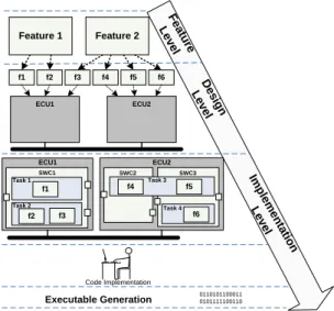
Apart from the modeling concepts, languages such as EAST-ADL2, AUTOSAR metamodel or AADL define implicitly or explicitly, methodology of design. In the context of the real-time systems its general characteristic is that of presented on Figure 1. At the Feature Level designer provides the specification of a system main features and requirements related to them. Next, designer progress to the Design Level by refining the previously specified features into the functions. The last can be either composite (can aggregate other functions) or atomic (non-concurrent entities). Additionally abstract hardware platform is provided at this stage, together with an allocation of functions into it. The main activities at the last, Implementation Level concern the transformation of the functional specification into the software architecture. The atomic functions are embedded within the software components and partitioned within the OS (Operating System) tasks. For the last, periods and priorities need to be defined. Finally, functions are implemented and hence executable for each microcontroller can be generated.
0110101100011 0101111100110 Executable Generation Feature 1 Feature 2 f1 f2 f3 f4 f5 f6 ECU1 ECU2 F ea tu re L ev e l D e s ign Le ve l Im p lem en ta tion L ev el Code Implementation SWC1 ECU1 Task 1 Task 2 ECU2 f1 f2 f3 SWC2 SWC3 f4 f5 f6 Task 3 Task 4
Figure 1: Methodology for Real-Time Systems Design
3.0 EARLY OPTIMIZATION OBJECTIVES
Throughout the overall design, system engineer has to make certain design decisions where most of them have a high impact on system functional as well as non-functional properties. Multitude of decisions to make and complexity of the system resulted in a wide range of algorithms and tools that support a designer. Most of them relate to the implementation level as their input in many cases is platform dependent and requires detailed information. However already at the design level certain design decisions have a tremendous influence on non-functional characteristics such as performance, cost and safety.
3.1 Safety
Specification of software/hardware architectures designed for the RTES often needs to prove its conformance to safety standard. Different types of standards exist for different kind of systems. For instance automotive OEMs (Original Equipment Manufacturer) have to follow the restrictions and suggestions of the ISO 26262 [9] safety standard. It imposes consideration of the safety aspect at the functional level. To comply with it, it is crucial to perform Preliminary Hazard Analysis (PHA) in order to reveal the possible effects and consequences of failures [10]. Multitude of techniques exists for the identification of hazards and their causes: FFA, HAZOP, FMEA, FTA, etc. Such analysis should be followed by the planning of necessary safety engineering tasks that will help to decrease the risk assessed with PHA. ISO 26262 provides recommendations on risk prevention or risk mitigation solutions to implement. According to it, safety architecture concept includes the redundancy for the elements. This is a common approach to mitigate the risk related to failures of safety critical functions. In principle after identification of safety critical
A Model-Based Approach for Real-Time Systems Architecture Exploration
5 - 4 STO-MP-IST-115
functions, designer has to provide redundancy level for them. Namely the maximal and the minimal number of replicas for safety critical functions should be specified.
Certain assumptions hold concerning the replication strategy. These are:
1. Active replication style is considered: in this case all the replicas process the same input.
2. Replicas are assumed to be deterministic: the result of a behavior execution depends only on replicas initial state and of the sequence of executions already performed.
3. Replicas behave independently and mechanisms should be provided to ensure that all replicas receive the inputs in the same order to keep consistent the state of replicas.
4. Failed components do not damage the system, and are not repaired.
3.2 Cost
The second optimization parameter is the monetary cost of the system. It is computed as a weighted sum of used hardware resources (BUS-es and ECUs) where weight expresses the price of a particular hardware component. This is an intuitive way to analyze the system cost which when specified this way, stays in conflict with a performance of a distributed system [11]. Cheaper components or usage of a smaller number of hardware resources increase the workload of other hardware elements. Naturally there might be other ways to express the overall cost. They can relate to the overall size of on-chip local memory [12], which optimization might cause the increase of a system timing responses [13]. Next, cost of a logical component (in our case system functions) might also be considered. Usually there is a relation between the cost of a component and its reliability, namely the higher the cost the higher the reliability of a component [14] [15].
3.3 Performance
The last objective is the performance characterized by the ECU and BUS utilization, i.e. workload. ECU utilization is computed based on the WCET (Worst Case Execution Time) values of the functions that are allocated on the ECU and their execution periods. Similarly, to compute BUS utilization for the event triggered bus such as a CAN (Controller Area Network) all the messages transmitted through this bus, together with their transmission time and period are considered. Period of a message is the same as a period of a function that sends the message.
4.0 SYSML/MARTE MODELING
Input for our analysis/optimization framework is stated by the SysML & UML4SysML/MARTE models. SysML is a general purpose modeling language for systems engineering applications. SysML as described in the specification is the combination of UML4SysML and the SysML profile. SyML is technology agnostic. Hence it fits well as a modeling language for a generic framework unlike the pure UML which is software oriented. MARTE is used to complement SysML in formal modeling of non-functional requirements and properties related to timing. It is also used to provide additional semantics to the SysML Blocks that enable to differentiate the hardware entities and specify their properties such as a BUS speed.
4.1 Functional Structure and Behavior Modeling
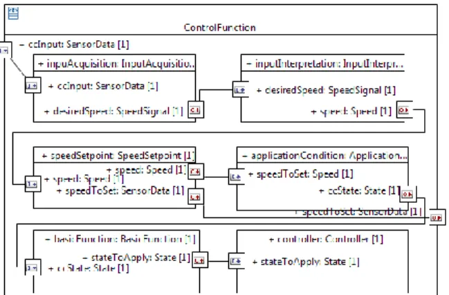
Modeling of a system functional structure within the framework is done with the SysML concept of the Block and UML4SysML Property, hence for this, Block and Internal Block Diagram are used (see Figure 2). The same applies to the modeling of a hardware architecture where hardware elements are typed with blocks stereotyped with the MARTE concepts such as HwComputingResource, HwBus, etc. Behavioral aspects are modeled with the UML4SysML Activity Diagrams. They depict control flows and events. Timing annotations of behavioral diagrams come from MARTE and serve to enrich the models with information about end-to-end deadlines, function time budgets and event periods (see Figure 3). Table 1 highlights the SysML/MARTE concepts used as an input for our analysis tool. Usage of these concepts
A Model-Based Approach for Real-Time Systems Architecture Exploration
STO-MP-IST-115 5 - 5
allows to reason about the utilization of an ECU and a BUS as well as about the monetary cost of the system based on the hardware platform specification.
Figure 2: Static specification of the Control Function on the Internal Block diagram
Figure 3: Behavioral models with timing specification
Table 1. Main modeling concepts used
Modeling Concept Purpose
SysML::Block Representation of a system functions and hardware elements. In addition, to differentiate between multiple hardware element types, MARTE annotations are used.
UML4SysML::Property Instances of functions/hardware elements UML4SysML::Port
UML4SysML::Interface UML4SysML::Operation
Modeling of a client server communication
SysML::FlowPort Modeling of a sender receiver communication
UML4SysML::AcceptEventAction Modeling of events triggering end to end flows MARTE::HwComputingResource ECU (Electronical Control Unit)
MARTE::HwSensorMARTE::HwActuator Sensors and actuators
MARTE::HwBus CAN or FlexRay bus
MARTE::SaStep Used to specify the worst case execution time needed for the timing analysis – property execTime
MARTE::GaWorkloadEvent Used to specify properties related to events (periodicity, period)
MARTE::SaEndToEndFlow Represents end-to-end flows and enables to specify end-to-end deadlines and store the results of a schedulability analysis
MARTE::Assign Used to map functions to hardware nodes
4.2 Redundancy Model
Taking into an account redundancy required to specify separate profile dedicated to express this concern. Neither SysML nor MARTE are sufficient enough to support this. Therefore our framework refers to the UML profile defined in our previous work [16] visible on the Figure 4.
A Model-Based Approach for Real-Time Systems Architecture Exploration
5 - 6 STO-MP-IST-115
The ReplicationStrategy stereotype allows the declaration of critical function prototypes to replicate. The properties of the aforementioned stereotype allow specifying the failure class (stereotype FailureClassKind), the replication style (ReplicationStyleKind), the initial number of replicas and the minimal number of replicas. As mentioned earlier our optimization algorithm considers for the moment only the active replica kind although profile differentiates more. Regarding the failure classes our profile focuses on three kinds:
• Arbitrary failures: a process is said to fail in an arbitrary manner if it deviates arbitrary from its specification.
• Omission failures: occurs when the process doesn’t send/receive a message that should be sent/received according to process specification.
• Crash failures: concerns situations in which process stops its execution prematurely.
In the optimization process, information about the replication strategy of certain functions is taken into an account in a following way. The function prototypes that are stereotyped with ReplicationStrategy are the candidates for the replication. This means that such function can be replicated in addition by the amount of
initialNumberReplicas – minimumNumberReplicas.
Figure 4: UML profile for Replication
5.0 EXPLORATION ALGORITHM
Exploration algorithm has been implemented within the Qompass framework. Following subsections describe it in more details.
5.1 Input for the Optimization
The input in its general form these are models based on the SysML, MARTE and replication profile, shown before. These models represent the system . The following information makes up the . This is a set of atomic functions where each function is characterized by its period and WCET (Worst Case Execution Time) . Following is set of function connections where connects functions
and . Each connection can add up to the BUS utilization if functions that it connects are allocated to different ECUs. In this case (of course if there is a BUS connecting the two ECUs) message will be sent over the BUS. Message is described by the time it is needed to transmit it. This time is computed based on a BUS speed and a message size . Message also has its period which in fact equals to the period of a function that sends it.
A Model-Based Approach for Real-Time Systems Architecture Exploration
STO-MP-IST-115 5 - 7
Next is a hardware platform which is a set of ECUs, and a set of BUS-es, . Each ECU is characterized by its speed factor and a set of BUS-es to which it connects . Speed factor is also a property of a BUS - .
Allocation of a function to the ECU is represented by the . In a similar way, allocation of messages is defined, .
Next these are the safety concerns. Each function for which replication strategy has been defined, can have a minimal number of replicas and initial number of replicas where . Replica
of a function is described as , where should hold. Functions for which replication strategy was defined belongs to the set . Final number of replicas used for is represented by the function . In addition to this, constraints on the utilization are considered. Utilization constraint for an ECU is defined as and . The same applies for the BUS - .
5.2 Problem Formulation
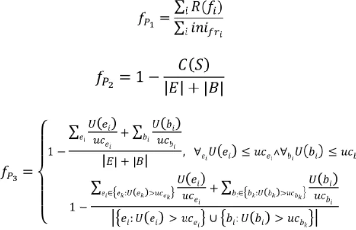
Given the input model, the problem formulation is to maximize the reliability (Problem P1), minimize the cost (Problem P2) and increase the system performance (Problem P3).
Problem P1
Problem P2
– cost of the system that equals to the number of used ECUs from the set plus the number of used BUS-es from the set . ECU is used if there is at least one function allocated to this ECU. BUS is used if there is at least one message exchanged through this bus.
Problem P3
is an ECU utilization which equals ∑
and ∑
5.3 Algorithm
Exploration algorithm is based on the genetic algorithms (GA). GA is an optimization technique patterned after natural selection in biological evolution. The general form of this algorithm is presented below. Algorithm 1 GA
1: Define crossover operator 2: Define mutation operator 3: Define fitness function 4: Encode the solution
5: Specify the size of an initial population -
6: Generate initial population
7: while(termination conditions are not met) 8: Evaluate each solution from the population
9: Generate new population by applying the crossover and mutation operators
10: end
A Model-Based Approach for Real-Time Systems Architecture Exploration
5 - 8 STO-MP-IST-115
In addition to this, our implementation always keeps the best solution. This means that if the best solution from the previous population is higher than the worst solution from the new one, the best solution will replace it. Also, for the termination condition we are simply choosing the number of iteartions.
Usage of GA requires defining few things that are specific to the optimization problem.
5.3.1 Encoding
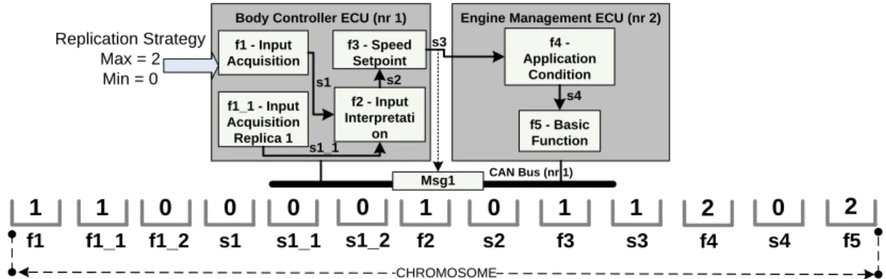
The first one is the encoding of each solution. Specific encoding is called a chromosome. In our case, encoding defines the allocation of each function to an ECU and each message to a BUS. Chromosomes can be represented as an array but in the final Java implementation we have used String object to define the chromosome which is a common way to proceed. The size of a chromosome is fixed, even if certain replicas or messages (sent to/from replicas) might not occur in the final implementation. To explain our encoding we refer to the example from the Figure 5. There are five functions: and possibility of at the most two more functions that are replicas for . Each cell in the chromosome corresponds either to a function or sent messages. Value in each cell is an integer number representing ECU (if cell corresponds to the function) or BUS (if cell corresponds to the message). Figure 5 shows an example of a valid chromosome. For instance function is allocated to the ECU with number 1 whereas was not allocated at all as the value is 0. Please note that the value equal to zero can be assigned only to the cells representing replicas and replica messages, as these functions are variable in terms of their final occurrence in the system. All the other functions have to be allocated somewhere. Chromosome is valid if the assignment of BUS-es to the messages corresponds to the allocation of functions into the ECUs. Namely if there is no intra-ECU communication between two functions (because they reside on the same ECU), message that is sent between them is not allocated to any of the BUS-es. Moreover if a redundant function is not allocated (lower level of redundancy) all the incoming and outgoing messages of this function are not allocated as well. Operations such as crossover and mutation might create an invalid chromosome and to avoid this we use simple correction mechanism. It iterates through the chromosome considering only the message cells. It checks whether the message should be allocated to any BUS or no. If it shouldn’t be, the chromosome cell is zeroed. If the message should be allocated on the BUS, but the value is either zero or corresponds to the BUS that doesn’t connect the ECUs on which functions exchanging the message were allocated, it will randomly choose a BUS that is correct.
Body Controller ECU (nr 1) Engine Management ECU (nr 2) f1 - Input Acquisition f2 - Input Interpretati on f3 - Speed Setpoint f4 - Application Condition f5 - Basic Function Msg1 CAN Bus (nr 1) Replication Strategy Max = 2 Min = 0 f1_1 - Input Acquisition Replica 1 f1 f1_1 s1 s1_1 f2 s2 f3 s3 1 1 0 0 1 0 1 1 CHROMOSOME s1 s1_1 s2 s3 s4 f4 2 s4 0 f5 2 s1_2 0 f1_2 0
Figure 5: Example of a valid chromosome
5.3.2 Crossover
An effective GA highly depends on a crossover operator. In general, it combines information from two parent chromosomes to create a new child. The choice of parent chromosomes can be done in many ways, but it is always highly dependent on a chromosome fitness rate. For our implementation we have chosen OX3 crossover operator [17] with a tournament selection. The OX3 picks two random points and to generate
A Model-Based Approach for Real-Time Systems Architecture Exploration
STO-MP-IST-115 5 - 9
a new chromosome, it takes the values between these points from one parent and copies them in the same absolute position to the new chromosome. The remaining values are inherited from the second parent, also in the same absolute position.
5.3.3 Mutation
Mutation operator chooses randomly a point of a new chromosome. The value at this point will be changed to the new random value. Of course if the randomly selected point corresponds to the function, new value will be chosen from the list of available ECUs. If this is a message, new value will be chosen from the list of available BUS-es.
5.3.4 Fitness Function
The fitness function defines how good a specific solution is, namely how much it optimizes the initial criteria. It is used to rank the chromosomes. Our fitness function is a weighted sum of three functions, each corresponding to the formulated problem, , , . Hence , where:
∑ ∑ | | | | { ∑ ∑ | | | | ∑ { } ∑ { } |{ } { }|
Function is defined for two different cases. The first one occurs if for all the ECUs and BUS-es, their utilization doesn’t exceed the specified constraint. The second case is used in case if there is at least one ECU or at least one BUS which utilization exceeds the constraint. In such situation, fitness function will try to penalize the configuration by drastically lowering the overall result of a fitness function.
6.0 USE CASE
We show here input models based on the SysML, MARTE and the replication profile, that state an input for the Qompass tool.
The first is a set of structural models which were modeled with the Internal Block Diagram of the SysML. These are shown on the figures: Figure 6, Figure 7, Figure 8. Please note that certain behaviour models were already introduced before (see Figure 3).
A Model-Based Approach for Real-Time Systems Architecture Exploration
5 - 10 STO-MP-IST-115
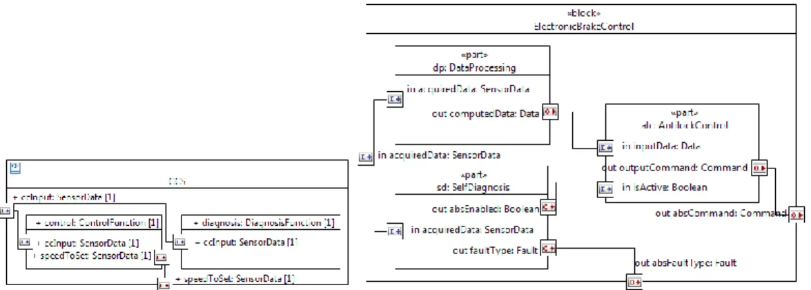
Figure 7: First level of decomposition of the CCS and ABS system
Figure 8: Decomposition of the Diagnosis Function and the Control Function with the definition of the Replication Strategy for the Diagnosis and the Controller Functions.
Second view on the system focuses on the hardware architecture. It defines the hardware types, such as ECU types or BUS types. In addition, it contains specification of hardware architecture, i.e. instances of a specific ECU or BUS types and the connections (see Figure 9).
A Model-Based Approach for Real-Time Systems Architecture Exploration
STO-MP-IST-115 5 - 11
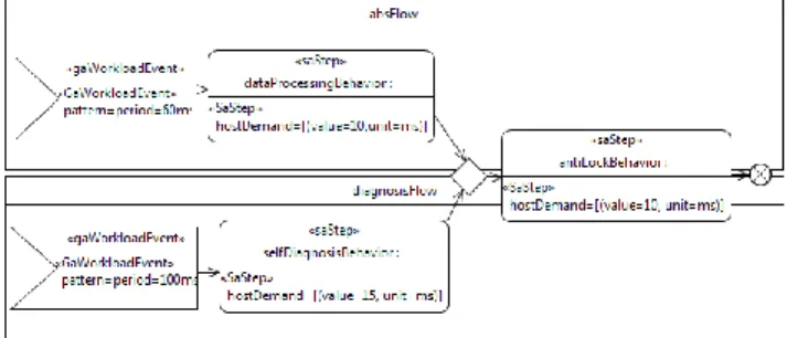
The third view on the system regards behavioral aspects and the timing information. Figure 10 presents the behavior of the Control Flow function. The behavior of the Diagnosis Function was already presented on the Figure 3, together with the first level of behavior specification for the ABS.
Figure 10: Behavior of a Control Function with timing annotations
Figure 11: Behavior of the ABS - two end-to-end flows
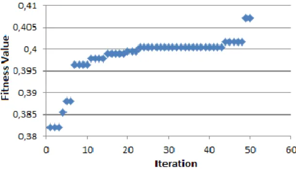
We run our test two times with a different weights for the functions , , . Test has been run on a population with a size of 100000. Number of iterations equaled 50.
Results are shown below. In addition Figure 12 presents the changes of the fitness value for the first case.
Table 2. Optimization results
BUS/ECU Utilization (%) Cost
Case 1 Case 2 Case 1 Case 2
ECU1 47.05 0 4 3 ECU2 0 0 ECU3 55.2 80.6 ECU4 87.96667 69.6 BUS1 0 0 BUS2 15.333335 12.666667
A Model-Based Approach for Real-Time Systems Architecture Exploration
5 - 12 STO-MP-IST-115
Figure 12: Changes of a Fitness Value throughout the iterations
Regarding the safety concern, for the first case, only function alc of type AntilockControl has been replicated with its maximal number of replicas, i.e. 2. Concerning the second scenario, it is interesting to note that as the weight for the safety function is zero, none of the functions were replicated, i.e. zero replicas were generated for them.
7.0 SUMMARY & CONCLUSIONS
This work presented a framework that can serve for the modeling, analysis and optimization of real-time cyber-physical systems. Its main contribution lies in combining SysML and MARTE to model functional and non-functional properties and more importantly, optimization of systems at the early development stage, i.e. at the functional level. The optimization metric expresses three objectives which relate to the system safety, performance and cost.
As a future work we are planning to further extend our framework with new optimization techniques that consider other objectives such as memory or end-to-end timing responses. Also, to enable the analysis and optimization of architectures expressed with languages other than SysML/MARTE we are developing set of transformations. For example we can generate a SysML/MARTE model out of an EAST-ADL2 model, and hence we can analyse and optimize automotive architectures.
REFERENCES
[1] ISO/IEC/(IEEE), “ISO/IEC/IEEE 42010:2011 : Systems and software engineering - Architecture description,” 11 2011.
[2] Unified Modeling Language Superstructure v2.3, OMG Std.
[3] OMG Systems Modeling Language (OMG SysML), Version 1.2, formal/2010-06-02, OMG, June 2010. [Online]. Available: http://www.omg.org/spec/SysML/1.2/
[4] UML Profile for MARTE: Modeling and Analysis of Real-Time Embedded Systems, Version 1.0,
formal/2009-11-02, OMG, November 2009. [Online]. Available: http://www.omgmarte.org/
[5] G. D. Feiler, P. and J. Hudak, The Architecture Analysis and Design Language(AADL): An
Introduction, Technical Note, CMU/SEI-2006-TN-011., June 2006.
[6] Advancing Traffic Efficiency and Safety through Software Technology phase 2 (ATESST2), Deliverable
D4.1.1, EAST-ADL Domain Model Specification, June 2010.
[7] S. Anssi, S. Tucci-Piergiovanni, S. Kuntz, S. Gerard, and F. Terrier, “Enabling scheduling analysis for autosar systems,” in Object/Component/Service-Oriented Real-Time Distributed Computing (ISORC),
2011 14th IEEE International Symposium on, march 2011, pp. 152 –159.
[8] C. Mraidha, S. Tucci-Piergiovanni, and S. Gerard, “Optimum: a marte-based methodology for schedulability analysis at early design stages,” SIGSOFT Softw. Eng. Notes, vol. 36, pp. 1–8, January 2011. [Online]. Available: http://doi.acm.org/10.1145/1921532.1921555
[9] International Standards Organization, ISO/DIS 26262:2009 - Draft International Standard Road
A Model-Based Approach for Real-Time Systems Architecture Exploration
STO-MP-IST-115 5 - 13
[10] A. Sandberg, D. Chen, H. Lönn, R. Johansson, L. Feng, M. Törngren, S. Torchiaro, R. Tavakoli-Kolagari, and A. Abele, “Model-based safety engineering of interdependent functions in automotive vehicles using east-adl2,” in Proceedings of the 29th international conference on Computer safety,
reliability, and security, ser. SAFECOMP’10. Berlin, Heidelberg: Springer-Verlag, 2010, pp. 332–346.
[Online]. Available: http://dl.acm.org/citation.cfm?id=1886301.1886335
[11] J. Balicki, “Tabu-based evolutionary algorithm with negative selection for pareto-optimization in distributed systems,” in Proceedings of the 7th WSEAS International Conference on Artificial
intelligence, knowledge engineering and data bases, ser. AIKED’08. Stevens Point, Wisconsin, USA:
World Scientific and Engineering Academy and Society (WSEAS), 2008, pp. 327–332. [Online]. Available: http://dl.acm.org/citation.cfm?id=1415881.1415933
[12] M. Ceriani, F. Ferrandi, P. L. Lanzi, D. Sciuto, and A. Tumeo, “Multiprocessor systems-on-chip synthesis using multi-objective evolutionary computation,” in Proceedings of the 12th annual
conference on Genetic and evolutionary computation, ser. GECCO ’10. New York, NY, USA: ACM,
2010, pp. 1267–1274. [Online]. Available: http://doi.acm.org/10.1145/1830483.1830710
[13] A. Ferrari, M. D. Natale, G. Gentile, G. Reggiani, and P. Gai, “Time and memory tradeoffs in the implementation of autosar components,” in DATE, 2009, pp. 864–869.
[14] D. W. Coit, I. S. Member, A. E. Smith, and I. Member, “Reliability optimization of series-parallel systems using a genetic algorithm,” IEEE Transactions on Reliability, vol. 45, pp. 254–260, 1996. [15] S. S. Gokhale, “Software application design based on architecture, reliability and cost,” in Proceedings
of the Ninth International Symposium on Computers and Communications 2004 Volume 2 (ISCC"04) - Volume 02, ser. ISCC ’04. Washington, DC, USA: IEEE Computer Society, 2004, pp. 1098–1103.
[Online]. Available: http://dl.acm.org/citation.cfm?id=1126253.1126657
[16] S. Tucci-Piergiovanni, C. Mraidha, E. Wozniak, A. Lanusse, and S. Gerard, “A uml model-based approach for replication assessment of autosar safety-critical applications,” IEEE TrustCom/IEEE
ICESS/FCST, International Joint Conference of, vol. 0, pp. 1176–1187, 2011.
A Model-Based Approach for Real-Time Systems Architecture Exploration
5 - 14 STO-MP-IST-115