HAL Id: in2p3-00168661
http://hal.in2p3.fr/in2p3-00168661
Submitted on 29 Aug 2007HAL is a multi-disciplinary open access archive for the deposit and dissemination of sci-entific research documents, whether they are pub-lished or not. The documents may come from teaching and research institutions in France or abroad, or from public or private research centers.
L’archive ouverte pluridisciplinaire HAL, est destinée au dépôt et à la diffusion de documents scientifiques de niveau recherche, publiés ou non, émanant des établissements d’enseignement et de recherche français ou étrangers, des laboratoires publics ou privés.
Technical challenges for head-on collisions and
extraction at the ILC
O. Napoly, O. Delferrière, M. Durante, J. Payet, C. Rippon, D. Uriot, B.
Balhan, J. Borburgh, B. Goddard, S. Kuroda, et al.
To cite this version:
O. Napoly, O. Delferrière, M. Durante, J. Payet, C. Rippon, et al.. Technical challenges for head-on collisions and extraction at the ILC. 22nd Particle Accelerator Conference 07 (PAC’07), Jun 2007, Albuquerque, United States. �in2p3-00168661�
TECHNICAL CHALLENGES FOR HEAD-ON COLLISIONS AND
EXTRACTION AT THE ILC *
O. Napoly#, O. Delferrière, M. Durante, J. Payet, C. Rippon, D. Uriot (CEA, Gif-sur-Yvette),
B. Balhan, J. Borburgh, B. Goddard (CERN, Geneva), S. Kuroda (KEK, Ibaraki), Y. Iwashita
(Kyoto ICR, Kyoto), M. del Carmen Alabau, P. Bambade, J. Brossard, O. Dadoun, C. Rimbault
(LAL, Orsay), G. Sabbi (LBNL, Berkeley, CA), L. Keller (SLAC, Menlo Park, CA), D.
Angal-Kalinin, F. Jackson, S. Tzenov (STFC/DL/ASTeC, Daresbury), R. Appleby (UMAN, Manchester)
Abstract
An interaction region with head-on collisions is considered as an alternative to the baseline ILC configuration. Progress in the final focus optics design includes engineered large bore superconducting final doublet magnets and their 3D magnetic integration in the detector solenoids. Progress on the beam separation optics is based on technical designs of electrostatic separator and special extraction quadrupoles. The spent beam extraction is realized by a staged collimation scheme relying on realistic collimators.
FINAL FOCUS OPTICS
Final focus system has been designed to fit into ILC Reference Design Report [1] length constraints and has been completely redesigned and optimised for various head-on final doublet parameters covering both 500 GeV and 1 TeV centre of mass parameter space. The design is available for l* ranging from 4.0-6.0 m. The optimisation concerns the final doublet (FD) region and the chromatic correction. Choosing l* to be 4 m and the FD magnets to be superconducting (SC) quadrupoles with 56 mm bore diameter and 250 T/m gradient, the short separation of 1.3m between FD provides enough space for a pair of SC sextupoles, correctors and instrumentation. The 28 m long electrostatic separator is positioned 2 m behind the FD package in order to accommodate the kickers needed for the IP fast feedback system.
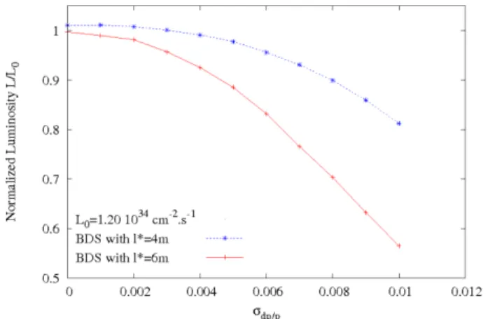
Figure 1: Final focus bandwidths for l*= 4 m and 6 m. The final focus system has a good bandwidth (Fig.1) for different parameter sets. Six sextupoles are used to correct
the chromaticity and compensate the aberrations: two SC sextupoles with 3T pole tip field at 28 mm radius are inserted in the final doublet, three others at the high beta upstream points, and one in the middle of the energy collimation section to improve the overall correction. The optimization of luminosity is done using LUMOPT [2]. At 500 GeV CM energy, the final doublet quadrupoles and sextupoles would be about 1 m long superconducting magnets using NbTi conductors, close to the LHC lattice or low-beta magnets. At 1 TeV CM energy, 50 % higher gradients would be required, accessible via the Nb3Sn conductor technology developed worldwide.
ELECTROSTATIC SEPARATOR
The first extraction stage uses electrostatic separators with ±131 kV across a 10 cm gap, following LEP experience [3]. There would be seven modules of 4 m long electrodes (Fig.2), each enclosed in an 8 mT dipole which provides half of the total 0.5 mrad bend in the outgoing beam and cancels the bend of the incoming beam. The Titanium electrodes would be split by a 5 cm gap in the horizontal plane to avoid direct beam losses.
Figure 2: Layout of electrostatic separators with split electrodes in the enlarged tunnel. The compensating dipole envelopes the separator.
With 26.2 kV/cm electrostatic field, this first stage provides 12 mm transverse separation at the first parasitic crossing 55 m from the IP and the separation is 7cm at QD2A. First electrostatic separator starts at 11.3 m from the IP. The effect of parasitic crossings coupled to the IP kink instability on the stability of the collision has been calculated [5]. A study done for a fixed offset confirms that 8 mm is the minimum necessary separation to stabilize the collisions.
_________________________________________
*Work supported by the EC under the FP6 “Research Infrasctructure Action - Structuring the European Research Area” EUROTeV DS Project Contract no.011899 RIDS
THPMN005 Proceedings of PAC07, Albuquerque, New Mexico, USA
03 Linear Colliders, Lepton Accelerators and New Acceleration Techniques
2716
A03 Linear Colliders
Figure 3: Electrostatic separator high voltage circuit. The high voltage circuit for the seven separators (Fig.3) will be arranged using 4 generators per polarity for the tanks, a cost effective solution which decouples the separator modules by pairs to avoid sparking in chain. The corresponding dipoles should allow for the same degree of freedom. If needed to avoid particle showers on the last separator it would be possible to increase the field strength seen by the beam by using flat electrodes for the 1st two separators (efficiency 100%, instead of 84%) and opening the gap on the 7th separator. To obtain the same total required deflection, the applied voltages would remain the same.
EXTRACTION LINE
After the first bend from the electrostatic separators, the outgoing beam passes to the outside of the final focus soft bend magnets, and off-axis through the horizontally defocusing quadrupole QD2A (Fig. 4). This gives the outgoing beam the second part of the beam-separating bend with an outward kick of 1.8 mrad. The extraction line optics presented in [4] requires long extraction line. The need to make the beam parallel to the IP at the second focus for the polarization measurements introduces significant constraints on the layout of the extraction line. Due to overfocussing of low energy particles, very few charged particles lie within small spot size required at the second IP for polarimetry. Introducing large number of bends also increase the losses due to synchrotron radiation and cost of the beam line. For economical reasons, the downstream diagnostics has been removed from the extraction line optics. Alternative ideas about post-collision energy and polarization measurements are being considered to carry out these measurements very close to the IP.
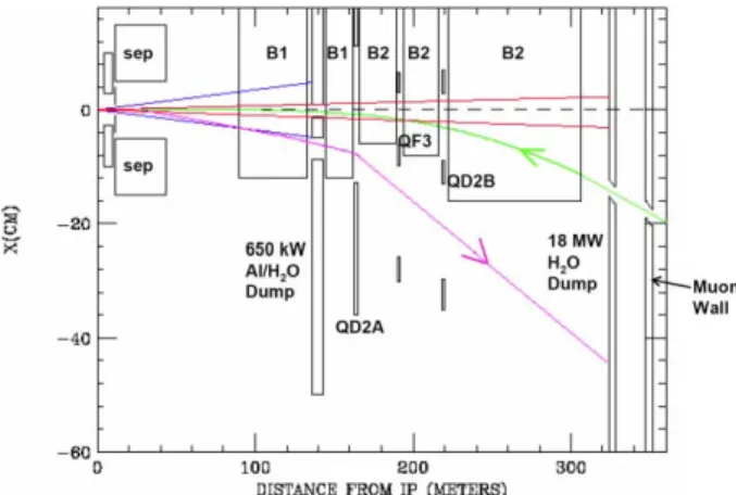
Figure 4: Plan view of zero degree extraction from IP to charged and photon beam dump.
The magnet QD2A is a conventional large-bore quadrupole, and the double aperture magnets QF3 and
QD2B are modelled after Q2 in the PEPII interaction region.
COLLIMATION AND DUMPS
The collimation system proposed here has a single high power dump at a location where much of the disrupted beam and beamstrahlung tails can be collimated, leaving the need for only a few lower power collimators in the rest of the extraction line. In addition, the high power beamstrahlung cone is going back through the incoming beam line and the beamstrahlung tails must be collimated in order to limit the shared magnet apertures to a reasonable size. In the present design, sufficient separation of the incoming beam and the outgoing beamstrahlung occurs at about 300 m from the IP.
As seen in Table 1, most of the collimation occurs at a single location, called the Intermediate Dump (Fig.5). This collimator, which has holes for the incoming and outgoing beams, would be modelled after a similar aluminum/water 2.2 MW device at SLAC and located at a place where it can be well shielded to protect the environment and nearby beam line elements from radiation damage. A collimator inboard of B1 and the Intermediate Dump must also be able to withstand temporary larger charged and beamstrahlung losses, given by the second set of power levels, when the beam-beam vertical deflection is at a maximum. A beam rastering system, similar to the baseline design, is also needed to prevent an undisrupted beam from damaging the main charged beam dump.
Table 1: Power lost at different locations for Nominal and Low Power parameter sets.
Power lost (kW) @ 500 GeV CM Nominal / Low P parameter set
Charged/Beamstrahlung Loss point Head-on Vertical offset Bhabhas QD0/SD0 0 / 0 0 / 0 1.5E-5 QF1/SF1 0 / 0.001 0 / 2.0E-04 2.5E-5
Synch. Mask 0 / 0.0023 0 / 0.0011 5.5E-5
Intermediate Dump 75 / 415 140 / 215 90/539 240/416 -Main Dump 10,160/ 4,500 125/115 10,030/4,200 135/95 -
Table 2: Power lost at the electrostatic separators for Nominal and High Luminosity parameter sets.
E.S. losses Power lost (W) @ 500 GeV CM
Nominal / High Lumi parameter set
Full electrodes Split electrodes
Beam 12.1 / 6 583 0.0 / 97.0 Bhabhas 0.92 / 2.0 0.019 / 0.063
Beam losses on separators
The total charged particle loss on the 7 extraction electrodes is summarized in Table 2. Full electrodes
Proceedings of PAC07, Albuquerque, New Mexico, USA THPMN005
03 Linear Colliders, Lepton Accelerators and New Acceleration Techniques
1-4244-0917-9/07/$25.00 c 2007 IEEE
A03 Linear Colliders
would presumably not sustain the kW power levels in the case of the High Luminosity parameter set. While the 5 cm split electrodes are significantly less exposed, the particles passing through the gaps are lost in the separator tank which needs to be grounded. To demonstrate that the beam losses are manageable, at least in the case of the nominal parameters, without raising the sparking rate to an unacceptable level requires an experimental study: a LEP separator module with full electrodes could be operated for this purpose in an electron beam line.
Figure 5: Beam holes through intermediate beam dump. The septum region between the two beams would have a design similar to the SLAC 2.2 MW energy slit.
Electrostatic Separator Failures
The handling of separator failures is of primary importance in the detector region. Although electrically decoupled, a stray beam could provoke a complete breakdown of the 7 separator array. In such a case, the incoming beam would not impact the detector region (Fig.6) and would only be stopped by the intermediate dump. In the less dramatic event of module failures by pairs, the beam trajectories are safely passing through the spent beam hole of the intermediate dump [6].
Figure 6: Beam trajectories and envelopes in case of full separator failures upstream and/or downstream of the IP. Notice that the synchrotron radiation mask is needed only in the other horizontal half-plane.
DETECTOR PUSH-PULL
The ideal scheme for the detector push-pull is to remove completely the final doublet quadrupoles from the
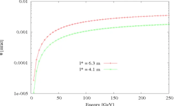
detector volume. Here we assume that this can be realized with l*=6.3 m. This raises two major difficulties related to the larger beta-functions and beam sizes in the quadrupole apertures: the chromaticity correction is expected to be less efficient (Fig.1), and the aperture of the final doublet needs to be increased. Using FD quadrupole of 130 mm bore diameter and 150 T/m field gradient, as contemplated for the LHC luminosity upgrade, the FD angular acceptance (Fig. 7) to low energy particles, is actually increased by a factor two for l*=6.3 m. An additional advantage of the long l* is that the solenoid coupling induces only 10% increase of the vertical IP spot size, due to the non-zero dispersion through the IR, which is easily tuned out. This study supports the feasibility of this scheme but it needs to be completed in more details.
Figure 7: Final doublet angular acceptance for low energy electrons originating from the IP.
OUTLOOK
Taking advantage of the long intra-bunch spacing, the head-on collision scheme offers an elegant, i.e. hardware economical, solution for the beam focusing and colliding. This is compensated by the challenges in the spent beam extraction posed by the final doublet overfocussing and the dispersion induced by the needed separation. These challenges do not appear to be insurmountable and technical solutions have been proposed which needs to be deepened and tested experimentally.
REFERENCES
[1] ILC Reference Design Report, ILC-2007-01
[2] J. Payet et al, “Automatic luminosity optimisation of the ILC head-on beam delivery system”, these proceedings
[3] B. Balhan et al, “Engineering Considerations for the Proposed Beam Extraction System at TESLA”, CERN Preprint SL-Note-2000-002
[4] O. Napoly et al,
“
Design of an interaction region with head-on collisions for the ILC”, Proceedings of EPAC2006, Edinburgh[5] J. Brossard et al, “Evaluation of luminosity reduction in the ILC head-on scheme from parasitic collisions”, these proceedings
[6] J. Payet, “Note on electrostatic separator failure”, to be published.
THPMN005 Proceedings of PAC07, Albuquerque, New Mexico, USA
03 Linear Colliders, Lepton Accelerators and New Acceleration Techniques
2718
A03 Linear Colliders