HAL Id: hal-01790290
https://hal.archives-ouvertes.fr/hal-01790290
Submitted on 11 May 2018
HAL is a multi-disciplinary open access
archive for the deposit and dissemination of
sci-entific research documents, whether they are
pub-lished or not. The documents may come from
teaching and research institutions in France or
abroad, or from public or private research centers.
L’archive ouverte pluridisciplinaire HAL, est
destinée au dépôt et à la diffusion de documents
scientifiques de niveau recherche, publiés ou non,
émanant des établissements d’enseignement et de
recherche français ou étrangers, des laboratoires
publics ou privés.
Reduction of the association phase of a ZigBee wireless
sensor network
Nancy Rachkidy, Alexandre Guitton, Michel Misson
To cite this version:
Nancy Rachkidy, Alexandre Guitton, Michel Misson. Reduction of the association phase of a ZigBee
wireless sensor network. Wireless autonomous devices, 2012. �hal-01790290�
Reduction of the association phase of a ZigBee wireless
sensor network
Nancy El Rachkidy, Alexandre Guitton, Michel Misson
ABSTRACT
Wireless Sensor Networks (WSNs) are increasingly used for monitoring applications in order to sense critical events in the environment. When a WSN is deployed (or when it restarts due to a software update), each node of the network has to perform an association procedure before being allowed to transmit data. Thus, it is crucial to re-duce the time required to have a fully-operational network, which is the time required for all the nodes to be associated. In this chapter, we describe a mechanism that en-ables nodes to initiate their association procedure at the right time, rather than when they are deployed. The mechanism is distributed and does not make any assumption on the underlying topology. We evaluate our mechanism on several random network deployments, as a function of the duty cycle and of the number of nodes. Extensive simulations show that our mechanism is able to improve the association phase by sig-nificantly reducing its duration, and by increasing the number of nodes that can be associated in a given duration.
INTRODUCTION
With the growth of monitoring applications, wireless sensor networks (WSNs) are becoming increasingly used. Most WSNs are composed of cheap battery-powered devices that are able to sense the environment and to communicate with each other in a wireless manner. WSNs have been used for wildlife tracking (Juang et al., 2002) and monitoring (He et al., 2004). In order to save enough energy to last for years with the current battery technology, low-power protocols are developed. The IEEE 802.15.4/ZigBee stack (IEEE 802.15, 2006; ZigBee, 2008) is a typical example for such networks.
Before monitoring data can be exchanged in the WSN, the network topology has to be discovered by the network protocols. This occurs during an initial phase, called the association phase, of the network. In this paper, we focus on the association phase rather than on the data exchange phase.
The association phase is often disregarded as it is assumed to occur only once, at the moment of deployment. However, we believe that the duration of the association phase is a major issue that has to be addressed. For example, when a network topol-ogy has to be deployed rapidly in order to monitor an emergency situation (after a building collapse or during a military operation), the duration of the association phase is crucial as the network is expected to be operational rapidly. Another example is when all the devices of a network reboot simultaneously (due to a software update), the association duration has to be reduced. Lastly, when a node fails, an important part of the network topology can be temporarily disconnected (until a new topology is built): all the disconnected nodes might try to re-associate themselves simultaneously, and the faster they can do it, the better.
In this chapter, we propose a mechanism that aims to reduce the duration of the associ-ation phase (that is, the time required for all nodes to be associated). Furthermore, we plan to increase the number of nodes that IEEE 802.15.4/ZigBee is able to associate in a reasonable time. Our mechanism delays the initiation of the association procedure of nodes until some of their neighbors are likely to be associated.
The remainder of this chapter is organized as follows. We describe briefly IEEE 802.15.4/ZigBee, and we focus on its association procedure. Then, we present related works on the duration of the association phase. Then, we describe our solution, called Automatic Triggering of Association (ATA), and show how it can be implemented and we apply our solution on random topologies and we show the gain of ATA compared to the basic mechanism used in IEEE 802.15.4/ZigBee. Finally, we conclude our work and give some perspectives.
STATE OF THE ART
In this section, we first give a brief overview of IEEE 802.15.4/ZigBee stack. Then, we describe its association procedure. Finally, we present papers that are related to the evaluation of the association duration of a WSN.
IEEE 802.15.4 and ZigBee standards
The IEEE 802.15.4 standard (IEEE 802.15, 2006) and the ZigBee standard (ZigBee, 2008) are currently the main standards in WSNs. These standards allow to intercon-nect sensors and actuators in order to monitor a physical environment (Zheng and Lee, 2004; Callaway et al., 2002).
The IEEE 802.15.4 standard defines the physical (PHY) and medium access control (MAC) layers of a low-rate wireless personal area network (LR-WPAN). The PHY layer operates on several frequency bands, including the industrial, scientific, and medical (ISM) band at2.4 GHz. The MAC layer uses a carrier-sense multiple
ac-cess with collision avoidance (CSMA/CA) mechanism in order to acac-cess the medium. The standard supports two types of topologies: the star topology and the mesh topol-ogy. The star topology is composed of one central node, called PAN coordinator, and several end-devices. The end-devices communicate with each other via the PAN co-ordinator. The PAN coordinator manages the associations of the end-devices to the network. The network size is thus limited to the communication range of the devices. The mesh topology is composed of three types of nodes: the PAN coordinator, the co-ordinators, and the end-devices. Each coordinator can communicate with any device within its communication range, while the end-devices can only communicate with their parent coordinator. In the mesh topology, the network size is not limited to the communication range, but the establishment of the topology is more complicated. The ZigBee standard (ZigBee, 2008) defines the upper layers of a LP-WPAN and assumes that lower layers are compliant with IEEE 80.15.4. The ZigBee standard uses the same type of devices as IEEE 802.15.4, and defines three topologies: the star topology, the mesh topology, and the tree topology. In the tree topology, the PAN coordinator initiates the tree construction. It considers itself as the root of the tree. The coordinators and end-devices that try to join the network have to be associated to coordinators that are already associated to the tree, by using parent-child relationships: a coordinator can have several child but only one parent. In this chapter, we focus on the tree topology.
The MAC layer of IEEE 802.15.4 has two operational modes: beacon-enabled and non beacon-enabled mode. In the beacon-enabled mode, each coordinator period-ically sends beacons. Beacons contain information about the structure of a cycle, called superframe. This superframe is composed of two periods: an activity period, where the slotted CSMA/CA algorithm is used, and an inactivity period. In the non beacon-enabled mode, the coordinators do not send beacons periodically. Competi-tion to access the medium is solved using the unslotted CSMA/CA algorithm, a slight variation of the slotted CSMA/CA algorithm. In this chapter, we focus on the beacon-enabled mode, which is the mode that allows the highest energy savings.
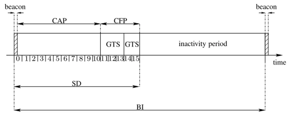
Structure of the superframe in the beacon-enabled mode A superframe is limited by the transmission (or the reception) of a beacon and it is composed of an activity period and of an inactivity period. All the devices that are under the supervision of a coordinator are synchronized by the beacon they have received, and they all share the same activity period. All the devices can switch to sleep mode when the inactivity period begins.
The activity period is divided into two periods: the contention access period, called CAP, and the contention free period, called CFP. CAP defines a time interval during which all the nodes are in competition in order to access the medium (using slotted CSMA/CA). The CAP is divided into sixteen equal time slots. The CFP is optional: when it exists, it guarantees the access to the medium by reserving time slots (denoted
by GTS, for guaranteed time slots) for each device-coordinator pair. Figure1. Superframe structure.
0 0 0 1 1 1 0 0 0 1 1 1 beacon beacon CAP CFP GTS GTS inactivity period SD BI 0 1 2 3 4 5 6 7 8 9 101112131415 time
Figure 1 illustrates the different periods of the superframe. The periodicity of the bea-cons, denoted by the beacon interval (BI), is a function of a parameter called beacon order (BO), which is specified by the PAN coordinator and transmitted in every bea-con frame. The duration of the activity period, denoted by the superframe duration (SD), is determined by a parameter called superframe order (SO). The values of BI and SD are given by the following equations.
(
BI= aBaseSuperf rameDuration · 2BO,
SD= aBaseSuperf rameDuration · 2SO,
with0 ≤ SO ≤ BO ≤ 14. aBaseSuperframeDuration is equal to 15.36 ms. SO and BO define the duty cycle of the nodes. Note that when SO is equal to BO, the superframe does not contain an inactivity period and the nodes are always active.
Association procedure of IEEE 802.15.4/ZigBee
The association procedure is the mechanism used by a new node (both coordinators and end-devices) to join the network. In the beacon-enabled mode, a node performs a passive scan (neighbor discovery), which consists in listening for beacons sent by neighboring coordinators. If no suitable coordinator is found, the device switches to an active scan, which consists in broadcasting beacon requests. When a suitable coordinator is found, the new node sends an association request to the coordinator. The coordinator answers with an association response.
The association procedure might fail due to two main reasons: (1) when no active co-ordinator is detected in range and (2) when the access to the channel is unsuccessful. These reasons are linked to the channel load, as a high channel load reduces the proba-bility to succeed in accessing the channel and increases the probaproba-bility to lose frames,
which in turn reduces the probability to detect a coordinator in range. The main prob-lem of the association procedure of IEEE 802.15.4/ZigBee is that in an overloaded network, unassociated devices keep sending beacon requests or association requests, which keeps the load of the network high.
Related works
In (Abbagnale et al., 2009), the authors study the percentage of nodes that are able to connect to the network, when there are several mobile PAN coordinators. The authors state that when PAN coordinators move simultaneously, the percentage of connected sensor nodes is lower than when the PAN coordinators move sequentially. They also show that the non beacon-enabled mode is more efficient in terms of association du-ration and energy consumption for end-devices than the beacon-enabled mode. How-ever, they do not consider the energy spent by coordinators (which cannot sleep in the non beacon-enabled mode), and do not evaluate the association duration required for the whole network.
In our previous work (El Rachkidy et al., 2009), we have proposed the SNAIL mech-anism to reduce the association duration in a linear WSN. SNAIL (Sequential Node Activation In a Linear network) is a mechanism that activates nodes sequentially. In the SNAIL mechanism, the PAN coordinator is activated at timet0, and any other
noden ≥ 1 is activated at time tn = t0+ p + α(n − 1), where p denotes the
du-ration for the PAN coordinator to start andα denotes the average time required for a node to be associated to its predecessor. We estimated by simulations the value of p, which is approximately equal to 1 second. The value of α depends mainly on the value of BO (in the beacon-enabled mode), which is consistent with the fact that the congestion zone is moving from the PAN coordinator to the last associated node (Jun and Sichitiu, 2003). The main problem of the SNAIL mechanism is that it requires a linear topology.
In (El Rachkidy et al., 2009), we also proposed the Bull’s Eye mechanism (BEM) to reduce the association duration in a grid WSN. BEM activates simultaneously all the nodes at a given distance from the PAN coordinator. In BEM, the activation time of a noden at depth d is tn= t0+ p + βd, where β is the interval between the activation
of two successive depths. β does not depend on d as for large values of d, nodes are spaced out and BEM benefits from the parallelism of simultaneous associations. The main problems of BEM are that it requires a grid topology, and that the distance to the PAN coordinator has to be known for each node before the actual association.
PROPOSITION
In this section, we describe the main problems of the association phase of IEEE 802.15.4/ZigBee. Then, we describe the concepts of our solution, and some technical
details on how this solution can be implemented. Finally, we give a short discussion on our proposition.
Problems of the association phase
The association phase is the time required between the network deployment and the moment when the network is operational. The association phase is often ignored, as time constraints are unlikely shortly after the deployment. However, we believe that the duration of the association phase is important in many cases. For instance, when a network is deployed in an emergency scenario, or when all the devices of a network reboot after a software upgrade: the faster the network can become operational again, the better. Another example is when the protocol is evaluated through simulations, the necessary association phase delays the rest of the simulation.
Unfortunately, the association phase of IEEE 802.15.4/ZigBee is not specifically opti-mized. As soon as an IEEE/ZigBee device is switched on, it starts sending beacon re-quests. When several devices are switched in a short time interval, they all send these beacon requests, in addition to other control messages (such as association requests and association responses) or data messages. This large number of messages increases the number of collisions, which in turn increases the congestion on the medium and the duration of the association phase. It is even possible to have a situation where the nodes are unable to associate to the network, due to the constant overload produced by the control messages.
How to shorten the association phase?
The main cause of delay in the association phase is when several devices in range try to get associated to the network simultaneously. Although the slotted CSMA/CA protocol used in IEEE 802.15.4/ZigBee introduces backoffs to reduce congestion, it is not sufficient when the load of the control traffic is too high (this is a general weakness of CSMA/CA protocols under large network load). Moreover, the production of as-sociation messages does not depend on the congestion of the network: when a device is trying to associate to the network, it produces a constant traffic load. A solution to this problem is to activate devices at different instants, rather than all at the same time. Ideally, devices have to be activated depending on the topology. Devices close to the PAN coordinator should be activated before devices far from the PAN coordinator, as the latter cannot be associated to the network before the former. In other words, devices should be activated depending on their distance to the PAN coordinator. This is an issue, however, as the distance to the PAN coordinator is not known by devices before the association: there is a need of a mechanism that infers the distance to the PAN coordinator.
To infer the distanced from a node n to the PAN coordinator, we use the overhearing capability of noden. The node n does not start the association phase until it overhears specific frames on the channel. When this happens,n assumes that it has at least one neighbor n′ which is being associated. n can also determine that it is at distance
d ≤ d′+ 1 of the PAN coordinator, where d′is the distance from noden′to the PAN
coordinator. Then,n starts its association phase after a delay δ(d), to give n′(and
possibly, other neighbors) enough time to complete the association procedure. We decided to compute the delayδ(d) according to the following recursive function: δ(0) = 0, δ(d) = δ(d′) + γ.f (d), where γ is a constant, n′is the first node thatn
detected,d′is the depth ofn′, andf is a function that approximates the number of
nodes in range ofn and at distance d of the PAN coordinator. The rationale behind this functionδ is to have all nodes at distance d′associated first, before nodes at distanced
start their own association (withd′< d). Additionally, the design of δ(d) relies on the
fact that several nodes at the same depthd can be activated at the same time, provided that they are distant enough. Even if the number of nodes at distanced increases with d, it is probable that the number of nodes in range of n does not increase beyond a certain point.
Technical aspects of our solution
In this subsection, we describe three technical aspects of our solution:
• how each node can estimate its own distanced to the PAN coordinator prior to the association,
• how each node can compute the time where it starts its own association, • what are the required changes in the IEEE 802.15.4/ZigBee stack.
To determine the distanced to a PAN coordinator by overhearing messages, we use the following three rules. Rule 1: the PAN coordinator knows that its own distance is 0. Rule 2: when a node overhears a beacon message from the PAN coordinator itself, it knows that its distance is 1. Note that a node can determine whether a beacon message is sent by the PAN coordinator by checking if the source address of the beacon frame is 0 or not. Rule 3: when a node overhears an association request message from a noden′, it can obtain the short address of the father ofn′ (which
is the destination of the association request frame). Using properties of the IEEE 802.15.4/ZigBee hierarchical addressing,n can compute the depth d′′of the father
n′′ofn′, and in turn assumes that its own distanced is d′′+ 2. Note that it might not
be possible for noden to overhear the association response of n′′directly, however.
Figure 2 displays a simple topology to illustrate Rules 2 and 3. When the PAN coor-dinatorp starts sending beacons (message 1), they are overheard by n1, which applies
association procedure. After a while,n1 sends its association request (message 2),
which is received byp and overheard by n2. p sends an association response to n1
(which might not be received byn2), which completes the association procedure of
n1. In parallel,n2applies Rule 3 and delays its association untilt2. Whent2expires,
n2 initiates its association procedure. After a while,n2sends its association request
(message 3), which is received byn1 and overheard byn3. n1sends an association
response ton2, which completes the association procedure ofn2, whilen3 applies
Rule 3 and delays its association untilt3. The procedure is repeated for all the other
nodes in the network.
Figure2. Beacons received directly from the PAN coordinator and association requests can be used to estimate the distanced to the PAN coordinator.
3 2 1 2 3 p n1 n2 n3
Let us denote bytstart(d) (and respectively tend(d)) the expected starting (resp. end-ing) time of the first (resp. last) node at distanced. Our aim is to have tstart(d + 1) = tend(d) and tend(d) = tstart(d)+δ(d). Now, we define the starting time tstart(n, d) of an arbitrary noden at distance d by tstart(n, d) = treception(n′, n) + δ(d′) + r,
where treception(n′, n) is the time when n detected the first activity of n′, and
r is a random variable used to avoid having all the nodes at depth d activate at the same time. By replacing δ(d′) with its expression, we have: tstart(n, d) =
treception(n′, n) + γ.f (d′) + r.
Figure 3 depicts a grid topology with a PAN coordinator denoted byp. This topol-ogy is used solely to explain our mechanism on a simple topoltopol-ogy but ATA does not require the topology to be uniform. Nodes at distanced1andd2are shown using a
dotted line. The communication range of two nodes,n1 (at distance d1) andn2 (at
distanced2), is shown using a circle. Noden1has four neighbors that are at distance
d1. Noden2, further away from the PAN coordinator, has only two neighbors that
are at distanced2. Thus, functionf should be designed so that when d is small, it is
likely that several nodes at distanced are in range of each other. Oppositely, when d is large, it is likely that few nodes at distanced are in range. We use the following definition:f (d) = 1 + 1/(d + 1).
From an implementation point of view, the required changes are limited. The main issue is to separate the booting of the device and the beginning of the association procedure. When a device is booting, it should start listening to frames. Once a frame that match one of the criteria (either Rule 2 or Rule 3) is received, a delay is computed and the association procedure is started after this delay.
Figure3. When the distanced to the PAN coordinator (denoted by p) is small, many nodes at distanced are in range of each other. When d is large, few nodes at distance d are in range of each other.
p nodes at distanced1 nodes at distanced2 n1 n2 Discussion
Our solution aims at reducing the number of control messages generated by IEEE 802.15.4/ZigBee during the association phase, as nodes do not start sending beacon requests or association requests until one of their neighbors is a candidate (i.e., one of their neighbor has started its association procedure).
Our algorithm is not optimal, as it makes several approximations: the distance to the PAN coordinator computed by each node might not be the shortest distance, the num-ber of neighbors having the same distance to the PAN coordinator is approximated (as functionf assumes an uniform density and a large topology). However, our algo-rithm has the following strengths: it does not require any additional control messages, it does not have any requirement on the topology, it is robust to any error in the ap-proximations (although the performance improvement might be reduced when errors are made), and it avoids overloading the network with useless control traffic.
SIMULATION RESULTS
In this section, we describe our simulation results on the performance of ATA by comparing it with IEEE 802.15.4/ZigBee. We describe first the parameter settings we
used in our simulations. Then, we detail the performance results according to each metric.
Parameter settings
We used the NS-2 simulator (version 2.31) for the simulations, with IEEE 802.15.4 beacon-enabled mode. In order to have consistent results, results are averaged over 100 repetitions. In the simulations, we focused on random (connected) topologies, where all devices are coordinators. The PAN coordinator is chosen at the center of the network. We varied the number of nodes and the duty cycle of nodes (through vari-ables BO and SO). We stopped the simulations as soon as all devices were associated (or after 2000 seconds).
Performance metrics
We used two performance metrics: the percentage of associated nodes, and the du-ration of the association phase. The percentage of associated nodes is defined as the total number of associated nodes after 2000 seconds, divided by the total number of nodes. The duration of the association phase is the time required for the last node to be associated (when all nodes are associated). Thus, the duration of the association phase only takes into account the simulations where all the nodes were associated successfully.
For each metric, we compare the IEEE 802.15.4/ZigBee approach (referred to as the basic approach) with our ATA mechanism, with varying values ofγ. Recall that γ models the expected time (in seconds) required to associate a node.
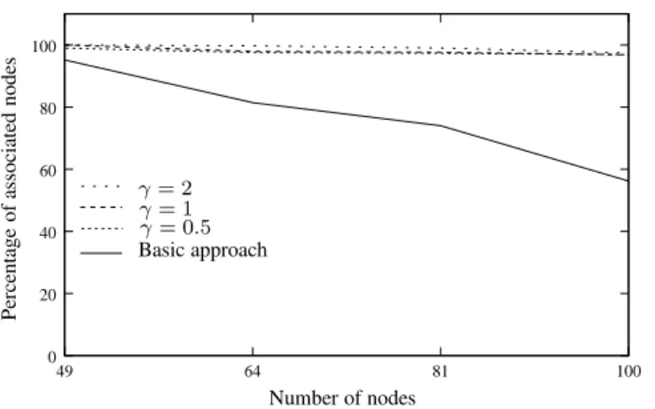
Percentage of associated nodes Figure 4 shows the percentage of associated nodes as a function of the total number of nodes, for a fixed value of BO=SO=5 (with these settings, nodes do not switch to sleep mode), and for three values ofγ. When BO is grater than 5, nodes cannot be associated using the basic approach. With the basic approach, the percentage of associated nodes decreases when the number of nodes increases. Indeed, when a large number of nodes try to be associated to the network, the control traffic becomes high, and it is more difficult for nodes to succeed in their association. For a network composed of 49 nodes, about 95% of the nodes can be associated to the network. This percentage decreases down to 58% for a network size of 100 nodes. We can see that ATA outperforms the basic approach for all the values ofγ, and is able to achieve a percentage of nearly 100% associated nodes. ATA reduces the traffic load by activating nodes when at least one neighbor is being associated, rather than at the beginning of the simulation. The value ofγ has a limited impact on the percentage of associated nodes.
Figure4. ATA outperforms the basic approach in terms of percentage of associated nodes, when BO=SO=5.
0 20 40 60 80 100 49 64 81 100 P er ce n ta g e o f as so ci at ed n o d es Number of nodes Basic approach γ = 1 γ = 2 γ = 0.5
Figure 5 illustrates the percentage of associated nodes in the network as a function of BO, with BO=SO (that is, there is no inactivity period), for a network size of 100 nodes. In the basic approach, it is easier for nodes to be associated to the net-work, as beacons are transmitted more often by coordinators. When BO increases, nodes require more control messages to find a suitable parent coordinator. The ATA mechanism shows a better behavior than the basic approach. For example, when BO=SO=3, only 85% of the nodes were associated with the basic approach, while nearly 100% of the nodes were associated with ATA. The improvement is even larger when BO=SO=7, where the basic approach was able to associate only 52% of the nodes, while ATA was able to associate more than 90% (the actual value depending onγ). This gain can also be explained by the fact that ATA reduces the control over-head. Again, the actual design of functionf , described in Sect. , and the choice of γ, play a secondary role for this metric.
Figure5. The gain of ATA compared to the basic approach reaches 48%.
0 20 40 60 80 100 3 4 5 6 7 P er ce n ta g e o f as so ci at ed n o d es Value of BO and SO Basic approach γ = 0.5 γ = 1 γ = 2
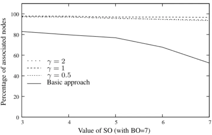
Figure 6 shows the percentage of nodes that are associated as a function of SO, for a network size of 100 nodes and for BO=7. Recall that SO is used to define the duty cycle: the duty cycle is 100% when SO=BO, 50% when SO=BO-1, 25% when SO=BO-2, and so on. With the basic approach, the percentage of associated nodes decreases when the value of SO increases. This can be explained by the fact that when SO is large, the duty cycle of nodes is large, and they send a large number of control messages. Reducing the opportunity for nodes to transmit more messages favors the basic approach. ATA is able to maintain a very high percentage of associated nodes, for all the values of SO. When SO=3, the basic approach is able to associate 82% of the nodes, while ATA is able to associate 97% of the nodes. When SO=7, the basic approach is able to associate 52% of the nodes while ATA is able to associate more than 90% of the nodes.
Figure6. ATA significantly increases the percentage of associated nodes in the net-work. 0 20 40 60 80 100 3 4 5 6 7 P er ce n ta g e o f as so ci at ed n o d es
Value of SO (with BO=7) Basic approach
γ = 0.5 γ = 1 γ = 2
Duration of the association phase Figure 7 shows the average duration of the asso-ciation phase as a function of the number of nodes, for a fixed value of BO=SO=5, for various values ofγ. When BO is grater than 5, nodes cannot be associated using the basic approach. As expected, the duration of the association phase increases with the increase of the number of nodes. Indeed, when the number of nodes increases, there are more nodes in competition to access the channel, and more control messages are produced, which increases collisions, retransmissions and, in turn, delay. With the basic approach, the duration of the association phase varies from 98 seconds (for 49 nodes) to 121 seconds (for 100 nodes). ATA is able to greatly reduce this duration, by allowing nodes to be activated at the right time. It is interesting to notice that the duration of the association phase with ATA is rather stable for network sizes ranging from 49 nodes to 81 nodes. This is probably due to the parallelism in the activation of nodes at the same distance to the coordinator. It can also be seen that the value of γ has a role (although limited for small topologies) in the duration. The best value forγ is 2 for large topologies. For a network of 100 nodes, ATA reduces by 67% the
duration of the association phase, compared to the basic approach.
Figure7. The average duration of the association phase increases slowly with the number of nodes. 0 20 40 60 80 100 120 49 64 81 100 D u ra ti o n o f th e as so ci at io n p h as e (i n se co n d s) Number of nodes Basic approach γ = 0.5 γ = 1 γ = 2
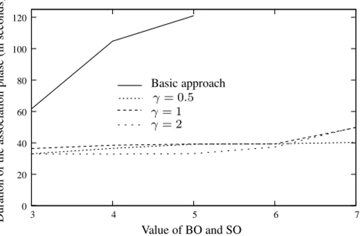
Figure 8 illustrates the average duration of the association phase as a function of BO, with BO=SO, for a network size of 100 nodes. First of all, it is important to notice that the basic approach did not produce results for BO=SO=6 and BO=SO=7. Indeed, the percentage of associated nodes was very small in these cases (see Fig. 5). It turned out that none of our 100 simulations did associate all the nodes of the network. On the other hand, ATA is able to compute an average duration of 30 seconds to 50 seconds, for all the values of BO. When compared with the basic approach (even for the instances where the basic approach was able to associate all the nodes), the gain of ATA is significant. Another interesting aspect about ATA is that it is able to maintain rather stable performance in terms of association duration.
Figure8. ATA outperforms the basic approach when there is no inactivity period.
0 20 40 60 80 100 120 3 4 5 6 7 D u ra ti o n o f th e as so ci at io n p h as e (i n se co n d s) Value of BO and SO Basic approach γ = 0.5 γ = 1 γ = 2
Figure 9 shows the performance of the basic approach and of ATA, in term of associ-ation durassoci-ation, as we vary the duty cycle of the nodes (by varying SO with a constant
BO=7). The association duration increases with SO: when nodes are active during a long period, they generate a large number of control messages which overload the network. ATA outperforms the basic approach as it is able to associate all the nodes between 35 seconds to 50 seconds, while the basic approach requires at least 60 sec-onds for small values of SO, and is unable to associate all the nodes for large values of SO.
Figure9. ATA shows better performance than the basic approach, even when nodes can save energy by switching to sleep mode.
0 20 40 60 80 100 120 3 4 5 6 7 D u ra ti o n o f th e as so ci at io n p h as e (i n se co n d s) Value of SO (BO=5) Basic approach γ = 0.5 γ = 1 γ = 2 CONCLUSION
In a WSN, it is important to reduce the duration of the association procedure, as it delays the data transmission. Unfortunately, the association procedure of IEEE 802.15.4/ZigBee requires a large time (which is even unbounded sometimes) to be accomplished. In this paper, we propose the ATA mechanism that enables nodes to initiate their association procedure at the right time, rather than when they are deployed. In our mechanism, nodes wait until they overhear specific messages to deduce a time at which some of their neighbors might be associated. Then, these non-associated nodes become active after a random backoff in order to reduce the contention produced by association messages.
We evaluated our mechanism on several random network topologies, as a function of the duty cycle and of the number of nodes. Our simulations show that ATA is able to greatly improve the association phase by significantly reducing its duration (from 40% to 70%). We also show that we significantly increase the number of nodes that can be associated (from 15% to 50%). Lastly, ATA has the interesting property that the association duration does not increase rapidly with the network size. As a result, ATA can be used in a large variety of scenarios, as it does not make strong assumptions on the protocols used.
ACKNOWLEDGMENT
This work has been partially supported by a research grant from the Lebanese National Council for Scientific Research (LNCSR).
References
Abbagnale, A., Cipollone, E., and Cuomo, F. (2009). “A case study for evaluating IEEE 802.15.4 wireless sensor network formation with mobile sinks”. In IEEE
ICC.
Callaway, E., Gorday, P., Hester, L., Gutierrez, J., Naeve, M., Heile, B., and Bahl, V. (2002). “Home networking with IEEE 802.15.4: A developing standard for low-rate wireless personal area network”, IEEE Communications Magazine, Vol 40, No 8, pp 70–77.
El Rachkidy, N., Guitton, A., and Misson, M. (2009). “Optimizing the setup phase of an IEEE 802.15.4 wireless sensor network”. In Wireless Days (IFIP Wireless
Days).
He, T., Krishnamurthy, S., Stankovic, J. A., Abdelzaher, T., Luo, L., Stoleru, R., Yan, T., Gu, L., Hui, J., and Krogh, B. (2004). “Energy-efficient surveillance system using wireless sensor networks”. In International Conference on Mobile
Systems, Applications and Services, pages 270–283.
IEEE 802.15 (2006). “Part 15.4: Wireless medium access control (MAC) and phys-ical layer (PHY) specifications for low-rate wireless personal area networks (WPANs)”. Standard 802.15.4 R2006, ANSI/IEEE.
Juang, P., Oki, H., Wang, Y., Martonosi, M., Pen, L. S., and Rubenstein, D. (2002). “Energy-efficient computing for wildlife tracking: design tradeoffs and early experiences with ZebraNet”, ACM SIGOPS Operating Systems Review, Vol 36, No 5, pp 96–107.
Jun, J. and Sichitiu, M. L. (2003). “The nominal capacity of wireless mech networks”,
IEEE Wireless Communications Magazine, Vol 10, pp 8–14.
Zheng, J. and Lee, M. J. (2004). “Will IEEE 802.15.4 make ubiquitous network a reality?: A discussion on a potential low power, low bit rate standard”, IEEE
Communications Magazine, Vol 27, No 6, pp 23–29.
ZigBee (2008). “ZigBee Specification”. Standard Zigbee 053474r17, ZigBee Stan-dards Organization.