HAL Id: in2p3-00331809
http://hal.in2p3.fr/in2p3-00331809
Submitted on 23 Jun 2009HAL is a multi-disciplinary open access archive for the deposit and dissemination of sci-entific research documents, whether they are pub-lished or not. The documents may come from teaching and research institutions in France or abroad, or from public or private research centers.
L’archive ouverte pluridisciplinaire HAL, est destinée au dépôt et à la diffusion de documents scientifiques de niveau recherche, publiés ou non, émanant des établissements d’enseignement et de recherche français ou étrangers, des laboratoires publics ou privés.
alkali ion beam development for SPIRAL1
M. Dubois, J.A. Alcantara-Nunez, R. Alves Condé, C. Barué, C. Canet, M.
Dupuis, J.L. Flambard, R. Frigot, P. Jardin, C. Leboucher, et al.
To cite this version:
M. Dubois, J.A. Alcantara-Nunez, R. Alves Condé, C. Barué, C. Canet, et al.. Permanent magnets under irradiation and radiocative alkali ion beam development for SPIRAL1. 18th International Workshop on ECR Ion Sources - ECRIS2008, Sep 2008, Chicago, United States. �in2p3-00331809�
PERMANENT MAGNETS UNDER IRRADIATION AND
RADIOACTIVE ALKALI ION BEAM DEVELOPMENT FOR SPIRAL 1
M. Dubois, J. Alcántara-Núñez, R. Alves-Condé, C. Barué, C. Canet, M. Dupuis, J.L. Flambard,
R. Frigot, P. Jardin, C. Leboucher, N. Lecesne, P. Lecomte, P. Leherissier, F. Lemagnen,
J.Y. Pacquet, A. Pichard, M.G. Saint-Laurent, GANIL, CEA/DSM-CNRS/IN2P3, F-14076 Caen,
France
Abstract
Up to now, eighteen Target Ion Source Systems (TISSs) have been built and used for the production of radioactive ion beams on SPIRAL 1 facility, based on the Isotope- Separator-On-Line (ISOL) method. The TISSs are composed of thick carbon targets and of fully permanent- magnet Electron Cyclotron Resonance Ion Sources (ECRISs) of the Nanogan III type. After irradiation and a decay period of two years, the irradiated TISSs are dismounted and if their magnetic fields are still suitable, the ECRIS are used with a new target. Thereby thirty-two runs have been performed using new or renewed TISSs. , After irradiation, the measured magnetic field sometimes reveals magnet damage. Our experience is reported here. In the second section, we present the progress on the NanoNaKE setup, which aims to extend the radioactive ion beams in SPIRAL 1 to the alkali elements, by connecting a surface-ionization source to the Nanogan III ECRIS via a compact 1+ ion beam line. The main issues and difficulties are discussed and the preliminary solutions are described.
INTRODUCTION
The use of high-energy fragmentation as well as the ISOL methods for exploring the structure of nuclei far from the stability has become one of the major activities at GANIL (Grand Accelerateur National d’Ions Lourds). The ISOL method, used in SPIRAL, provides radioactive ion beams, with subsequent acceleration by a K=265 cyclotron CIME, (Cyclotron d’ Ions à Moyenne Energie).
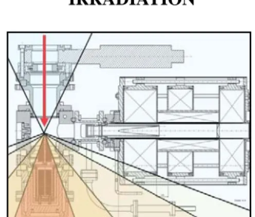
Three cyclotrons are used to produce the primary beam which bombards the target of the TISS (Figure 1) placed in a heavily shielded cave. Exotic nuclei produced by nuclear reactions are released from the high temperature target (2000°C), effuse through a cold transfer tube up to a multi-charged ECR ion source. After extraction from the ECRIS at low energy (≤ 34 q.keV), the beam of interest is selected by a magnetic spectrometer (m /Δm = 250) and injected into CIME. The exotic beams can be accelerated in an energy range of 1.7 to 25 MeV/u and, after extraction, the proper magnetic rigidity is selected by GANIL’s modified alpha spectrometer and directed to one of the existing experimental areas.
Two kinds of carbon target are used for the radioactive ion beam production, one dedicated to the production of He isotopes, the other to heavier gaseous element up to Krypton. The restriction to gaseous elements is provided
by a cold transfer tube, situated between the target cavity and the source chamber. Available intensities are given on the GANIL web site [1]
PERMANENT MAGNETS UNDER
IRRADIATION
Figure 1: angular distribution of neutrons downstream from the target
The carbon target is placed close to the permanent magnets of the ion source (Nanogan III), which can then be damaged by neutron irradiation, leading to losses in axial and radial confinement of the source. For this
reason, after a radioactive decay periodof some years, the
irradiated TISSs are placed in a glove box and dismounted. The target part is discarded as nuclear waste, and the magnetic field of the ion source is measured: if it is still acceptable, the ion source is reassembled with a new target.
During recent years, magnetic measurements have revealed more and more damage. Among the eighteen TISSs constructed since 2001, two types of degradation have been observed:
(a) Degradation of the injection magnet (close to the
target):
Figure 2 shows an example of the decrease of the axial magnetic field on the injection side, with no modifica-tion at the opposite (or extracmodifica-tion) side.
Measurements all around the injection magnet (Figure 3) show an average loss of magnetic field of about 20%, with a maximum of 40% on the target side.
B 0 1000 2000 3000 4000 5000 6000 7000 8000 0 50 100 150 200 250 Position (mm) A xi al M ag n eti c fi el d ( G au ss) After irradiation Before irradiation
Figure 2: axial magnetic field before and after irradiation
along the axis of the ECRIS. Figure 5: Coercivity of permanent FeNdB magnets
(Vacodym 655HR) for different temperatures. B is the remanence field and H is the opposite magnetic fields.
5000 6000 7000 8000 9000 10000 11000 0h 1h 2h 3h 4h 5h 6h 7h 8h 9h 10h 11h
After irradiation Theorical field T a r g e t s i d e
• Particle effect on the permanent magnets
Neutrons, protons, gamma rays and light fragments produced by primary beams of energy ranging from 60 A.MeV to 95 A.MeV striking a carbon target can reach and damage the magnets [2]. Neutrons especially, with energies up to 95 MeV, have a high cross section for interaction with the boron contained in the magnets, and can thus damage them by microscopic structural modifications of the material.
Figure 3: radial magnetic field measured on the injection magnet (left) and schematic of the measurement method (right).
(b) Damage to the hexapole:
The magnetic components of all the irradiated TISSs cannot be fully dismounted to do a fine diagnosis, particularly for the hexapole structure. Thus all the refurbished sources are tested on a dedicated test bench to ensure the same test conditions during the tests, allowing us to make a comparison of the performance of the respective sources. The charge state distribution of the argon spectrum (fig. 6) is taken as a reference to determine if a TISS is suitable for use in the SPIRAL ISOL process.
A significant decrease of the radial magnetic field has also been measured on different TISSs (Figure 4).
-800 -600 -400 -200 0 200 400 600 800 0 60 120 180 240 300 Before irradiation After irradiation 0 10 20 30 40 50 1 2 3 4 5 6 7 8 9 10 11 Charge State % P a rt ic u le s Before irradiation Injection default hexapôle default
Figure 4: Radial magnetic field of the hexapole structure before and after irradiation (left side), and schematic of the measurement method (right).
This damage to the magnets can be explained by the coercivity of the magnets and by the intensity of the neutron flux
• Coercivity of the magnets Figure 6: Influence of the state of the magnetic structure
on the charge state distribution of argon. One important characteristic of the magnets is their
coercivity, which corresponds to the maximum magnetic field they can withstand without magnetic changes. Moreover, this maximum strongly depends on the temperature (Figure 5). In the case of the NANOGAN III ECRIS, some magnets are subjected to fields close to the maximum
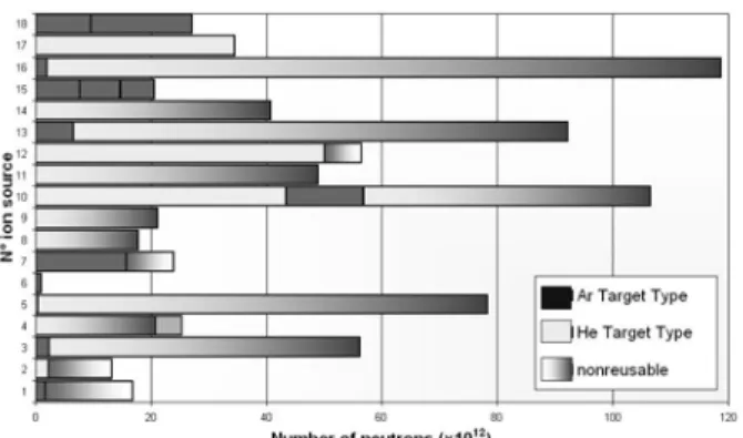
Two types of target are used on SPIRAL, one for He production, and one for heavier gas production. Owing to the position of the He target, closer to the source axis than the other, and because the first degradation occurred with “He type” targets, we thought that the magnets were exposed to a more intense neutron flux.
This assumption was not confirmed, after we calculated
the number of neutrons seen by each ion source. • Losses by interaction of the 1+ beam with the backward N+ ion beam extracted from the ECR ion
source.
Since the target and 1+ ion source system has previously been characterized, it has been removed and replaced by an alkali ion gun, which is easier to use: the emerging ion current easily can be measured, and it can be chopped, which is important to determine if the multi-charged ions observed at the exit of the ECRIS come from a slow conversion process (migration of atoms from the 1+ to the ECRIS and ionization) or from a fast conversion process (transport as 1+ ions from the 1+ to the ECRIS, capture and charge breeding). The behavior of the ion gun and the transport in the beam line have been previously simulated using the CPO (Charged Particle Optics) program [5] and SIMION [6] codes
Figure 7: Reference number of each irradiated source versus total neutron number seen by the source. The different shading correspond to the type of target used for the run. A darker shade means the ion source cannot be
reused.
Experimental measurements
CONCLUSION
We are not able to predict when the ion source will become unusable. The damage to the magnets depends on the neutron flux, but also on the primary beam features (energy, intensity, position on the target) and on the kind of target.
As on-line diagnosis is not possible while the beam is delivered to the physics experiments, we check the performance of each ion source at the end of a run, and check the magnetic field after the storage period and we also check the off-line performance of the source on a test bench before using the TISS in the production cave.
Cathode
1+ source
Extraction
Lens Faraday
cup
Figure 8: Setup for calibrating the alkali ion gun
The current and time calibration of the 1+ alkali ion gun was performed with a dedicated setup (Figure 8), for a maximum
RADIOACTIVE ALKALI ION BEAM
DEVELOPMENT FOR SPIRAL 1: ISSUES
39K current of 15µA. +In the framework of the production of multi-charged radioactive alkali ion beams in SPIRAL 1 at GANIL, a surface ionization source associated with the multi-charged ECR NANOGAN III [3] has been developed to produce singly-charged ions of Na and K. The system, called NanoNaKE, produces radioactive atoms in a carbon target, which diffuse and effuse into a surface ionizer. Once ionized, they are accelerated by an extraction electrode to form a beam, which is shaped by an electrostatic lens to go through a drift tube before entering the ECRIS chamber. This very compact system has demonstrated the possibility to convert
After calibrating the alkalis ion gun, the system was installed on the NanoNaKE setup.
0,0 0,2 0,4 0,6 0,8 1,0 0 5 10 15 20 25 30 DV (V) 1 + b e am l in e T ran sp o rt E ff ic ien cy 47K ions into +
47K ions, but with an efficiency somewhat lower than 5+
that expected [4]. Figure 9: 1+ beam line transport efficiency versus voltage
difference ΔV applied between the 1+ ion source and the
ECR potential. These low efficiency results could have different
origins: One of the main conclusions is that a voltage difference
ΔV applied between the 1+ ion gun and the ECRIS potential must be higher than 12V to obtain a transport efficiency higher than 80%. But this value may be too • Losses during the 1+ beam transport by the spread in
energy and angle induced by interaction of the 1+ ion beam with the residual gas coming from the hot parts of the system (i.e. the oven and ionizer) and
Owing to the design of the present beam line, several problems occur: at low ΔV, the current extracted from the alkali emitter decreases up to values difficult to observe, and the focus of the beam does not act as expected from simulations and the losses increase strongly. Moreover, the lack of physical separation between the different electrostatic electrodes induces a coupling of their effects. Finally, for a voltage of some hundreds of volts – which is a minimum to transport a 1+ beam while minimizing the losses – a Penning discharge appears on the beam line, inducing currents on the different electrodes much higher than the 1+ ion beam current, thus making it difficult to determine the transport efficiency.
0,0 0,2 0,4 0,6 0,8 1,0
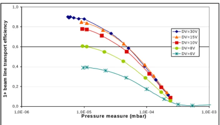
1,0E -06 1,0E -05 1,0E-04 1,0E -03
P res sure m ea su re (m ba r) 1 + b e a m li n e tr a n s p o rt e ffi c ie n c y DV =30V DV =15V DV =10V DV =8V DV =6V
Figure 10: Gas pressure effect on the 1+ beam line efficiency.
+ beam line transport is probably the rest gas p
background of e ECRIS (when ON) are too large, it has until now not b
A diagnostic study as been made and
several problems h
• a gas pressure effect • coupling of the electrodes
ction potential
sport at low
A new ig.11) is under construction, taking
ccount all these problems. The next tests should be
Figure 11: New 1+ beam line design
eferences:
site : http://www.ganil.fr
These “Study of multicharged radioactive hods in Physics
Thesis, Grenoble (2000) • limited value of extra
• Penning discharge.
• a difficulty in simulating ion tran energy ( 10V)
1+ beam line (f a
performed by the end of 2008. New Characteristics: - Better vacuum (~10-6 mbar, 1+ beam line)
- Will be possible to extract the beam at higher energy (ΔV up to 1KV) - Independent lectrodes
Design
As shown in Figure 10, one main origin of the losses during the 1
ressure. In our case, the order of magnitude of the
pressure was estimated to some 10-4 mbar.
As the losses during the transport and the th
een possible to observe the charge breeding conversion.
CONCLUSION
of the 1+ beam line h ave been revealed:
R
[1] GANIL web [2] N. Lecesne.
ions production on line”. (1997) p 112.
[3] C. Eléon et al., Proceedings of EMIS 2007, to be published by Nucl. Instrum. and Met
Research, Section B (NIMB).
[4] C. Eléon et al., Proceedings of ICIS07, to be published in Rev. Sci. Instrum.
[5] CPO Programs, available on the web site http:// electronoptics.com [6] SIMION Program. [7] N. Chauvin, PhD Cathode Extractor Diaphragm Lens Diaphragm Drift tube