HAL Id: hal-01486885
https://hal.archives-ouvertes.fr/hal-01486885
Submitted on 10 Mar 2017
HAL is a multi-disciplinary open access
archive for the deposit and dissemination of
sci-entific research documents, whether they are
pub-lished or not. The documents may come from
teaching and research institutions in France or
abroad, or from public or private research centers.
L’archive ouverte pluridisciplinaire HAL, est
destinée au dépôt et à la diffusion de documents
scientifiques de niveau recherche, publiés ou non,
émanant des établissements d’enseignement et de
recherche français ou étrangers, des laboratoires
publics ou privés.
Thermal cycling and reactivity of a MoSi2/ZrO2
composite designed for self-healing thermal barrier
coatings
Franck Nozahic, Daniel Monceau, Claude Estournès
To cite this version:
Franck Nozahic, Daniel Monceau, Claude Estournès. Thermal cycling and reactivity of a MoSi2/ZrO2
composite designed for self-healing thermal barrier coatings. Materials and Design, Elsevier, 2016, vol.
94, pp. 444-448. �10.1016/j.matdes.2016.01.054�. �hal-01486885�
O
pen
A
rchive
T
OULOUSE
A
rchive
O
uverte (
OATAO
)
OATAO is an open access repository that collects the work of Toulouse researchers and
makes it freely available over the web where possible.
This is an author-deposited version published in :
http://oatao.univ-toulouse.fr/
Eprints ID : 16738
To link to this article : DOI:10.1016/j.matdes.2016.01.054
URL :
http://dx.doi.org/10.1016/j.matdes.2016.01.054
To cite this version :
Nozahic, Franck and Monceau, Daniel and
Estournès, Claude Thermal cycling and reactivity of a MoSi2/ZrO2
composite designed for self-healing thermal barrier coatings.
(2016) Materials and Design, vol. 94. pp. 444-448. ISSN 0261-3069
Any correspondence concerning this service should be sent to the repository
administrator:
staff-oatao@listes-diff.inp-toulouse.fr
Thermal cycling and reactivity of a MoSi
2
/ZrO
2
composite designed for
self-healing thermal barrier coatings
Franck Nozahic
a,b, Daniel Monceau
a,c,⁎
, Claude Estournès
b,caCIRIMAT, équipe MEMO, ENSIACET, 4 Allée Emile Monso, 31030 Toulouse, France
bUniversité de Toulouse, UPS, équipe NNC, Institut Carnot Cirimat, 118 Route de Narbonne, F-31062 Toulouse, France cCNRS, Institut Carnot Cirimat, F-31062 Toulouse, France
a b s t r a c t
Consolidated (relative density of 84%) composite made of molybdenum di-silicide (MoSi2) particles dispersed in
a yttria partially stabilized zirconia matrix (8Y2O3–Zr02) was prepared by spark plasma sintering. Cyclic oxidation
of the composite at temperature ranging from 1000 °C to 1300 °C was studied. Parabolic rate constants (kp)
values of the composite material are in good agreement with those obtained in the literature for the oxidation of bulk MoSi2. Following oxidation exposure, formation of Mo5Si3, SiO2and ZrSiO4phases was observed. These
observations are compatible with the use of MoSi2as a self-healing agent in YPSZ thermal barrier coatings.
Keywords:
Spark plasma sintering Ceramic matrix composites (CMC) Intermetallic compounds Cyclic oxidation
Cyclic Thermogravimetric Analysis (CTGA)
1. Introduction
Thermal barrier coatings (TBCs) made of yttria partially stabilized zirconia (YPSZ), deposited by plasma-spraying, are widely used to in-crease the durability of hot-section metal components in advanced gas-turbine for aircrafts and power generation[1–4]. YPSZ is used for high temperature applications due to its mechanical strength and chemical stability at such temperatures. However, as a ceramic, YPSZ suffers from a relatively low toughness. TBCs failure is governed by a se-quence of initiation, propagation and coalescence of cracks that leads to spallation of the TBC, exposing the hot-section metal components to the high-temperature environment[5]. Hence, a TBC that is capable of auto-nomic crack repair and structural integrity recovery in a high-temperature oxidizing environment is highly desirable. Recently, Sloof et al.[6,7]proposed the concept of a new self-healing thermal barrier coating based on the oxidation of boron doped molybdenum di-silicide (B-MoSi2) healing particles embedded in the ZrO2-based TBC.
Healing particles intercepted by cracks will oxidize preferentially, lead-ing to the formation of amorphous SiO2, which flows into cracks and
es-tablishes direct contact with the crack faces. The wetting of the crack faces is followed by a chemical reaction with the ZrO2-based TBC coating
leading to the formation of a load bearing ZrSiO4phase.
MoSi2exhibits a high melting point (2020 °C)[8], it has a density
close to YPSZ (MoSi2= 6.24 g·cm− 3, YPSZ = 6.08 g·cm− 3)[8,9], it
shows a high oxidation resistance at elevated temperature, and its coef-ficient of thermal expansion (CTE) matches reasonably with the one of YPSZ (MoSi2= 8.1 × 10− 6°C− 1, stabilized ZrO2= 10 × 10− 6°C− 1)
[10,11]which means that thermal stresses induced by the mismatch of the respective CTEs will be minimal. YPSZ are widely used as solid electrolytes in Solid Oxides Fuel Cells (SOFC) since they are recognized as oxygen ion conductors at elevated temperatures[12,13]. Meaning that oxygen ion can pass easily through the YPSZ matrix to oxidize the dispersed MoSi2particles.
For the current work, a partially densified composite (relative densi-ty of 84%) made of a YPSZ matrix containing 20 wt.% of MoSi2particles
has been prepared using spark plasma sintering (SPS). The high temper-ature behavior of such composite under air atmosphere has been stud-ied using Cyclic Thermogravimetric Analysis (CTGA)[14]and the phase transformations during the process have been examined.
2. Experimental procedure
Appropriate amounts of YPSZ containing 7–8 wt.% Y2O3(average
grain size: 45 μm) and MoSi2(average grain size: 19 μm) particles
were mechanically dry mixed for 1 h in a Turbula-type powder blender. The volume fraction of MoSi2particles was 20%. The composite material
(referred as YSZ-20MoSi2) used in this study was produced with a Dr.
Sinter SPS-2080 equipment (SPS Syntex Inc., Kanagawa, JP) located at the Plateforme Nationale de Frittage Flash (PNF2, CNRS CIRIMAT,
⁎ Corresponding author at: équipe MEMO, ENCIASET, 4 Allée Emile Monso, 31030 Toulouse, France.
E-mail address:daniel.monceau@ensiacet.fr(D. Monceau).
Université Toulouse III Paul Sabatier, France). A 30 mm inner diameter graphite die covered with a graphite foil (Papyex® Mersen) was filled with the powder mixture and mounted into the SPS equipment. SPS was completed with a fixed heating rate of 100 °C·min− 1, up to
1500 °C, with a soaking time of 5 min at this temperature and under a constant macroscopic compaction uni-axial pressure of 100 MPa ap-plied since the beginning of the sintering cycle. The temperature was monitored by an optical pyrometer focused on a small hole (3 mm in depth) located at the external surface of the die. The electric current was applied by pulses following the standard 12/2 (on/off 3.3 ms) pulse pattern. The relative density of the sample was about 84% after SPS. Such level of porosity (16 vol.%) was performed in order to repro-duce the one of industrial TBC. A specimen of 10 × 10 × 2 mm3with
parallelepiped-like shape was cut from the sintered sample. All surfaces were wet grinded using SiC papers down to P600.
Cyclic oxidation experiment was performed on this specimen in flowing synthetic dry air (flux = 5 ml·min− 1, gas velocity =
0.85 mm·s− 1), using a commercial thermobalance (Setaram TAG24s).
The experiment consisted of 10 cycles at 1000 °C followed by 10 cycles at 1100 °C, 1200 °C and 1300 °C, with dwell times of 3600 s at high tem-perature and 6250 s down to 50 °C. Heating rate and initial cooling rate were controlled at 60 °C·min− 1and data were recorded in real time,
in-cluding during heating and cooling.
Following the above mentioned oxidation test, the specimen was promptly removed from the equipment and polished with 1 μm dia-mond suspension. The cross-section was examined by a scanning elec-tron microscope (LEO435VP) equipped with an energy dispersive X-ray (EDX) spectroscopy system. The oxidized specimen was investigat-ed by X-ray diffraction (XRD) for phase identification. Image analysis was performed using the “Image J” software to determine the surface percentages of the different phases of the material after oxidation. 3. Results and discussion
3.1. Synthesis of the YSZ–20MoSi2composite
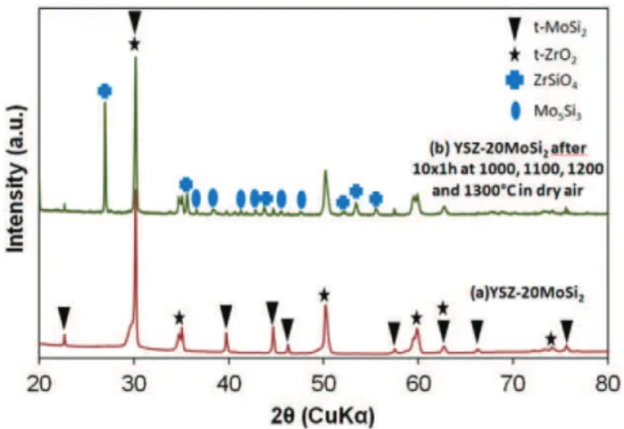
The microstructure and the XRD pattern of the sintered composite (referred as YSZ–20MoSi2) are shown inFig. 1andFig. 2(a). Results of
the XRD analysis of the composite after cyclic oxidation (Fig. 2(b)) will be discussed later. It can be observed that the MoSi2particles are
homogeneously distributed in the YPSZ matrix. Based on the analysis of optical microscope images, the level of porosity is estimated to be 16 vol.%. XRD of the composite indicates that it consists of tetragonal zir-conia and tetragonal MoSi2and that no visible reaction has occurred
be-tween the YPSZ matrix and the MoSi2 particles as a result of the
sintering process.
3.2. Cyclic oxidation of the YSZ–20MoSi2composite in air
The plot of the net mass change versus time for cyclic oxidation of the composite at 1000, 1100, 1200, 1300 °C is shown inFig. 3. A parabola-like shape is observed for all temperature regimes. A SEM mi-crograph of a cross section of the oxidized material after the complete cyclic oxidation experiment is given inFig. 4(a). No visible cracks were observed resulting from stresses that would be induced either by volume increase caused by oxide growth or thermally induced by differ-ent CTE of grown oxides, MoSi2particles and YPSZ matrix. This is
consis-tent with a previous work of Petrovic and Honnell[15] on MoSi2
composites containing PSZ inclusions prepared by hot pressing. A con-tinuous layer of silica with a uniform thickness of 0.6 μm is observed around MoSi2particles as a result of the selective oxidation of silicon
from the MoSi2substrate, according to the Eq.(1) [16].
5MoSi2 sð Þþ 7O2 gð Þ→Mo5Si3 sð Þþ 7SiO2 sð Þ ð1Þ
The formation of a dense protective SiO2scale, above 1000 °C, is
re-sponsible for the high oxidation resistance of MoSi2[17]. The low
oxy-gen partial pressure at the SiO2/MoSi2 interface prevents the
formation of volatile MoO3. XRD analysis (Fig. 2(b)) did not enable to
identify the structural type of the silica layer. According to Berztiss et al.[8], silica formed on MoSi2was found to be in the amorphous
state up to 1700 °C, while two other research groups claimed that the silica scale has a crystalline structure of tridymite from 1000 to 1200 °C[16]and cristobalite from 1300 to 1400 °C[16,18].
Fig. 1. Cross-section of the composite observed with optical microscope showing MoSi2
particles (white), YPSZ matrix (light gray) and porosities (dark gray).
Fig. 2. XRD patterns of: (a) sintered YSZ–20MoSi2composite; (b) sintered YSZ–20MoSi2
composite exposed to flowing dry air for 10 × 1 h at 1000, 1100, 1200 and 1300 °C.
Fig. 3. Evolution of the net mass change of the composite sample exposed to flowing dry air for 10 × 1 h at 1000, 1100, 1200 and 1300 °C in a cyclic thermogravimetric apparatus.
A Mo5Si3phase, in lighter gray than the other two phases, is
ob-served at the surface of the MoSi2particles in contact with a SiO2
layer, highlighting a local silicon depletion in this zone. The formation of this phase leads to rapid consumption of Si through oxidation to form the silica layer and is in agreement with the thermodynamic pre-dictions (Eq.(1)). Further dissociation of Mo5Si3is not necessary to
achieve the growth of the silica scale because the diffusion rate of silicon in Mo5Si3is considerably higher than the diffusion rate of the oxygen in
SiO2for temperatures above 1200 °C[19]. However, in case of contact
with high oxygen partial pressure (PO2), Mo5Si3can be further oxidized
into MoO3and SiO2following Eq.(2) [16].
2Mo5Si3 sð Þþ 21O2 gð Þ→10MoO3 gð Þþ 6SiO2 sð Þ ð2Þ
Complete silicon and molybdenum exhaustion can be observed for small particles leading to the disappearance of the Mo5Si3phase for
lon-ger oxidation times, as reported by Zhu et al.[16]. In this case, Mo5Si3is
fully oxidized into MoO3and SiO2according to Eq.(2).
An additional phase ZrSiO4is observed as a result of the reaction
be-tween the SiO2phase and the ZrO2matrix according to Eq.(3) [20].
SiO2 sð Þþ ZrO2 sð Þ→ZrSiO4 sð Þ ð3Þ
According to the ZrO2–SiO2phase diagram, proposed by Butterman
and Foster[21], pure zircon is a stable phase that decomposes into t-ZrO2and SiO2(cristobalite) at a temperature approximately 1676 °C.
The formation of zircon at a temperature as low as 1300 °C is in agree-ment with previous studies[20,22]. According to Itoh[20], zircon starts forming around 1200 °C and results exclusively from the reaction be-tween amorphous silica and tetragonal zirconia. This reaction is sup-posed to predominate the transformation of amorphous silica into cristobalite. Mao and Sloof [22] affirmed that zircon can form at 1100 °C in air from cold pressed mixtures of YPSZ and MoSi2powders.
In the present study, it was observed that a layer of zircon, with a thickness of about 0.5 μm, is formed around the original MoSi2particles,
between the silica scale and the zirconia matrix. It should be noted that zircon is also located at the zirconia grain boundaries at a distance up to 19 μm away from the MoSi2particle. The thickness of the zircon located
Fig. 4. Cross section BSE image of the composite sample exposed to flowing dry air for 10 × 1 h at 1000, 1100, 1200 and 1300 °C (a) and example of image analysis on the composite: (b) gray value histogram of the BSE image (0 = pure black, 255 = pure white); (c, d, e, f) thresholding of the different phases.
at the grain boundaries is 2.5 times as high as the thickness of the zircon located at the interface between MoSi2particles and the surrounding
YPSZ grains. This implies that atomic diffusion of silicon in solid state can proceed, in the grains boundaries of the YPSZ matrix, at long dis-tances from the MoSi2particles. This observation is of interest for the
concept of a self-healing TBC[6]. According to Veytizou et al.[23]and marker experiments of Eppler[24], it is suggested that Si4+is the fastest
cation. Leading to the deduction that its diffusion through the zircon layer is the limiting step of the zircon formation mechanism at the zir-con/zirconia interface.
Image analysis was performed to determine surface percentages of the different phases of the material after oxidation (Fig. 4). Plots of the surface area fractions of the different phases of the composite after oxi-dation and for different depths from the surface are shown inFig. 5. The fraction of zirconia transformed into zircon is about 16% after the overall cyclic oxidation experiment. The phase fractions of SiO2and ZrSiO4at
50 μm depth are 24% and 18% higher than those at 5000 μm depth re-spectively. However, the diffusion rate of oxygen in Y2O3-doped ZrO2
is several orders of magnitude higher than the diffusion rates of the ox-ygen in SiO2and ZrSiO4for temperatures above 1000 °C[25–28]. This
means that zircon formed at the grain boundaries of the YPSZ matrix acts as a diffusion barrier for oxygen in-depth ingress in the material, just by decreasing the diffusion section (i.e. the ZrO2volume fraction).
The increase of the amount of oxygen in the specimen was estimated by measuring the fraction of SiO2and ZrSiO4. The estimated mass gain
due to oxygen uptake in ZrSiO4and SiO2grow is in close match with
the one measured from the CTGA experiment (46 and 42 mg respective-ly). This indicates that if MoO3sublimation occurs, it is limited.
Further-more, no MoO3crystals were found in the silica scale after cooling from
the oxidation tests or deposited in the cooler parts of the apparatus. No signs of bubbling were observed. This confirms that, in these conditions, the formation of a dense silica scale prevents or drastically reduces MoO3evaporation in this case.
3.3. Discussion
Plotting the oxidation-induced net mass change versus time shows a large mass gain for a silica former material (Fig. 3). This is explained by the large surface area of the reacting MoSi2particles. The total surface of
the oxidation-reactive surface for the MoSi2particles embedded in the
zirconia matrix was determined prior to oxidation tests by using
image analysis technique. A surface area of 683 cm2was measured,
which is almost 200 times higher than the geometrical external surface area of the specimen. As a first approximation, parabolic rate constants (kp) were determined by considering a constant reactive surface even
though the surface is expected to slightly decrease with time. The fitting of the thermogravimetric curves by a complete parabolic law enabled to determine kpvalues at different temperatures, independently of the net
mass change due to oxidation at lower temperatures[29]. These kp
values are given inTable 1. No mass loss was observed due to a transient oxidation mechanism with competitive oxidation of silicon and molyb-denum leading to the formation of a non-protective silica layer and vol-atile MoO3, as observed by Knittel et al.[30]. A continuous mass gain
was observed for all oxidation temperatures.
At the starting oxidation temperature of 1000 °C, high initial mass gain is observed prior to the establishment of a protective silica layer forming a diffusion barrier. For these temperature regimes, the oxida-tion of MoSi2covered by a dense and protective layer is known to be
controlled by the slow inward diffusion of oxygen through the silica layer[31]. A clear weight gain is observed when changing temperature regime and then slowed down for longer oxidation times. The kpvalue
of the composite material at 1300 °C is 12 times higher than at 1000 °C. Despite the approximation concerning the constant surface area of the particles, the kpvalues of the composite material are in good agreement
with those obtained in the literature for the oxidation of bulk MoSi2[18,
30].
The thickness of the silica layer can be compared with the one calcu-lated from the mass gain assuming that mass gain is predominantly due to oxygen uptake to grow silica. The predicted thickness is 1 μm by using a kpvalue of 3.97 × 10− 7mg2·cm− 4·s− 1for a uniaxial hot pressed
MoSi2in air at 1300 °C for 10 h obtained by Knittel et al.[30]. Thus,
the measured thickness of the silica layer is 40% thinner than expected when considering only oxygen uptake to form silica. This can be ex-plained by the fact that the measured mass change is the sum of the contribution of high oxygen mass gain caused by formation of both ZrSiO4and SiO2and small mass loss due to possible evaporation of
MoO3. The growth of ZrSiO4from ZrO2and SiO2decreases the thickness
of the protective layer of SiO2. Therefore this layer is a less effective
dif-fusion barrier for oxygen ingress and the oxidation kinetics are expected to slightly increase. But the ZrSiO4layer on top of the silica is also a
dif-fusion barrier which could decrease the oxidation kinetics of silicon. More generally, a general kinetic model which takes into account the diffusion of the species in the multiple layers of the system, and perhaps also the rates of reaction at the interfaces, needs to be built to fully as-sess the oxidation-kinetics of the ZrO2–MoSi2composite.
4. Conclusion
Consolidated (relative density of 84%) composite made of MoSi2
par-ticles dispersed in a yttria partially stabilized ZrO2matrix has been
pre-pared by SPS. The oxidation of the composite under dry air for 10 h at 1000/1100/1200/1300 °C has been investigated. The oxidation parabol-ic rate constant kpvalues of the composite material are in fair agreement
with those reported in the literature for the oxidation of bulk MoSi2,
tak-ing into account that the reactive surface area is the one of the embed-ded MoSi2 particles and despite the geometric and kinetics
approximations that were used. The oxidation results in the formation of a continuous SiO2layer around MoSi2particles. Mo5Si3phase is
formed under the silica scale due to a local silicon depletion zone
Table 1
Parabolic rate constants values (kp) of the Y2O3-partially stabilized ZrO2dispersed MoSi2particles composite and kpvalues from the literature for bulk MoSi2materials.
Temperature (°C) 1000 1100 1200 1300
kp(mg2·cm− 4·s− 1) Present study 3.0 × 10− 9 6.3 × 10− 9 1.2 × 10− 8 3.7 × 10− 8
Knittel et al.[30] 2.1 × 10− 9 x 4.7 × 10− 8 4.0 × 10− 7
Meilsheimer et al.[18] 2.1 × 10− 8 4.7 × 10− 8 x x
Fig. 5. Surface area fractions of the different phases after oxidation of 10 × 1 h at 1000, 1100, 1200 and 1300 °C in flowing dry air.
formed at the surface of the MoSi2particles. For long exposition times,
an additional ZrSiO4phase is observed as a result of the reaction
be-tween formed silica and YPSZ matrix. ZrSiO4is formed both around
the MoSi2particles and at the grain boundaries of the YPSZ matrix.
The ZrSiO4layer formed around the silica layer does not affect much
the oxidation kinetics. Also, it is interesting to note that ZrSiO4is
ob-served far away from the MoSi2particles. This can be very beneficial
for the self-healing mechanism of the composite. Acknowledgments
This project has received funding from European Union Seventh Framework Program (FP7/2007–2013) under grant agreement no. 309849, SAMBA.
References
[1] R.A. Miller, Thermal barrier coatings for aircraft engines: history and directions, J. Therm. Spray Technol. 6 (1997) 35–42.
[2] S. Bose, J. DeMasi-Marcin, Thermal barrier coating experience in gas turbine engines at Pratt & Whitney, J. Therm. Spray Technol. 6 (1997) 99–104.
[3] M.J. Stiger, N.M. Yanar, M.G. Topping, F.S. Pettit, G.H. Meier, Thermal barrier coatings for the 21st century, Z. Met. 90 (1999) 1069–1078.
[4] N.P. Padture, M. Gell, E.H. Jordan, Thermal barrier coatings for gas-turbine engine applications, Science's Compass 280-4 (2002).
[5] A.G. Evans, D.R. Mumm, J.W. Hutchinson, G.H. Meier, F.S. Pettit, Mechanisms con-trolling the durability of thermal barrier coatings, Prog. Mater. Sci. 46 (2001) 505–553.
[6] W.G. Sloof, S.R. Turteltaub, A.L. Carabat, Z. Derelioglu, S.A. Ponnusami, G.M. Song, Crack healing in yttria stabilized zirconia thermal barrier coatings, Self healing Ma-terials — Pioneering Research in Netherlands 2015, pp. 217–225.
[7] Z. Derelioglu, A.L. Carabat, G.M. Song, S. van der Zwaag, W.G. Sloof, On the use of B-alloyed MoSi2particles as crack healing agents in yttria stabilized zirconia thermal
barrier coatings, J. Eur. Ceram. Soc. 35 (16) (2015) 4507–4511.
[8] D.A. Berztiss, R.R. Cerchiara, E.A. Gulbransen, F.S. Pettit, G.H. Meier, Proceedings of the First High Temperature Structural Silicides Workshop Oxidation of MoSi2and
comparison with other silicide materials, Mater. Sci. Eng. A 155 (1992) 165–181.
[9] E. Withey, C. Petorak, R. Trice, G. Dickinson, T. Taylor, Design of 7 wt.% Y2O3–ZrO2/
mullite plasma-sprayed composite coatings for increased creep resistance, J. Eur. Ceram. Soc. 27 (2007) 4675–4683.
[10] A.K. Vasudévan, J.J. Petrovic, A comparative overview of molybdenum disilicide composites, Mater. Sci. Eng. A 155 (1992) 1–17.
[11] E. Medvedovski, Wear-resistant engineering ceramics, Wear 249 (2001) 821–828.
[12] S.J. Skinner, J.A. Kilner, Oxygen ion conductors, Materials Today 6 (2003) 30–37.
[13] A.J. McEvoy, Thin SOFC electrolytes and their interfaces: a near-term research strat-egy, Solid State Ionics 132 (2000) 159–165.
[14] A. Vande Put, D. Monceau, D. Oquab, Cyclic thermogravimetry of TBC system, Surf. Coat. Technol. 202 (2007) 665–669.
[15] J.J. Petrovic, R.E. Honnell, Partially stabilized ZrO2particle–MoSi2matrix composites,
J. Mater. Sci. 25 (1990) 4453–4456.
[16] Y.T. Zhu, M. Stan, S.D. Conzone, D.P. Butt, Thermal oxidation kinetics of MoSi2-based
powders, J. Am. Ceram. Soc. 82 (1999) 2785–2790.
[17] S. Lohfeld, M. Schütze, A. Böhm, V. Güther, R. Rix, R. Scholl, Oxidation behaviour of particle reinforced MoSi2composites at temperatures up to 1700 °C, Mater. Corros.
56 (2005) 250–258.
[18] S. Melsheimer, M. Fietzek, V. Kolarik, A. Rahmel, M. Schutze, Oxidation of the inter-metallics MoSi2and TiSi2: a comparison, Oxid. Met. 47 (1997) 139–203. [19] R.W. Bartlett, P.R. Gage, Diffusion kinetics affecting formation of silicide coatings on
molybdenum and tungsten, Trans. AIME 233 (1965) 968.
[20] T. Itoh, Formation of polycristalline zircon (ZrSiO4) from amorphous silica and
amorphous zirconia, Crystal Growth 125 (1992) 223–228.
[21] W.C. Butterman, W.R. Foster, Zircon stability and the ZrO2–SiO2phase diagram, Am.
Mineral. 52 (1967) 880–885.
[22] W. Mao, W. Sloof, Kinetics of Self-healing Reaction in TBC with MoSi2Based
Sacrifi-cial Particles, 2013.
[23] C. Veytizou, J.F. Quinson, O. Valfort, G. Thomas, Zircon formation from amorphous silica and tetragonal zirconia: kinetic study and modelling, Solid State Ionics 139 (2001) 315–323.
[24] R.A. Eppler, Mechanism of formation of zircon stains, J. Am. Ceram. Soc. 53 (1970).
[25] M.A. Lamkin, F.L. Riley, R.J. Fordham, Oxygen mobility in silicon dioxide and silicate glasses: a review, J. Eur. Ceram. Soc. 10 (1992) 347–367.
[26] M.S. Khan, M.S. Islam, D.R. Bates, Cation doping and oxygen diffusion in zirconia: a combined atomistic simulation and molecular dynamics study, J. Mater. Chem. 8 (1998) 2299–2307.
[27] X. Li, B. Hafskjold, Molecular dynamics simulations of yttrium-stabilized zirconia, J. Phys. Condens. Matter 7 (1995) 1255.
[28] B. Zhang, X. Wu, Prediction of self-diffusion and heterodiffusion coefficients in zir-con, J. Asian Earth Sci. 42 (2011) 134–141.
[29] D. Monceau, B. Pieraggi, Determination of parabolic rate Constants from a local anal-ysis of mass gain curves, Oxid. Met. 50 (5) (1998) 477–493.
[30] S. Knittel, S. Mathieu, M. Vilasi, The oxidation behaviour of uniaxial hot pressed MoSi2in air from 400 to 1400 °C, Intermetallics 19 (2011) 1207–1215.
[31] C.D. Wirkus, D.R. Wilder, High temperature oxidation of molybdenum disilicide, J. Am. Ceram. Soc. 49 (1966) 173–177.