Conducting Polymer-Based Multifunctional Materials
The MIT Faculty has made this article openly available.
Please share
how this access benefits you. Your story matters.
Citation
Paster, Eli, Bryan P. Ruddy, Priam V. Pillai, and Ian W. Hunter.
“Conducting Polymer-Based Multifunctional Materials.”
Proceedings of the ASME 2010 Conference on Smart Materials,
Adaptive Structures and Intelligent Systems, 28 September - 1
October, 2010, Philadelphia, Pennsylvania, ASME, 2010. © 2010
ASME
As Published
http://dx.doi.org/10.1115/SMASIS2010-3761
Publisher
ASME International
Version
Final published version
Citable link
http://hdl.handle.net/1721.1/119632
Terms of Use
Article is made available in accordance with the publisher's
policy and may be subject to US copyright law. Please refer to the
publisher's site for terms of use.
CONDUCTING POLYMER-BASED MULTIFUNCTIONAL MATERIALS
Eli Paster
Department of Mechanical Engineering Massachusetts Institute of Technology Cambridge, MA, USA
Ian W. Hunter
Department of Mechanical Engineering Massachusetts Institute of Technology Cambridge, MA, USA
Bryan P. Ruddy
Department of Mechanical Engineering Massachusetts Institute of Technology Cambridge, MA, USA
Priam V. Pillai
Department of Mechanical Engineering Massachusetts Institute of Technology Cambridge, MA, USA
ABSTRACT
Conducting polymers are employable as low-voltage actuators, sensors, energy storage and delivery components, structural elements, computational circuitry, memory, and electronic components, making them a versatile choice for creating integrated, multifunctional materials and devices. Here we show one such conducting polymer-based, multifunctional system, derived from the versatility of the conducting polymer polypyrrole. Three functions of polypyrrole (actuation, length sensation, and energy storage) have been individually evaluated and cooperatively combined in the synthesis of a multifunctional, polymeric system that actuates, senses strain deformation, and stores energy. The system operates whereby the strain of a polypyrrole actuator is measured by a polypyrrole length sensor, whilst being powered by an array of polypyrrole supercapacitors. Independently, polypyrrole actuators were evaluated at 250 discrete frequencies ranging from 0.01 to 10 Hz using fixed, ±1 V sinusoidal excitation. Polypyrrole length sensors were evaluated using a thin-film dynamic mechanical analyzer for the same range of frequencies with a 2% sinusoidal input strain. Polypyrrole supercapacitors were evaluated using cyclic voltammetry (-1.0 V to +1.0 V; 12.5 to 100 mV/sec) and galvanostatic charge-discharge cycling (0.5 to 2 mA/mg). As an actuator, polypyrrole samples showed measureable actuation strain between 0.001% and 1.6% for the frequency range tested, with amplitude versus frequency decay behavior similar to a first-order low-pass filter. As a length sensor, polypyrrole samples showed linear-elastic behavior up to 3% strain and gauge factors near 4. As a symmetric supercapacitor, polypyrrole had capacitance
values higher than 20 kF/kg, energy densities near 20 kJ/kg, and power densities near 2 kW/kg. The evaluation of each component, independently, justified creating a cooperative system composed of these three components operating simultaneously. Polypyrrole supercapacitors provided ample power to excite polypyrrole actuators. Polypyrrole length sensors attached in series to polypyrrole actuators were capable of measuring strain from coupled polypyrrole actuators. Performance metrics and future possibilities regarding conducting polymer-based multifunctional materials are discussed.
INTRODUCTION
The broad class of multifunctional materials has one specific property: a single material must be able to perform two or more tasks. These tasks can be unrelated (e.g. energy storage elements that also serve as structural members [1]), or codependent (e.g. sensors and actuators embedded into a single material or substrate [2]). The more functions a single material possesses, the more multifunctional that material can potentially be.
Conducting polymers possess a versatile set of material properties that make them an attractive choice when building multifunctional systems. Conducting polymers can be spin coated, chemically synthesized, and electrochemically deposited to produce surface coatings, free standing films, fibers, and bulk substrates. As electrical conduits, certain conducting polymers can carry power densities approaching that of copper [3]. As semi-conductors, conducting polymers have switching rates fast as 100 kHz when combined with small amounts of metal [4]. When certain conducting polymers
Proceedings of the ASME 2010 Conference on Smart Materials, Adaptive Structures and Intelligent Systems SMASIS2010 September 28 - October 1, 2010, Philadelphia, Pennsylvania, USA
are submerged in an electrolytic solution and excited with a low voltage (1 to 2 V), they actuate to generate strain or stress [3]. Performance metrics of the stress and strain generated from conducting polymers approach those of mammalian skeletal muscle. The conducting polymer polypyrrole, for example, can produce one hundred times the active stress (30 MPa), ten times the work density (100 kJ/m3), and one third the strain (12
%, repeatable) of mammalian skeletal muscle [5, 6]. Conducting polymer coated materials and free-standing conducting polymer films can measure changes in length or changes in force [7] through the piezoresistive effect, by subjecting the material to a change in length. Conducting polymer length sensors have gage factors as high as 10 and can operate up to several Hertz [8]. Conducting polymers can also be used as substrates to build redox supercapacitors. Conducting polymer-based redox supercapacitors volumetrically store charge at moderate energy densities and high power densities [9]. These supercapacitors can be scaled, from microelectronic systems up to macro-scale devices.
This work evaluates three functionalities of conducting polymers: actuation, length sensation, and energy storage. These three subsystems are evaluated individually, and then cooperatively combined to operate simultaneously. The conducting polymer polypyrrole was chosen as the working material, due to its robust mechanical characteristics, actuation performance, and ability to store energy.
MATERIALS AND PROTOCOLS
Polypyrrole Synthesis
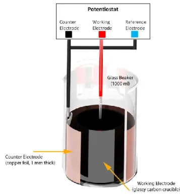
All polypyrrole substrates were electrochemically deposited onto conductive substrates according to the recipe developed by Yamaura [10, 11]. Depositions occurred in a propylene carbonate solution of 0.05 M tetraethylammonium hexafluorophosphate (Sigma), 1% vol/vol water, and 0.05 M pyrrole (Sigma). All materials were used as received except pyrrole, which was distilled under vacuum immediately before use. Polypyrrole films used as actuators and sensors were grown on cylindrical glassy carbon crucibles (HTW Hochtemperatur-Werkstoe GmbH) as shown in Figure 1. Polypyrrole films used as supercapacitors were grown on gold-plated, glass microscope slides (EMF-Corp). The counter electrode for all depositions was a 0.5 mm thick sheet of copper foil (McMaster-Carr), whose surface area was at least 1.5 times the surface area of the working electrode.
Films were deposited galvanostatically deposited with a potentiostat at a current density of 0.5 A/m2 while being
maintained at a temperature of -40o C. Galvanostatic deposition
times ranged from 6 to 8 hours, resulting in film thicknesses near 15 µm. Films were air-dried for 12 hours after deposition. Polypyrrole films grown on glassy carbon crucibles were peeled off and cut to dimensions for use as actuators and length sensors. Polypyrrole films grown on gold-plated microscope
slides were kept on the growth substrates when used as supercapacitors.
Figure 1: Example setup for electrochemical deposition of polypyrrole. The volume between the working electrode and the counter electrode is filled with electrolyte solution and the pyrrole monomer. Films are galvanostatically deposited.
INSTRUMENTATION
Conducting Polymer Actuators
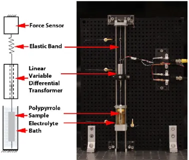
Polypyrrole actuator characterization was performed using a custom built apparatus that continuously monitored the force output and change in length of a polypyrrole actuator (Figure 2) while being excited potentiostatically. Polypyrrole actuator film samples were held in place using a miniature flexure clamp machined from blue-tempered 1095 spring steel and a gold-plated miniature alligator clip. The lower clip was fixed to a Teflon® beam that was mounted on the inside of an electrolyte bath. The upper flexure clamp was drawn by a 0.1 mm line of Spectra® cable, and held under tension by a compliant elastic band. The force output from the polymer under contractile conditions was calculated to be at least two orders of magnitude higher than the reaction force exhibited by the elastic band for the given operating range of displacements that the polymer might undergo during actuation, therefore creating quasi-isotonic testing conditions.
A 45 N force sensor (LSB200, Futek) was mounted above the elastic band, to monitor the tension in the system. The force sensor was also used to subject the polypyrrole actuator to
specific pre-stresses (~3 MPa) before each test. The force sensor was excited at 10 V and passed through a 100 Hz (cutoff) low-pass filter using a signal conditioning amplifier (2311, Vishay).
A DC/DC linear variable differential transformer (LVDT) (75S1DC-050SR, Sentech) was concentrically mounted between the upper flexure clamp and the elastic band. The core of the LVDT was attached to the non-elastic Spectra® cable, enabling any displacement produced by the actuator to be monitored. For tests in which the length sensor acted simultaneously with the actuator, the elastic band was replaced with an elastic, thin strip of polypyrrole.
Actuators were excited in an electrolyte-filled glass cylinder that was lined on the outer edges with gold-plated, 0.040 mm thick stainless steel foil. This foil served as the counter electrode during actuation tests. A silver wire placed near the actuator was used as the reference electrode.
Figure 2: Apparatus for quantifying actuation characteristics of polypyrrole actuators. The polypyrrole actuators are held under tension in a vertical configuration while being submerged in an electrolyte bath. A concentrically mounted LVDT measured the actuator displacements. For tests where an actuator and a length sensor operated simultaneously, the elastic band was replaced with a polypyrrole length sensor that served as the elastic restoring force of the actuator, while at the same time, measuring the actuator’s displacement.
The electrolyte into which conducting polymer actuators were submersed was the neat ionic liquid 1-butyl-3-methylimidazolium hexafluorophosphate (EMD Chemicals). Conducting polymer length sensors operated in air. Conducting
polymer redox supercapacitors were made by separating two polypyrrole substrates with an ionically porous membrane, and submersing the entire stack in a 0.3 M tetraethylammonium hexafluorophosphate propylene carbonate solution.
Actuators were excited in a three electrode configuration using a potentiostat (Amel 2053) whose input signal was computer-controlled by an analog output waveform from a National Instruments I/O data acquisition card (PCI 6289). A custom-built LabVIEW virtual instrument recorded the force output, LVDT output, input voltage and input current. All signals were sampled at 1 kHz.
ELECTROCHEMICAL METHODS
Polypyrrole redox supercapacitors were evaluated through various electrochemical techniques. Potentiostatic impedance spectroscopy characterization was performed over a broad frequency range (0.01 to 200 Hz) using 20 mV excitation. Specific capacitance, C, was determined by the equation:
𝐶 = 1
𝑍 ∗𝑓 , (1)
where Zim is the imaginary impedance and f is the frequency in Hertz.
Cyclic voltammetry tests sweeping from -1.0 V to 1.0 V were performed at 12.5 mV/s, 25 mV/s, 50 mV/s, and 100 mV/s. From the cyclic voltammograms, the capacitance of the sample was estimated by the equation:
𝐶 =𝑖
𝑠 , (2)
where C is the capacitance, i is the average current, and s is the scan rate [12].
Galvanostatic charge-discharge tests were performed at a current densities ranging from 0.5 to 2 mA/mg. From the galvanostatic charge discharge curves, the discharge capacitance Cd was determined using the equation:
𝐶𝑑= 𝑖∆𝑡
∆𝑉 , (3)
where i is the discharge current, and Δt/ ΔV is determined from the linear region of the discharge curve. The energy density was also determined from the charge-discharge curves by the equation:
𝐸 = 𝑖 ∫𝑉𝑑𝑡𝑚 , (4) where E is the energy density, V is the voltage drop, t is time and m is the mass of the polymer substrate. From the energy density, the power density, P, was also determined by
considering the ratio of the energy density E to discharge time Δtd as: 𝑃 = 𝐸 ∆𝑡 . (5) RESULTS Actuators
Frequency sweeps from 0.01 to 100 Hz were performed using sinusoidal excitation in a three-electrode electrochemical cell. The distribution of frequencies tested between 0.01 and 10 Hz was set up such that an entire sweep took approximately 30 minutes. For instances where a single frequency was tested more than once for a given sample, the peak-to-peak amplitude was determined by taking the mean peak-to-peak amplitude for each measurement at that frequency. The distribution of frequencies tested and the number of intermediate frequencies between each order of magnitude are shown in Table 1.
Start Freq. (Hz) Stop Freq. (Hz) Number of
Increments per Freq. Cycles
0.01 0.1 25 2
0.1 1 50 2
1 10 100 2
Table 1: Distribution of frequencies applied to polypyrrole actuators. Between a given start frequency and stop frequency, the number of increments indicates the number of discrete frequencies tested. If the cycles per frequency were greater than 1, then each discrete frequency was tested for that number of cycles.
After exciting polypyrrole actuators with a range of different frequencies, the data were processed by subtracting the mean position from the entire data set and converting the LVDT signal to a given displacement according the manufacturer’s calibration curve. Strain was determined by dividing the displacement of the actuator by the sample’s original length.
An example plot of the peak-to-peak strain over the entire frequency range is shown in Figure 3. Note that because the sweep was discrete, the lower frequencies are more easily distinguishable. A general trend is that the percent strain decreases as the excitation frequency increases.
Figure 3: Percent strain of polypyrrole actuator excited at frequencies ranging from 0.01 to 10 Hz.
A closer examination of the strain response at various frequencies shows a noticeable difference in the actuation characteristics of polypyrrole actuators as a function of frequency. Figure 4 shows the strain response of a polypyrrole actuator at a frequency of 0.01 Hz. The output actuation curve follows the sinusoidal shape of the input actuation voltage, with a peak-to-peak strain near 1.6%. For the frequency range tested with this sample, this is the largest observed strain.
Figure 4: Polypyrrole actuation curve at 0.01 Hz. The actuator’s response follows the input excitation voltage, characterized by a sinusoidal shape.
As the excitation frequency increases, the shape of the actuation curve becomes distorted with respect to the input sinusoidal waveform. Figure 5 shows the peak-to-peak strain of a polypyrrole actuator at 0.1 Hz. Already a large reduction in peak-to-peak strain is visible. The shapes of the lobes are also slightly flattened, following a distorted a sinusoidal pattern.
Figure 5: Polypyrrole actuation curve at 0.1 Hz. The actuator’s strain response is less sinusoidal at this frequency, and the peak-to-peak strain has decreased.
As the excitation frequency continues to increase, the strain decreases and the actuation curve becomes flatter. This is shown with an example polypyrrole actuator in Figure 6, where a polypyrrole actuator was excited with a 1 Hz sinusoidal input. After examining individual frequencies, the general trend of polypyrrole actuation as a function of frequency was determined by computing the peak-to-peak amplitude for each discrete frequency. Figure 7 shows this computed peak-to-peak strain for all of the frequencies examined. In this plot, the same polypyrrole actuator sample was used over the entire frequency range. The peak-to-peak percent strain shown in Figure 7 indicates that the actuation strain of polypyrrole decays steadily on a log strain log frequency scale for frequencies below 0.5 Hz. Above 0.5 Hz, the peak-to-peak strain decreases significantly faster. Near 2 Hz, the strain was outside the measurement capabilities of the instrumentation setup.
Figure 6: Polypyrrole actuation curve at 1 Hz. The actuator’s response approaches more of a square shape, while the peak-to-peak strain continues to decrease.
Figure 7: The peak-to-peak strain of a polypyrrole actuator when subject to ± 1.0 V sinusoidal excitation. The plot shows a moderate decay at low frequencies (less than 0.5 Hz) and a steeper decay as the frequency increases (greater than 0.5 Hz).
Length Sensors
Polypyrrole length sensors were evaluated by subjecting thin strips of polypyrrole films to strain ramps and sinusoidal strain inputs using a thin film dynamic mechanical analyzer previously described [12].
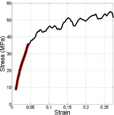
Dry polypyrrole films typically have an elastic modulus near 800 MPa and tensile strengths as high as 150 MPa [3]. Figure 8 shows a typical stress-strain curve for a polypyrrole film subject to a time-linear ramp in strain, at a rate of 0.1 %/s. For this particular sample (20 mm x 3 mm x 0.015 mm), the elastic modulus was 795 MPa. The linear-elastic region of polypyrrole, highlighted in red, occurs over a range in strain of less than 5%. Above 5%, polypyrrole films begin to permanently deform, as indicated by the change in slope of the stress-strain curve.
Figure 8: Stress-strain curve of polypyrrole film. Film sample was 3 mm x 20 mm x 0.015 mm.
By simultaneously monitoring the change in resistance of the polypyrrole sample as it is subject to strain, the piezoresistive characteristics of polypyrrole can be estimated and the gage factor, GF, of the material can be determined. The gage factor is estimated using the equation:
𝐺𝐹 =∆𝑅/𝑅
𝜀 , (6)
where ΔR is the change in resistance of the polypyrrole sample,
RG is the original resistance of the polypyrrole sample, and ε is
the strain that the sample undergoes. From Figure 9, the gage factor can be determined using Equation 6. For this particular sample, the gage factor was near 4.
Figure 9: Change in resistance of polypyrrole sample when subject to the strain curve shown in Figure 8.
Figure 10: Peak-to-peak change in resistance of polypyrrole length sensor subject to a 2% sinusoidal input strain at frequencies from 0.01 to 30 Hz.
Figure 11: Example change in resistance for a 1 Hz sinusoidal input.
Figure 12: Example change in resistance for a 10 Hz sinusoidal input.
The change in resistance of polypyrrole length sensors subject to a given strain input was also evaluated over the same range of frequencies at which the polypyrrole actuators were subject to. Due to a significant amount of noise in the system, the average strain value fluctuated significantly over time. The change in resistance for a 2% strain, sinusoidal input, had a peak-to-peak value near 0.25 Ω over the entire frequency range (Figure 10). The amount of noise for a given frequency and the
piezoresistive response at different frequencies can be seen in Figure 11 and Figure 12.
Energy Storage
Impedance spectroscopy plots of polypyrrole sample excited at 20 mV showed capacitance values on the order of 105
F/kg. The samples showed capacitive behavior, indicated by -90o phase, at frequencies below 0.01 Hz and resistive behavior
at higher frequencies (data not shown). A series of cyclic voltammetry tests were also performed on polypyrrole supercapacitors at various scan rates. Scans were performed between ± 1.0 V, close to the oxidation potential of polypyrrole [3]. The capacitance values from the cyclic voltammograms, calculated from Equation 2, are shown in Table 2. A slight increase in capacitance is visible as the scan rate is reduced. This is commonly observed with electrochemical redox supercapacitors. Scan Rate (-1.0 V to 1.0 V) Capacitance · 104 (F/kg) 100 mV/s 2.07 50 mV/s 2.24 25 mV/s 2.35 12.5 mV/s 2.45
Table 2: Specific capacitance of polypyrrole supercapacitors at scan rates ranging from 12.5 mV/s to 100 mV/s. Specific capacitance values were determined using Equation 2, and dividing the system's capacitance by the mass of the active material, polypyrrole.
Galvanostatic charge-discharge tests were used to estimate the lifetime of the polypyrrole supercapacitors. Figure 13 shows a comparison of the charge-discharge behavior for the same polypyrrole supercapacitor at the beginning of testing and near the 1000th cycle. The curve still retains its linear charging
characteristics over the number of cycles tested, but a slight decrease in the time it takes to complete a charge-discharge cycle is apparent as the number of cycles increases. The initial voltage drop, visible when the charging polarity switches, is an indication of the capacitor’s internal resistance. From Figure 13, the internal resistance does not change significantly over the first 1000 cycles.
The specific discharge capacitance of the system was estimated from the charge-discharge curves using Equation 3, as shown in Figure 14. From this figure, a slight decrease in specific discharge capacitance is visible during the first 300 cycles, after which the capacitance decays more slowly with cycle number. In this particular plot, the specific capacitance
was reduced to 94% of its original value after the first 3500 cycles. The energy and power densities were also computed from galvanostatic charge-discharge testing. The upper and lower discharge capacitance values for the current densities tested are shown in Table 3. The energy densities and power densities were computed from the discharge curves usings Equations 4 and 5.
Figure 13: Charge-discharge characteristics of a polypyrrole supercapacitor at the very beginning of testing and after 1000 cycles. Except for a slight decrease in the time it takes to charge and discharge, the charging characteristics remains unchanged. Current Density (mA/mg) Discharge Capacitanc e at 1.0 V; ( ·104 F/kg) Energy Density (kJ/kg) Power Density (kW/kg) Coloumbic Efficiency (%) 0.54 1.81 18.10 0.73 74 2.17 1.39 13.87 3.49 56 Table 3: Discharge capacitance, energy density and power density values for the range of current densities tested.
Figure 14: Specific capacitance of polypyrrole supercapacitor over 3500 cycles. A slight decrease in capacitance is visible during the first 300 cycles, after which the specific capacitance decays more slowly.
As a general trend, as the discharge current density increased the energy density decreased, the coloumbic efficiency decreased, and the power density increased.
Multifunctional Polypyrrole System
After evaluating each individual component made from polypyrrole, three functionalities of conducting polymers were combined to form a simultaneously operating, multifunctional system. An array of polypyrrole supercapacitors, each charged to 1 V were used to excite a polypyrrole actuator. At the same time, a polypyrrole length sensor was placed in series with the polypyrrole actuator, such that it measured any actuation displacement. Plots monitoring the input voltage and current from the polypyrrole supercapacitor, along with the actuator’s displacement and response from the polypyrrole length sensor are shown in Figure 15.
The response of the polypyrrole supercapacitor, after powering the polypyrrole actuator, approaches that of an ideal power source. A small amount of time dependent loading is visible (Figure 15 C), indicated by the slope of the voltage curve after an applied step. The strain response of the actuator was near 0.5% over a period of 10 seconds. With a longer excitation time or a higher voltage, this strain was observed to increase.
Figure 15: Multifunctional polypyrrole system. (A) Polypyrrole actuator powered by polypyrrole supercapacitors. Voltage (C) and current (D) output of polypyrrole supercapacitor. (D) Polypyrrole length sensor measuring polypyrrole actuation.
Due to the high power density of polypyrrole supercapacitors, the current response of the polypyrrole supercapacitor (Figure 15 D) looks similar to that of normal, potentiostatic excitation. An initial peak in the current is visible, caused by double layer charging [3].
The response of the polypyrrole length sensor (Figure 15 B) follows the strain output of the polypyrrole actuator (Figure 15 A) to a reasonable degree. Noise in the system, observed during independent length sensor testing, is apparent in the coupled, multifunctional system as well.
DISCUSSION
The independent characterization of polypyrrole, used as an actuator, length sensor and supercapacitor shows these functionalities can be used both as individual components or in a cooperative system. The change in the strain output of polypyrrole actuators as a function of frequency can be attributed to the diffusion-limited behavior of polypyrrole. For example, the flattening of lobes at higher excitation frequencies indicates that the actuator does not reach its full actuation state before the excitation polarity is switched. While the frequency range of polypyrrole actuations is currently limited, improvements in chemistry and excitation methods will enable conducting polymer actuators to generate larger strains and faster actuation responses.Polypyrrole length sensors still exhibit a significant amount of noise over time, thereby limited their use in steady-state positioning applications. Their consistent change in resistance at low (0.01 Hz) and moderate (30 Hz) frequencies, indicates, however, that they may be employable as rate sensors, measuring rapid changes in length. Polypyrrole supercapacitors, when scaled to large masses, provide ample power for polypyrrole systems. Although the energy densities of polypyrrole supercapacitors are still relatively low, their high-power densities make them ideal for short bursts of power delivery.
Manufacturing processes are currently being developed to combine the various functionalities of polypyrrole into single-substrate multifunctional materials. In the future, conducting polymer-based multifunctional materials could be used in everything from consumer textiles to medical diagnostic equipment. The improvement in actuation, length measurement, energy storage, alongside the development of other conducting polymer functionalities, will be critical in pushing these possibilities forward.
ACKNOWLEDGMENTS
This work was supported in part by the Intelligence Advanced Research Projects Activity under Grant NBCHC080001.
REFERENCES
[1] J.T. South, R.H. Carter, J.F. Snyder, C.D. Hilton, D.J. O’Brien, and E.D. Wetzel, “Multifunctional Power-Generating and Energy-Storage Composites for U.S. Army Applications,”
Materials Research Society Symposium Proc., Vol. 851, 2004.
[2] Q. Pei, R. Pelrine, M.A. Rosenthal, S. Stanford, H. Prahlad, and R.D. Kornbluh, “Recent progress on electroelastomer artificial muscles and their application for biomimetic robots,”
Proc. SPIE, Vol. 5385:41, 2004.
[3] J. D.W. Madden, “Conducting Polymer Actuators,” Ph.D. Thesis, Massachusetts Institute of Technology, Cambridge, MA, 2000.
[4] M. Berggren, D. Nilsson, and N.D. Robinson, “Organic materials for printed electronics,” Nature Mater. Vol. 6, 3–5, 2007.
[5] I.W. Hunter and S. LaFountaine, “A comparison of muscle with artificial actuators,” IEEE Solid-State Sensor Actuator
Workshop, pp. 178-165, 1992.
[6] R.Z. Pytel, E. Thomas and I. Hunter, “Anisotropy of Electroactive Strain in Highly Stretched Polypyrrole
Actuators,” Chemistry of Materials, Vol. 18:4, 861-863, 2006. [7] A. Mazzoldi, D. De Rossi, F. Lorussi, E.P. Scilingo and R. Paradiso, “Smart textiles for wearable motion capture systems,”
AUTEX Res. J. Vol. 2:4, 2002.
[8] P. G. A. Madden, “Development and modeling of conducting polymer actuators and the fabrication of a conducting polymer based feedback loop,” Ph.D. Thesis, Massachusetts Institute of Technology, Cambridge, MA, 2003. [9] B. Muthulakshmi, D. Kalpana, S. Pitchumani, and N. G. Renganathan, “Electrochemical deposition of polypyrrole for symmetric supercapacitors,” Journal of Power Sources 158: 2, 2006.
[10] M. Yamaura, K. Sato, T. Hagiwara, and K. Iwata, “Memory effect of electrical conductivity upon the counteranion exchange of polypyrrole films,” Synthetic Metals, 48: 3, 1992.
[11] T. Hagiwara, M. Hirasaka, K. Sato, and M. Yamaura, “Enhancement of the electrical conductivity of polypyrrole film by stretching: Influence of the polymerization conditions,”
Synthetic Metals 36:2, 1990.
[12] B.E. Conway, “Electrochemical supercapacitors: Scientific fundamentals and technological applications,” Kluwer Academic/Plenum Publishers, 1999.
[13] P. V. Pillai, and I. W. Hunter. “Stochastic System Identification of the Compliance of Conducting Polymers,”