HAL Id: hal-02042297
https://hal.archives-ouvertes.fr/hal-02042297
Submitted on 20 Feb 2019
HAL is a multi-disciplinary open access
archive for the deposit and dissemination of
sci-entific research documents, whether they are
pub-lished or not. The documents may come from
teaching and research institutions in France or
abroad, or from public or private research centers.
L’archive ouverte pluridisciplinaire HAL, est
destinée au dépôt et à la diffusion de documents
scientifiques de niveau recherche, publiés ou non,
émanant des établissements d’enseignement et de
recherche français ou étrangers, des laboratoires
publics ou privés.
Detection of Generic Micro-architectures on Models
Cédric Bouhours, Hervé Leblanc, Christian Percebois, Thierry Millan
To cite this version:
Cédric Bouhours, Hervé Leblanc, Christian Percebois, Thierry Millan. Detection of Generic
Micro-architectures on Models. PATTERNS 2010, The Second International Conferences on Pervasive
Pat-terns and Applications, Nov 2010, Lisbon, Portugal. �hal-02042297�
See discussions, stats, and author profiles for this publication at: https://www.researchgate.net/publication/230660675
Detection of Generic Micro-architectures on Models
Conference Paper · November 2010
CITATIONS 2
READS 70 4 authors:
Some of the authors of this publication are also working on these related projects: Ada Persistance View project
NEPTUNEView project Cédric Bouhours
Université Clermont Auvergne
21PUBLICATIONS 70CITATIONS
SEE PROFILE
Hervé Leblanc
Institut de Recherche en Informatique de Toulouse
32PUBLICATIONS 175CITATIONS
SEE PROFILE Christian Percebois
Institut de Recherche en Informatique de Toulouse
32PUBLICATIONS 82CITATIONS
SEE PROFILE
Thierry Millan
Paul Sabatier University - Toulouse III
21PUBLICATIONS 49CITATIONS
SEE PROFILE
All content following this page was uploaded by Cédric Bouhours on 29 November 2016.
Detection of Generic Micro-architectures on Models
Cédric Bouhours, Hervé Leblanc, Christian Percebois, Thierry Millan
IRIT – MACAO team – University of Paul Sabatier 118 Route de Narbonne
31062 TOULOUSE CEDEX 9 FRANCE {bouhours, leblanc, percebois, millan}@irit.fr
Abstract— Existing pattern detection methods generally use
code information obtained during reengineering process. However, none of these methods exclusively works with design information. In this paper, we propose a novel pattern detection method based on structural properties of UML models. This technique allows the detection of any kind of generic micro-architecture, like design patterns or spoiled patterns. Since a generic architecture is context-free, the structure of the searched fragments depends on the use context. So, our technique uses a structural concordance paradigm to identify all possible instantiations of a generic micro-architecture. To increase the precision of the detection, authorized, prohibited, and optional relations can be directly precised into the micro-architecture model.
Keywords- Pattern detection. Graph isomorphism. UML Model.
I. INTRODUCTION
Various works aim at identifying fragments representing correct, incorrect or incomplete instantiations of design patterns, in order to help the comprehension of existing designs and to provide a base for possible improvements [1]. To identify characteristic fragments, it is necessary to parse models, to ensure that the execution time of the algorithm is adapted to consequent models and to recognize a form that is approximate or to supplement. This approximation is very problematic, because it introduces uncertainties into the research. In the case of design patterns, the designer adapts the pattern to his problem, obliging the detection methods to be able to detect every possible form [2]. To render possible these detections, some tools use source code to identify complete or distorted versions of design patterns [3]. The information extracted from the source code augments the precision of fragment intent and so the pattern detection.
However, during model-driven processes, the
identification of patterns concerns the designer in order to target specific model fragments. For example, spoiled patterns allow the detection of fragments substitutable with design patterns before a coding stage [4]. Thus, we have conceived a detection method based on UML structural properties of UML models. Thanks to this method, we are able to identify instantiations of generic micro-architectures, like design patterns or spoiled patterns. The first intent of our detection method concerns the detection of spoiled pattern, which we present in Section 2. Section 3 presents the model representation we use to formalize our detection technique, and takes a stand on our work in relation to existing graph matching problems. The remainder of the paper is composed by the techniques used to compute the detection (Section 4), and some validation tests in Section 5.
The paper ends with a discussion of related works and a conclusion, in Sections 6 and 7. The main contributions of this paper are the specification and the implementation of a generic UML graph matching method able to detect pattern instantiations whatever their form.
II. SPOILED PATTERN DETECTION
Choosing a good design pattern and ensuring the correct integration of the chosen pattern are non trivial for a designer who wants to use them. To help designers, we propose design inspection in order to detect “bad smells in design” and models reworking through use of design patterns. The
automatic detection and the explanation of the
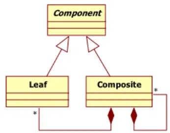
misconceptions are performed thanks to spoiled patterns [4]. If we consider that a design pattern is the optimal reusable micro-architecture for a type of problem, then for each design problem that is solvable with a design pattern, the optimal solution is the instantiation of the design pattern. Moreover, if we consider an alternative solution as a valid solution but with a different architecture compared to the optimal solution, then, an alternative solution is an inadequate solution for a given problem, and is substitutable with the instantiation of the concerned pattern. A spoiled Composite pattern is given in Fig. 1.
Figure 1. A spoiled pattern (development of the composition on Composite) Each spoiled pattern has a name that describes the misconception: here the development of the composition link on the composite participant of the pattern. So, there is not a maximal factorization of the composition which implies addition or removal of a leaf or a composite need code modification.
Structurally, a spoiled pattern is represented at the same level of granularity as a design pattern allowing us to identify them as design patterns. An alternative fragment is a model fragment such as its structural properties match with the structural properties of a spoiled pattern and whose intent conforms to the corresponding pattern. Then, after the detection, an alternative fragment can be considered as potential. The validation of its intent is assumed by the
Component
Leaf Composite
*
designer of the user model. More details on these concepts, especially the collect, the catalog, the use in a tooled design review activity, and the refactorings can be found in [12].
The static UML model in Fig. 2 represents a basic architecture for a file system management. Authors of this model are interested in the presentation of some object concepts: inheritance between classes (a uniform protocol for every FileSystemElement is encapsulated by a corresponding abstract class) and management of reference and delegation (there are composition links between container and components).
Nevertheless, this model contains a misconception. Although there is a uniform protocol owned by the class FileSystemElement, the composite links management along a hierarchical structure is duplicated. Indeed, the Directory class manages independently links on Files and Directories.
{Directory, File, FileSystemElement} is an exact
instantiation of the Composite spoiled pattern. It is easy for the designer to see that this fragment has the same intent as the Composite pattern and to consider it as a bad smell in design. Furthermore, when the authors have implemented this model, they realized that there were defects. They adapted their code to correct them, without changing the design model. Therefore, the fragment must be substituted with the instantiation of the composite pattern on the user model or context.
Figure 2. A File System Management Design
During a process development, it is more interesting to detect bad smells in design before the coding stage. Indeed, the model correction is easier and uses less time if the code is not already written. So, we have conceived a detection technique working with design information, and without information issued from reverse engineering process. The existing techniques use code information issued from their own reversion methods.
As a spoiled pattern has the same abstraction level as a design pattern, we consider that they are both “pattern” and so “generic micro-architecture”. Our detection technique is able to detect generic micro-architecture, and so, the remainder of this paper uses “pattern” term to mean “design pattern”, “spoiled pattern” or “generic micro-architecture”. For the sake of clarity, we use the Composite design pattern as an example.
III. GRAPH REPRESENTATION
We consider models described in UML 1.5 [5] according to the XMI standard [6]. With this meta-model, models can be represented by directed graphs. A graph consists of typed nodes representing the classes and the relations between them. Arrows are used to indicate the direction of the relations between classes. In our case, we are interested by classes, associations, and generalizations only. There is a gap between the visualization and the internal representation of a UML model.
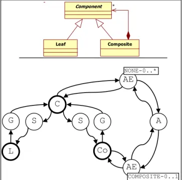
Fig. 3 illustrates these two representations in UML 1.5 for a design pattern: in a class diagram and in a graph conforms to XMI format. In this example, the design pattern is a simple directed graph, with the vertices C, L and Co, respectively Component, Leaf and Composite. There are also sets of vertices {A}, {AE}, {G} and {S}, respectively
Association, AssociationEnd, Generalization and
Specialization of the UML meta-model.
We have separated the vertices in two different subsets:
Vc containing all the classes of the model, and Vm containing
all the meta-classes allowing the connections of the classes. The vertices of the set {AE}, for AssociationEnd, come from the meta-model and are used to connect Classifier to Association. These vertices are tagged by AssociationEnd meta-class attributes in order to characterize the extremity of associations. For example, for the vertex Co, the adjacent vertices are AE, G and S only, excluding A which is accessible from AE only.
Figure 3. A UML model and its directed graph representation As we consider UML models as graphs, we can formulate our patterns identification problem as a problem of sub-graphs or directed sub-graphs identification in a graph. There are two main approaches in this domain. The first one is known as exact graph matching, which consists in finding exactly a given subgraph in a graph [7]. The second
C
Co
L
S
G
S
G
A
AE
COMPOSITE-0..1AE
NONE-0..* Component Leaf * Composite Directory +open() +delete() +getSize(): int +getAbsolutePath(): String +add(e: FileSystemElement) +remove(e: FileSystemElement) +get(): FileSystemElement[*] +searchDir(name: String) +searchFile(name: String) File -size: int -data: byte +open() +delete() +getSize(): int +getAbsolutePath(): String FileSystem +getRoot(): Directory +setRoot(d: Directory) FileSystemElement +delete() +getSize() +getAbsolutePath() +open() Path -path: String +getPath(): String +getParts(): String[*] Nameable -name: String -getrName(): String * -root -subdirectory * FileSystemServices+search(p: Path): FileSystemElement
Comparable
approach consists in identifying all the sub-graphs looking like more or less a given graph [1] and is called inexact graph matching.
Exact graph matching algorithms require the examination of all possible sub-graphs that have the same number of nodes and arrows with the source graph, which means a NP-complete problem [7]. For our problem, exact pattern matching algorithms are inefficient. As a pattern is a generative base of a family of specific designs, we do not exactly search the generic micro-architecture, but one of its instantiations, which are not known in advance.
Inexact graph matching algorithms are very useful when an isomorphism between two graphs cannot be found or is too strict for research. They find the best correspondence between two graphs. For example, some algorithms calculate the distance between two graphs, expressed for instance in number of modifications to transform a graph to the compared graph [1]. In the context of pattern detection, such algorithms are more interesting, because they are able to detect sub-graphs structurally close to the pattern. However, it is not sufficient, because a given design pattern may have several forms depending on the instantiation context.
Since we cannot use exact or inexact pattern matching, we have defined a detection method working by structural concordances. Thanks to structural properties allowing the structural detection of pattern, this technique is able to detect pattern instantiations, whatever their form, and taking into consideration authorized, prohibited or optional relations between classes, as described in section 3.3.
IV. SPECIFICATION OF THE DETECTION
A pattern is described with a set of structural properties allowing its structural description, and thus the detection of its instantiation in a model. We have decomposed the remarkable properties into two subsets: the local properties that characterize individually each class and the global properties which characterize the classes against each other depending on their inter-relations. This separation allows us to constitute different filters during the detection, through use of structural similarity comparisons. The result of the search is a set of fragments identified in the model analyzed. A. Structural Concordance
The structural properties of a pattern enable us to detect fragments in models. Compared to graphs, they enable us to detect sub-graphs families, because they describe the patterns as well as the fragments they can generate. Our detection method uses the local and global structural properties to check the structural concordance of the fragments with the patterns.
Definition 1 presents in a formal way a model m. As seen previously, it is a directed graph with two sets of vertices Vc and Vm, respectively representing the model classes and the instances of meta-classes describing the relations between the classes.
(1)
Like for a model, we formally define a pattern in definition 2.
Each pattern has a unique reference participant which we note reference_dp. It represents a particular vertex of Vcdp that we detail in part B. This vertex is chosen by an oracle according to its structural complexity and its responsibilities on the problem to solve.
(2)
Thus, we have two directed graphs where we search for combinations of occurrences of the first in the second. In order to avoid a combinatorial explosion of the research possibilities, and thus to limit the problem complexity, we do a first filtering of the sets of the vertices having the adequate local properties.
The first step consists in searching for all the vertices of graph m in accordance with the predicate 5 local_SPC. This predicate, meaning “structural properties concordance”, allows to check if a vertex c of the graph m has, at least, the same adjacent vertices as a vertex p of dp. Thus, if c is
local_SPC with p, the class corresponding to c has, at least,
the same local structural properties as the participant of the pattern corresponding to the vertex p. The comparison between the adjacent vertices is done with an equivalence relation comparing the type and the attributes of the adjacent vertices, as definition 3 shows it, with a constraints relaxation presented in part 3.3.
(3)
By extension, we obtain the definition 4.
As the adjacent vertices of a vertex of Vc belong to Vm and as all the vertices Vm are strongly typed, the vertices of
Vc can be filtered thanks to their local properties, as
predicate 5 shows it.
(5)
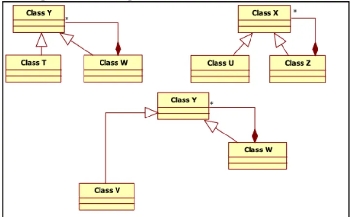
In order to illustrate the predicate local_SPC, we search Composite design patterns in the model of Fig. 4, whose local properties of each participant are illustrated in Fig. 5. The result of the application of the predicate local_SPC is illustrated in Table 1. For more legibility, the models are represented in UML.
Figure 4. A model example
Figure 5. Local structural properties of the Composite design pattern TABLE I. RESULT OF THE PREDICATE LOCAL_SPC ON THE MODEL
Class
local_SPC R T U V W X Y Z
Composite OK OK
Component OK OK
Leaf OK OK OK OK OK
The classes marked in Table 1 validate predicate
local_SPC with the corresponding participant. It is possible
to notice that the classes have the same adjacent vertices as their participants, except for classes Y, W and Z which have more. For example, we can note that the class Y has three daughters. It is partly thanks to the fact that a vertex of Vc can have more adjacencies, that we can detect all the various possible pattern instantiations. Moreover, we can notice that class W and class Z validate the predicate on two different participants from the pattern, Leaf and Composite. Indeed, the local properties of Leaf are included in those of Composite. Without the global properties, we cannot differentiate the Composite classes from the Leaf classes yet.
After comparing all the vertices of Vcdp with all those of
Vcm, i.e. all the participants of the pattern with all the classes of the model to analyze, we obtain a set of vertices having their adjacent vertices at least identical to those of the participants of the pattern. This first predicate is used as filter on the sets of the vertices of m.
Predicate 6 global_SPC allows to check the concordance of the global properties, i.e. if a subgraph sf of m is isomorphic to dp.
(6)
A sub-fragment global_SPC with dp has, by definition, the same number of vertices as the pattern. Although the instantiation of the pattern causes the multiplication of some vertices, all the combinations, such as each class represents a distinct participant, remain isomorphic with the pattern. Fig. 6 illustrates this isomorphism of the sub-fragments of the model presented in Fig. 4.
Figure 6. Sub-fragments of Fig.4 isomorphic with the pattern of Fig. 3 In the model of Fig. 4, according to the vertices identified as being local_SPC with the vertices of the pattern, we can build only three sub-fragments in conformity with global_SPC. For example, the combination class U, class W and class Y, is not a sub-fragment, because even if there is the same number of vertices as in the pattern and each vertex is local_SPC with a vertex different from the pattern, there is no isomorphism between this combination and the pattern.
Thus, the predicate global_SPC enables us to eliminate class W and class Z from the Leaf responsibilities, since it is not possible to build a combination of classes in conformity with the predicate global_SPC with one of these classes to the responsibilities of Leaf.
Now, we have to build the complete fragments, i.e. to couple the sub-fragments which share the same vertices. A complete fragment cf is a subgraph of m including at least an isomorphic sub-fragment with the pattern and such as any graph induced by a combination of vertices referring once each participant of the pattern remains isomorphic with the pattern. Moreover, only one vertex of cf, that we name
reference_class, is local_SPC with reference_sp, the
reference vertex of the pattern. In the case of Fig. 6, if we
Class X Class U Class Z * Class Y Class W Class T * Class Y Class V Class W * Component Leaf * Composite Component Leaf * Composite Component Leaf * Composite Class X
Class U Class Z Class Y
Class V Class T Class W
*
*
consider that Composite is the reference participant, we can regroup the sub-fragments {ClassY, ClassT, ClassW} and {ClassY, ClassV, ClassW} to form a complete fragment.
Thus, the predicate 7 complete_fragment allows to check if a fragment cf is a set of sub-fragments, each one isomorphic with dp. (7)
The application 8 participant associates to each vertex of the fragment cf, a vertex of the pattern such as it is in local concordance and which it is connected in the same way to the reference participant.
In proceeding like that, we can build fragments representing all the possible instantiations of the pattern. Indeed, even if it is not possible to anticipate which form has a complete fragment, it is sure, whatever its form, that it is composed of isomorphic sub-fragments to the pattern, since all the possible complete fragments will always have their classes connected in the same way to the respective participants of the pattern.
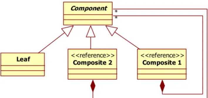
Fig. 7 presents two fragments with isomorphic sub-fragments to a pattern.
Figure 7. Two fragments with isomorphism sub-fragments to the Composite design pattern
The sub-fragments of the left fragment are {Composite, Component1, Leaf} and {Composite, Component2, Leaf}. Those of the right fragment are {Composite, Component1, Leaf1}, {Composite, Component2, Leaf1}, {Composite, Component1, Leaf2} and {Composite, Component2, Leaf2}. Thus, it is possible to notice that the two fragments presented are two different instantiations, but recognized as complete fragments.
A particular case is presented in Fig. 8.
Figure 8. A particular case of a complete fragment
The two sub-fragments of this model are isomorphic to the Composite pattern: {Composite1, Component, Leaf}, {Composite2, Component, Leaf}. However, if we analyze this case, we can wonder whether, except its structure, it constitutes a true complete fragment. Indeed, the composite participant are not linked between them. Thus, we propose that Fig. 8 presents two distinct fragments {Composite1, Component, Leaf} and {Composite2, Component, Leaf}. We do not authorize a fragment to have two classes having the Composite responsibilities. We named this additional characteristic the “reference participant”, necessary to the representation of the results of detection and the limitation of the matching complexity.
B. Reference Participant
Each participant of a pattern has not the same importance in the intent aimed by the pattern. The fact that a design pattern is the best solution resides in its structural organization, obligatory support with any collaboration between objects. For the Composite pattern, take into consideration the UML models presented in Fig. 9 and try to answer the question: can these models be still regarded as instantiations of the Composite pattern?
Figure 9. The Composite pattern without Composite and without Leaf If we remove all the occurrences of the Leaf participant of the pattern, we do not loose the intent of the pattern, even if we lose the possibility of adding terminal elements in the hierarchical tree of composition. But, if we remove all the occurrences of the Composite participant, no more composition is possible. Indeed, it is Composite which completely manages the responsibilities for the composition of the objects, first intent of the pattern. Thus, this participant plays a dominant role in the pattern.
The reference participant depends on the pattern concerned. This participant is manually chosen with the heuristic evaluating its essentiality with the number of structural properties of each class.
Component * Composite Component Leaf Component Leaf * Composite 1 <<reference>> * Composite 2 <<reference>> Component 1 Composite <<reference>> Leaf * * Component 2 Component 1 Composite <<reference>> Leaf 1 * * Component 2 Leaf 2 (8)
C. Authorized, Prohibited or Optional Relations
Any class not having the responsibilities of the reference participant can be found multiplied in the fragment, whereas those marked reference are separate in different fragments. But what does occur if a class of the fragment is connected of more than another way that envisaged? Fig. 10 illustrates this case on a fragment.
Figure 10. A model fragment with one supplementary relationship If we apply the method introduced previously, the fragment is detected, because it respects strictly the structural properties of the Composite pattern. However, the additional inheritance modifies the responsibilities of the classes concerned. A Leaf inheriting a Composite does not have a meaning in the hierarchical composition of objects, since a terminal object cannot be a specialized non-terminal object. Thus, we discriminate any fragment having connections invalidating the intent of a pattern.
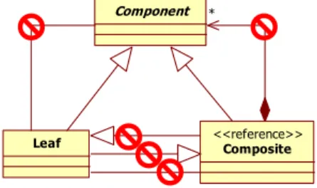
To recognize which relations of the fragment are discriminating, we documented the pattern with information indicating which connections are optional, obligatory or prohibited. This documentation is done thanks to a UML profile allowing us to add specific information on relationships. Fig. 11 illustrates the Composite profiled pattern.
Figure 11. A graphical representation of the profiled pattern Reported to the graph, we supplement the description of the pattern with a graph of the prohibited relations, comparable to the “Negative Conditions Application” (NAC) of graphs grammars [8]. If a connection appears in the graph of the pattern, it must obligatorily be present in the fragment; if it appears in the graph of the relations prohibited, it must absolutely miss in the fragment. If a connection is present in the fragment, but absent from the two other graphs, it is regarded as optional and neutral for detection. Thanks to this complement, we can now, besides detecting all possible forms of instantiation of the pattern, refuse certain forms which we suppose bad for the intent of the fragment.
D. Genericity of the Detection
Our generic detection algorithm is decomposed into three steps (local_SPC, closure form the reference participant,
global_SPC). At the end of each step, a set of characteristic
classes is selected from the set resulting from the preceding step. The first step consists in classifying all classifiers of the model to analyze according to local structural properties of each participant of the pattern. The second step consists in computing potential fragments according to the paths between the reference participant and the others participants of the pattern. The third step consists in verifying the global conformance on the potential fragments and to pinpoint complete fragments. Then the structure of the algorithm is flexible and does not depends on the structure of the pattern to retrieve. The genericity of our approach is provided by an automatic queries generator using profiled patterns. So, to detect a new pattern, it is sufficient to profile it and to generate its query [12].
We chose OCL to encode our detection queries. OCL is a language of constraints used to add semantics into UML models [9]. The Neptune platform was developed by our team within the European Neptune project [10]. The OCL interpreter proposed by the platform implements the standard OCL 2.0 [9] and two extensions of OCL [11]. The second relates to the queries which can return a result of any type of the meta-model, which introduces the concept of view. We use this capacity to carry out our search for complete fragments in a model. Moreover, thanks to the navigational property of OCL, the generation of the queries consists in navigating in the meta-model of the pattern to detect. In following the three steps of the algorithm and in considering the pattern as a graph, the generator analyzes all the possible paths between each vertex and transforms them in an OCL query.
V. VALIDATION
In order to validate the detection algorithm we have sought models of real projects. We would like recall here that we search model fragments at design level without any information from the code. Unfortunately, we did not find industrial projects with exploitable models for our needs; the percentages of association links on inheritance links are too low. So, we have used the code of free projects to obtain reversed models. To do so, we used the Java reverse module of ArgoUML.
The problem with code reversion relates to associations between classes. It is very difficult for reverse softwares to know which variable must be regarded as attribute, association, composition, etc. However, the module of ArgoUML makes it possible to impose that all the attributes are transformed into associations. To take into consideration the parameterized genericity of the latest versions of Java, we have added in the ArgoUML module the capacity to convert these types into (1..n) associations. Thanks to this modification, we consider that the reversed models have a good abstraction level.
In order to make sure of the validity of our detection
algorithm, we sought fragments corresponding to
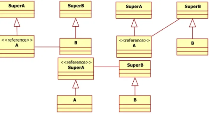
characteristic architectures. Fig. 12 presents the fragments that we have searched in nine models (ArgoUML, JUnit, JFreeChart, JabRef, Jena, AWT, JHotDraw, JRefactory, and Neptune). We can notice that these fragments are the Bridge
Component Leaf * Composite <<reference>> Component Leaf Composite *
pattern and its alternatives. In order to precise the detection, we have searched the same fragments twice: first, with information about authorized and prohibited relations, and second without any complementary information. For these examples, all supplementary relations between classes are prohibited.
Figure 12. The searched fragments
To validate the queries generated for these micro-architectures, we have executed them directly on the models allowing the generation of the queries. All queries are able to detect the model which has permitted their generation. So, we can say that we detect, at least, the minimal micro-architecture with exact instantiation.
The results obtained at the end of the detection show that all possible instantiations have been identified in the models, and no more. You can see the OCL queries generated corresponding to each pattern of Fig. 12 on [20]. It is interesting to notice that all fragments are identified twice: {SuperA, A, B, SuperB}, and {SuperB, B, A, SuperA}. The result is correct; each structure pattern is symmetric. Moreover, the researches with information about authorized and prohibited relations have retrieved fewer fragments than with the fragment without complementary information.
VI. RELATED WORKS
We present three generic detection techniques used in a similar context. The first two concern approached identifications of design patterns for re-documentation, and the third concerns exact identification of design problems solvable by design patterns.
Patterns identification by comparison of similarities. [1] proposes an algorithm for approximate pattern matching based on comparisons of similarities. This algorithm generates, from two graphs encoded by a matrix, an adjacency matrix representing the closeness of these two graphs. Matrix representations of relationships between artifact developments are used to compute effective approximations. Another way to represent UML models is to consider their visual forms as multi-graphs. Each type of relationship is represented by a different graph. A designer can choose on what information the similarity search is based (associations, generalizations, method specializations, method invocations, etc.). Thus, for a model and a pattern, the average of weighted matrices results for each significant input matrix (associations, generalizations, methods, etc.) is computable. The weighting is determined by the designer
according to the importance it wishes to provide the various relationships of a static UML model. This weighted average is then the likeness of a fragment from a design pattern.
Patterns detection by fuzzy evaluation of UML models. Fujaba (From UML to Java And Back Again) is a tool that can generate Java code from a UML model and impact code changes on this model [13] [14]. A component of automatic detection of design patterns has been added. This component uses Abstract Syntax Graphs (ASG) [15] to describe a model by eliminating most syntactic variants and formatting problems. Design patterns are decomposed into sub-patterns implemented as rules of graph transformation. However, if some sub-patterns are generic, eg. all possible ways to assign a value to an attribute in a method, the detection algorithm cannot detect patterns whose shape is not really the sub-assembly patterns provided. To overcome this limit, fuzzy evaluation mechanisms have been proposed by S. Wenzel [2]. They can detect patterns used differently than what is recommended, as well as incomplete patterns. To detect patterns in UML, it is necessary to describe a combination of roles in the UML sense. A role corresponds to a meta-class, which can be attached to OCL constraints [9]. Constraints can describe the complex arrangements of certain patterns and clarify the internal organization of each role. Using this mode of representation, it is possible to detect design patterns in the same manner as a "cast of theater" [2]. The detection assigns a role in the pattern to some model elements. Each assignment is quantified by a value (0 to 100%) representing how the element can play the role. To get 100%, elements must have the same type as the role and respect each of the constraints described in the pattern. After the detection, the candidate fragments are presented to the designer. Implemented in a component of Fujaba, this technique detects target fragments "similar" to contextualization’s design patterns.
Problems detection by constraint propagation. El-Boussaidi and Mili [16] proposes to detect fragments consistent with the meta-model of the problem of a pattern, and replace fragments by instantiation of the corresponding patterns. This detection technique reformulates the problem of homomorphism of graphs proposed by M. Rudolf [17]. A CSP is defined by a finite set of variables in a domain, and a finite set of constraints specifying how values can be assigned to variables [18]. CSPs are generally used to solve efficiently backtracking algorithms. When a value is assigned to a variable, all the constraints of this variable are propagated to other variables. To construct a CSP dedicated to pattern matching, it is necessary to work with two graphs, one to search (the source graph) and one in which research is conducted (the target graph) [17]. Each vertex and each arrow of the source graph are associated with distinct variables. The domain of variable vertices and arrows correspond respectively to the set of vertices and arrows of the target graph. The constraints construction is done on the parameters compared to validate the research. H. Mili and G. El-Boussaidi [19] defines design patterns as a triple (MP, MS, T) where MP is the problem solved by the pattern, MS is the solution to the problem, and T is the transformation that converts MP to MS. MP and MS are respectively the
SuperA A <<reference>> SuperB B SuperA A <<reference>> SuperB B SuperA <<reference>> A SuperB B
meta-models of the problem and solution. When a designer discovers a fragment of his model conforms to the meta-model of the problem, he has only to apply the transformation rules for modifying the fragment.
TABLE II. SUMMARY OF APPROACHES
[1] [14] [16] us Do not perform preprocessing on the model
to analyse OK OK
Do not use information from the code OK Perform detection by successive steps OK OK OK Limit the execution time OK OK Limit the number of fragments identified OK OK Do not degrade the consensus of the pattern OK OK OK Detect all possible instantiations OK OK OK
Table 2 summarizes the specifics of our problem with the related works. The last column refers to our approach. We guarantee a technique for early detection, even on large models. It is not pertinent to test all the meta-classes of the model to analyze, and it is better to make a quick filter to restrict the number of comparisons. Then we work directly and without pretreatment with the patterns encoded as models. Moreover, a spoiled pattern constitute a base generating a family of possible instantiations, and we identify accurately all the fragments of the same family.
VII. CONCLUSION
We have presented a complete method to detect generic micro-architectures on models. Then, a major issue of our work is the fact that we have reasoned at design level uniquely. That implies to use information present in models only and to define a re-documentation technique for retrieve patterns in a model. We have used standards dedicated to model engineering: UML profile and OCL queries. From a profiled model representing the structure of a pattern, we deduce automatically the OCL query that permit to retrieve all authorized instantiations of this pattern in a design model.
The detection is the core part of a tooling design review activity [4]. We have implemented this activity into satellite software of the Neptune platform and we named it Triton [12]. As a code review permits to detect inconsistencies, no respect of coding rules, and bad smells in code before a production running, the design review permits to detect model fragments bad conceived and to refactor thanks to design patterns before a coding stage. The results of our queries are not too strict and not fuzzy; each detected fragment can be precisely built from a canonical form and by successive addition of participants. Therefore, we think that our detection method can be reused by the query part of any transformation model language.
However, the detection is based on structural properties only. For now, we have a catalog of spoiled structural design patterns. Dynamic views would be taking into consideration to detect behavioral design patterns and to precise some structural patterns by the detection of message exchange motifs.
REFERENCES
[1] N. Tsantalis and S. T. Halkidis, “Design Pattern Detection Using Similarity Scoring”, in: IEEE Transactions on Software Engineering, IEEE Press, volume 32, number 11, pages 896-909, 2006.
[2] S. Wenzel, “Automatic detection of incomplete instances of structural patterns in UML class diagrams”, in: Nordic Journal of Computing, Publishing Association Nordic Journal of Computing, volume 12, number 4, pages 379-394, 2005.
[3] H. Albin-Amiot, P. Cointe, Y.-G. Guéhéneuc, and N. Jussien, “Instantiating and Detecting Design Patterns: Putting Bits and Pieces Together”, in: proceedings of the 16th conference on Automated Software Engineering (ASE), IEEE Computer Society Press, pages 166-173, 2001.
[4] C. Bouhours, H. Leblanc, and C. Percebois, “Bad smells in design and design patterns”, in: Journal of Object Technology, ETH Swiss Federal Institute of Technology, volume 8, number 3, pages 43-63, 2009.
[5] Object Management Group., “Unified Modeling Language”, http://www.omg.org/spec/UML/1.5/PDF/index.htm, 2010.
[6] Object Management Group., “XML Metadata Interchange”, http://www.omg.org/technology/xml/index.htm, 2007.
[7] J. R. Ullmann, “An Algorithm for Subgraph Isomorphism”, in: journal of the ACM (JACM), ACM, volume 23, number 1, pages 31-42, 1976.
[8] A. Habel, R. Heckel, and G. Taentzer, “Graph grammars with negative application conditions”, in: Fundamenta Informaticae Journal, IOS Press, volume 26, number 3-4, pages 287-313, 1996. [9] Object Management Group., “Object Constraint Language”,
http://www.omg.org/cgi-bin/apps/doc?formal/06-05-01.pdf, 2006. [10] Neptune consortium, “Method, Checking and Document generation
for UML applications”, http://neptune.irit.fr/images/files/Neptune Book/407719ps.pdf, 2003.
[11] T. Millan, L. Sabatier, T. T. Le Thi, P. Bazex, and C. Percebois, “An OCL extension for checking and transforming UML Models”, in: proceedings of the 8th International Conference on Software Engineering, Parallel and Distributed Systems (SEPADS), WSEAS Press, pages 144-150, 2009.
[12] C. Bouhours, “Detection, Explications et Restructuration de défauts de conception : les patrons abîmés”, PhD, IRIT, 2010.
[13] FUJABA, From UML to Java and Back Again, http://wwwcs.uni-paderborn.de/cs/fujaba/projects/ reengineering/index.html, 2005. [14] S. Wenzel, “Detection of Incomplete Patterns Using FUJABA
Principles”, in: proceedings of the 3rd International Fujaba Days 2005 : MDD in Practice, pages 33-40, 2005.
[15] J. Niere, W. Schäfer, J.P. Wadsack, L. Wendehals, and J. Welsh, “Towards pattern-based design recovery”, in: proceedings of the 24th International Conference on Software Engineering (ICSE), ACM Press, pages 338-348, 2002.
[16] G. El-Boussaidi and H. Mili, “Detecting Patterns of Poor Design Solutions Using Constraint Propagation”, in: proceedings of the 11th international conference on Model Driven Engineering Languages and Systems (MoDELS), Springer-Verlag, volume 5301, pages 189-203, 2008.
[17] M. Rudolf, “Utilizing Constraint Satisfaction Techniques for Efficient Graph Pattern Matching”, in: selected papers from the 6th International Workshop on Theory and Application of Graph Transformations (TAGT), Springer-Verlag, pages 238-251, 2000. [18] F. Bacchus and P. Van Beek, “On the Conversion between
Non-Binary and Non-Binary Constraint Satisfaction Problems”, in: proceedings of the 15th National Conference on Artificial Intelligence (AAAI) and of the 10th Conference on Innovative Applications of Artificial Intelligence (IAAI), AAAI Press, pages 311-318, 1998.
[19] H. Mili and G. El-Boussaidi, “Representing and Applying Design Patterns: What Is the Problem?”, in: proceedings of the 8th international conference on Model Driven Engineering Languages and Systems (MoDELS), pages 186-200, 2005.
[20] http://www.irit.fr/~Cedric.Bouhours/Examples/
View publication stats View publication stats