HAL Id: hal-01740823
https://hal.sorbonne-universite.fr/hal-01740823
Submitted on 22 Mar 2018
HAL is a multi-disciplinary open access
archive for the deposit and dissemination of
sci-entific research documents, whether they are
pub-lished or not. The documents may come from
teaching and research institutions in France or
abroad, or from public or private research centers.
L’archive ouverte pluridisciplinaire HAL, est
destinée au dépôt et à la diffusion de documents
scientifiques de niveau recherche, publiés ou non,
émanant des établissements d’enseignement et de
recherche français ou étrangers, des laboratoires
publics ou privés.
Internet Acceleration with LISP Traffic Engineering and
Multipath TCP
Chi-Dung Phung, Matthieu Coudron, Stefano Secci
To cite this version:
Chi-Dung Phung, Matthieu Coudron, Stefano Secci. Internet Acceleration with LISP Traffic
Engi-neering and Multipath TCP. Innovations in Cloud, Internet and Networks (ICIN) 2018, Feb 2018,
Paris, France. �10.1109/ICIN.2018.8401586�. �hal-01740823�
Internet Acceleration with LISP Traffic Engineering
and Multipath TCP
Chi-Dung Phung, Matthieu Coudron
∗, Stefano Secci
Sorbonne Universit´es, UPMC Univ Paris 06, UMR 7606, LIP6, 75005, Paris, France. E-mail: [email protected]
∗Internet Initiative Japan (IIJ), Tokyo, Japan. Email: [email protected]
Abstract—We present different design options to imple-ment Augimple-mented Multipath Transmission Control Protocol (A-MPTCP) communications via a Locator/Identifier Separation Protocol (LISP) Traffic Engineering (TE) overlay network. MPTCP allows a TCP connection using multiple subflows to maximize resource usage. LISP is a routing and addressing architecture that provides new semantics for IP communications, by separating the device identity (endpoint identifier) from its location (routing locator) using two different numbering spaces. Our proposition is to adopt a LISP overlay network with traffic engineering capabilities to steer MPTCP subflows across wide-area Internet networks. The resulting augmentation consists of a subflow forwarding that can reach edge bottleneck capacity and surround inter-domain transit bottlenecks and inefficient paths. It can be particularly useful for cases where, even if endpoints are single-homed, inter-domain path diversity can be grasped by the LISP-TE network overlay. We specify the different modes at which this augmentation can take place, from stateless and light modes with very limited management in the network, to stateful and advanced modes implementable by a network provider desiring a higher control on the network. Based on extensive experimentation on the worldwide LISP testbed, we show that the achievable gains up 25% in throughput, while identifying required further improvements.
I. INTRODUCTION
The Internet relies heavily on two protocols - the Internet Protocol (IP) and the Transmission Control Protocol (TCP). In the network layer, IP provides an unreliable datagram service trying to ensure that any host can exchange packets with any other host. In transport layer, TCP provides a reliable byte-stream service on top of IP. Indeed, even if TCP and IP are separate protocols, the separation between them is not complete. To differentiate the individual data stream among incoming packets, a receiving end host demultiplexes the packets based on source and destination IP addresses, port numbers, and protocol identifiers. This implies that a TCP connection is bound to the IP addresses used on the client and the server at connection-establishment time. TCP connections cannot move from one IP address to another. When a host changes the active interface, it obtains a new IP address. All existing TCP connections must be torn down and new connections must be created.
The MPTCP protocol architecture allows packets of the same TCP connection to be sent via different paths to an MPTCP-capable destination. The MPTCP paths are called subflows and are defined by pairs of source and destination IP addresses or ports. MPTCP adoption is expected to explode in the next few years, as it is readily available in many
mobile devices (e.g., in Apple iOS 7 and OSX 10.10, and for the Linux kernel). Even if multi-homed endpoint situations are certainly becoming a reality for mobile devices (where a portable device typically has multiple interfaces like 3/4G, WiFi, etc) and servers (that can be equipped with several high-speed interfaces), the de-facto strongly dominant network interconnection configuration today uses a single network interface by an application connection for both outgoing and incoming traffic forwarding at a given time. Indeed, the potential of MPTCP may get unexploited because, even if multiple subflows can be created by modifying the source port numbers while keeping the same pair of IP interfaces, their routing in the wide-area Internet segment is subject to non deterministic bottlenecks.
Passing from multipath communications within a local area network to communications across the wide area network, bottleneck is commonly experienced in the Internet segment (typically because of traffic shaping and node/link congestion). Moreover, load balancing at the autonomous system (AS) level is typically not done today, as investigated in [1]. One of the reasons is that such extensions in the Border Gateway Protocol (BGP) failed to be standardized [3], even if a few vendors and open source implementations support it (e.g., [2]). Even if Multipath BGP had to be massively deployed, it would not to guarantee deterministic end-to-end multipath forwarding for MPTCP subflows. In order to compensate for such BGP shortcomings, building network overlays appear as a viable solution as shown in [24].
Recently, for cases where at least one of the two end-points belongs to a multihomed network registered to a Loca-tor/Identifier Separation Protocol (LISP) [7] network, authors in [4], [5] investigate the opportunity of building a network overlay exploiting LISP border routers as multipath forwarding nodes for MPTCP subflows - the solution was named the Aug-mented MPTCP (A-MPTCP). The idea is to exploit endpoint network loose path diversity information, i.e., the IP routing locators (RLOCs), to balance different subflows over different loose paths that have chances of not sharing a bottleneck in the wide area network. The proposed method in [4], [5] relies on a custom signaling between an MPTCP endpoint and the LISP mapping system to obtain RLOC information, used to compute the number of MPTCP subflows to which different edge-to-edge paths can be deterministically stitched playing on the 5-tuple identifier, assuming the hashing load-balancing logic at LISP routers is known by the MPTCP endpoint.
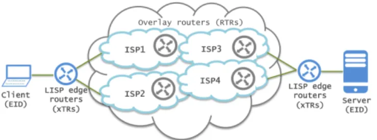
Fig. 1: A 2-subflow A-MPTCP scenario.
While representing a novel promising approach, the proposal in [4], [5] has three main limitations in many IP operations: (i) deterministically knowing the correct hashing function at LISP routers may be impossible; (ii) modifying the MPTCP endpoint kernel as proposed may be unpractical; (iii) the loose edge-to-edge LISP-enabled paths may not systematically lead to a throughput increase due to subflow delay differences.
In this paper, we overcome these drawbacks by proposing to exploit Traffic Engineering (TE) features we propose to add to the LISP architecture [8], [9], without the need to modify the MPTCP implementation at end-points. As depicted in Fig. 1, our proposal consists of building a LISP-TE network overlay that, combined with subflow state management and route selection functions, can transparently offer deterministic multipath forwarding to MPTCP connections, especially to large (elephant) flows. Transparently here means that MPTCP endpoints can keep working in their ‘greedy’ mode (opening as many subflows as set or needed) and that the overlay does not need any support from the underlay networks between LISP routers. Our proposal was implemented using open source nodes and the code is made available in github.com/lip6-lisp. In the following, Section II presents LISP and its TE extensions. In Section III, we describe different modes to guaranteeing deterministic forwarding of MPTCP subflows. In Section II, we specify the provisioning steps. In Section we report experimental results. Section VI concludes the paper.
II. LISP TRAFFICENGINEERING
When two LISP networks exchange traffic, a source end-point identifier (EID) in a site sends a packet to a destination EID in the other LISP site. Packets are encapsulated by an ingress tunnel router (ITR) toward the decapsulating egress tunnel router (ETR). The path from the ITR to the ETR is determined by the underlying routing protocol and metrics it uses to select a shortest path (typically BGP and interior gateway protocols). The ITR creates an IP-(UDP-LISP-)IP tunnel to ETR so that all the packets between the EIDs are encapsulated and sent via the tunnel. The LISP Mapping Sys-tem [11] defines a control-plane based on two main interfaces:
• Map-Resolver (MR): acceptsMAP-REQUESTs from ITRs and allows resolving the EID-to-RLOC mapping using a distributed mapping database;
• Map-Server (MS): learns authoritative EID-to-RLOC mappings from ETR via Map-Register messages and publishes them in the mapping database.
The LISP Delegated Database Tree (LISP-DDT) is a hier-archical, distributed database protocol, which embodies the delegation of authority to provide mappings from LISP EIDs to RLOCs, forwardingMAP-REQUESTacross Map-Resolvers and Map-Servers. The xTR (i.e., ITR/ETR) functionality is present in source and destination LISP routers [7]. For packets from source to destination, source xTR acts as ITR and destination xTR acts as ETR; for reverse traffic their role is reversed, i.e., destination xTR acts as ITR and source xTR acts as ETR.
In LISP Traffic Engineering (LISP-TE) extensions to the basic LISP mode are specified to allow using a loose path between ITR and ETR by introducing intermediate re-encapsulating tunneling routers (RTRs) [8]. There are several reasons why these features can be interesting. For instance:
• There may not be sufficient capacity or degraded
perfor-mance provided by the networks over a given subpath.
• There may be a policy set to avoid a particular subpath.
• There may be specific network functions (e.g., monitor-ing, traffic inspection nodes) or even a chain of network functions performed along one or many subpaths. The ability to pilot RTRs allows us to explicitly manage subpaths between RTRs. This makes the ITR-ETR direct path, from a basic LISP perspective, a composition of subpaths between ITR, RTRs, and ETR. This somehow is a form of Internet-scale segment routing; indeed there is recently also interest to use LISP-TE for segment routing [10]: segment routing combines source routing and tunneling to steer traffic through the transit network. In LISP-TE, the ETR can register multiple Explicit Locator Paths (ELPs) each identifying a path as a chain of RLOCs from source to destination. An RTR is a router that acts as both an ETR, by decapsulating packets where the destination address in the ‘outer’ IP header is one of its own RLOCs, and an ITR, by making a decision where to encapsulate the packet based on the next locator in the ELP towards the ETR. In addition to the set of EID prefixes to register, theMAP-REGISTERmessage includes one or more RLOCs to be used by the MS when forwarding
MAP-REQUESTs received through the mapping system. An ETR may request that the MS answersMAP-REQUESTs on its behalf by setting the “proxy MAP-REPLY” flag (P-bit) in the MAP-REGISTER message. In a LISP-TE context, building a LISP-TE overlay for A-MPTCP communications between two endpoints, say a source endpoint and a destination endpoint, shall be done in such a way that:
1) The destination xTRs register a set of ELPs on a per-EID-prefix basis (e.g., based on local information on the path states and traffic statistics);
2) The mapping system replies toMAP-REQUESTs coming from clients with one or many ELPs to use as loose forwarding inter-domain paths;
3) Different subflows from the source to the destination are forwarded over different ELPs, at least on the most unloaded direction, so that intermediate RTRs determin-istically guarantee no bottleneck.
A-MPTCP in a single direction can be sufficient. Otherwise, its implementation in both directions shall be decorrelated from each other, especially because Internet routing is often not symmetric. Different modes are conceivable to implement the above three steps. To ensure a deterministic binding of sub-flows to ELP, and hence ensure high performance, states have to be maintained at the LISP network nodes. Implementing the subflow forwarding can imply only control-plane operations, and also data-plane operations. The control on the overlay usage can be left to the destination, to the source, or inter-domain controllers, as elaborated in the next sections.
III. EXPLICITLOCATORPATHBINDINGMODES
We propose two possible ELP binding modes for MPTCP communications, describing protocol-level features needed. The specific signaling is later detailed in Section IV.
When the source EID sends a packet to the destination EID, source ITR sends a MAP-REQUESTmessage to the map resolver to get the ETR RLOC. When there are multiple ELPs defined leading to the destination ETR, that ETR may be reachable by different paths. The MAP-REPLY is sent by the destination ETR supposing MAP-REPLY proxying is not enabled. The mapping of ELP to subflows can be decided either at the destination ETR before replying with a single ELP or at the source ITR. Such a decision needs to be taken for each new subflow upon the detection of the MPTCP connection at the source xTR. Hence we have two modes of ELP-to-subflow binding operation described hereafter.
A. Destination-based stateful ELP binding
In this mode of operation, the destination ETR, upon receiving the MAP-REQUEST triggered by the detection of a new MPTCP subflow at the source ITR, sends one single ELP to the source so that the source associates that ELP with the subflow. When the source sends another requests upon the detection of an additional subflow, it sends a different ELP from the list of ELPs it has. In order to allow the ETR differentiate among different subflows, the source ITR first and the RTRs then must send the flow information in the MAP
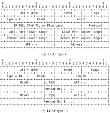
-REQUEST. This is possible by sendingMAP-REQUESTwith the LISP Canonical Address Format (LCAF) [9] message type 4 (see Fig. 2a) transporting four fields: source EID, destination EID, source TCP port and destination TCP port. The fifth field of the 5-tuple is protocol identifier and in this case it is TCP. In the reference single-homed endpoint situation, a TCP subflow is then identified based on source port because the other fields are equal for all subflows.
This mode is therefore stateful in the sense that the LISP network nodes serving the destination (ITRs, RTRs and the ETRs) need to maintain a subflow-to-ELP association table. Therefore, the best ELP selection algorithm runs on the destination ETR for each subsequent subflow-related MAP
-REQUEST. When intermediate RTRs (situated between source ITR and destination ETR) send the request, the ETR must first do a local lookup and see if the subflow is already associated with an ELP. Since the binding should be triggered by the
(a) LCAF type 4
(b) LCAF type 10
Fig. 2: Two LISP Canonical Address Format (LCAF) control-plane header types.
source ITR, requests from RTR should be dropped if the sub-flow indicated in the map request from that RTR is not already associated to any ELP. The benefits in keeping the state of all sub-flows of all incoming connection at the destination ETR and RTR level derive from a better system control by the destination network. The main drawback is scalability, as an important processing load is on the stateful nodes, in particular the RTRs that could be used by multiple destination networks.
B. Source-based stateless ELP binding
An alternative is to let the LISP nodes serving the desti-nation network stay stateless. This is possible by letting the destination ETR send the complete list of all ELPs along with their priorities to the source ITR and intermediate RTRs. Source ITR and RTRs can therefore send a standard non-LCAF MAP-REQUEST upon detection of a new subflow. The response is encapsulated using LCAF type 10 (see Fig. 2b) containing all the ELPs. The source ITR then selects the best path from the set of ELPs and associates each subflow with different ELP; the best ELP selection algorithm is later described. In this mode, the destination ETR and the RTRs do not need to keep any state about sub-flows associations to ELPs. This makes it a more scalable solution in [5]). However, the destination network does not have any control over sub-flow forwarding. There is still a missing brick: intermediate RTRs still need to identify the ELP associated to a given subflow. In absence of alternative techniques to uniquely identify the best ELP, we propose two light-way alternative methods:
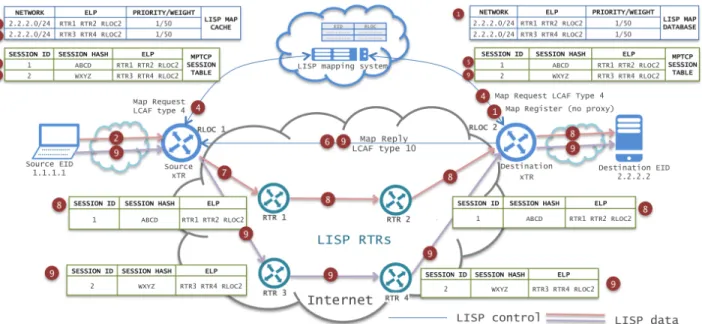
Fig. 3: A-MPTCP stateful provisioning steps.
1) Path Identifier (PID): the source ITR uses a field in the LISP data plane shim header (the flag field or the instance-ID field) to code an ELP identifier correspond-ing to the bindcorrespond-ing, that is a consecutive number of the ELP in the LCAF-10MAP-REPLY. In a convergent state, this order is later maintained also in the replies to RTRs. The mechanism would be altered if the set of registered ELPs changes during the transmission, which can be considered a rare event during a single connection. 2) ELP Link-Disjointness (ELD): in case ELPs do not
share any RTR-to-RTR link, then identifying the path in the data-plane is not necessary. Upon receiving the LCAF-10MAP-REPLY, the RTR can recognize the ELP based on the previous RTR address included in the outer header source address field. This implicit ELP recognition avoids therefore extra-work at the source ITR, yet it requires the destination to register link-disjoint ELP, which could be a best practice as it is a win-win option, if the RTR topology is sufficiently rich.
IV. A-MPTCP OVERLAYPROVISIONINGSTEPS
We specify in the following the AMPTCP overlay provi-sioning steps for the two binding modes.
A. Destination-based stateful ELP binding
Fig. 3 depicts an example configuration to describe the provisioning steps for the stateful case. They are as follows:
1) The destination xTR registers ELPs using MAP
-REGISTER messages with no MAP-REPLYproxying. 2) The source endpoint opens a MPTCP session with the
destination endpoint.
3) The source xTR catches the MPTCP-CAPABLE option and identifies the first MPTCP subflow in a local table with the hash of the 4-tuple source-destination EID IPs
and TCP ports (the ELP column is empty at this stage), plus a local MPTCP subflow session identifier.
4) The source xTR sends aMAP-REQUESTwith LCAF type 4 (Fig. 2a), transporting the 4-tuple source-dest TCP ports and EID IPs, which reaches the destination xTR. 5) The destination xTR selects the best ELP from its set
based on the local TE policy (the candidate ELP set should be precomputed for the sake of scalability) and binds it with the subflow. It stores in a local subflow table the subflow’s 4-tuple, a local MPTCP session ID (created for the first subflow), and the ELP bound to it. 6) The destination xTR replies to the received encapsulated
MAP-REQUESTusing aMAP-REPLYwith LCAF type 10 (Fig. 2b) containing the selected ELP.
7) The source xTR processes the MAP-REPLY, adds the content to the local mapping cache, binds the ELP to the subflow in the local table, and encapsulates accordingly. 8) Afterwards, upon reception of the first encapsulated packet(s), intermediate RTRs first send aMAP-REQUEST
to the destination ETR as in step 4, which replies with a LCAF type 10 MAP-REPLY as in step 6, acting then as in step 7. Depending on single-layer or multi-layer path signaling mode, they may either encapsulate the packet and send it to the ELP next hop or send another map request for the next hop, get the intra-domain ELP for next hop and then send the packet to the first entry in the ELP.
9) The source xTRs catches each additional subflow for each MPTCP flow, based on variation of source port only and MPTCP SYN+MP-JOINoptions, update the subflow table and send for each new subflow a MAP-REQUEST
as in point 4 - 8.
10) When source and destination xTRs catch the termination of a subflow (based on MPTCP option FIN) or a subflow is timeout, they clean the entry from the subflow table.
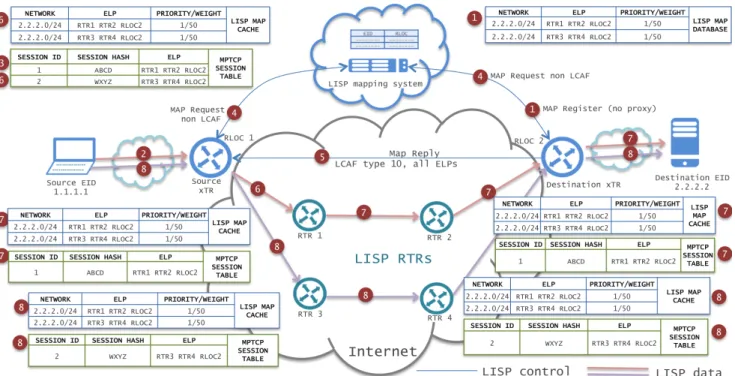
Fig. 4: A-MPTCP stateless provisioning steps.
B. Source-based stateless ELP binding
Fig. 4 depicts an example configuration to describe the provisioning steps for the stateless case. They are as follows: 1) The destination xTR registers ELPs using MAP
-REGISTER messages with LCAF type 10. Destination xTR can set the proxy bit indifferently either MAP
-REPLYproxy or no proxy.
2) The source endpoint opens a MPTCP session with the destination endpoint.
3) The source xTR catches the MPTCP-CAPABLE op-tion and identifies the MPTCP session in a local table with a hash of the 4-tuple source-destination TCP ports and EID IPs, plus a local identifier.
4) The source xTR sends a standard non-LCAF MAP
-REQUEST through the mapping system.
5) The destination xTR (if no proxy reply option) or the Map-Server/Map-Resolver (if proxy reply option) replies to the received encapsulated MAP-REQUEST
us-ing a MAP-REPLY with LCAF type 10 containing all the ELPs (Fig. 4 shows aMAP-REPLYfrom destination xTR, for the case when destination xTR registers with noMAP-REPLYproxy).
6) The source xTR processes the MAP-REPLY, adds all ELPs to the local mapping cache, finds the best ELP based on the local TE policy, binds an ELP to the subflow, and encapsulates accordingly to the ELP to the next RTR hop (the path identifier, PID, may be included in the LISP data header as specified in Section III.II). 7) Afterwards, upon reception of the first encapsulated
packet(s), intermediate RTRs first send aMAP-REQUEST
as in step 4, and receive a LCAF type 10MAP-REPLYas in step 5, acting then as in step 6. As in the stateful case,
they may or not work under multi-layer path signaling mode. To identify the next-hop RTRs can either use the PID in the LISP data header, or identify itself in the ELP under the ELD assumption, as explained in Section III.II. 8) The source xTR catches each additional MPTCP sub-flow, based on variation of source port only and MPTCP SYN+MP-JOIN options, updates the subflow table and binds the second (best) ELP to it.
9) As in the step 10 of the stateful mode, when source and destination xTRs catch the termination of a subflow (based on MPTCP option FIN) or a subflow is timeout, they clean the subflow entry from the subflow table. It is worth mentioning that the local TE path selection policies mentioned in step 6 above and in step 5 of the stateful provisioning step need to be carefully drafted so as to grant marginal improvement to ELP-to-subflow binding with respect to the standard/previous situation. As one of the main factors affecting transport protocol performance is the Round Trip Time (RTT), there is the need to collect RTT information in the overlay network topology composed of xTRs and RTRs. This can be natively done in a LISP network by enabling the so-called ‘RLOC probing’ functionality [7] that by piggybacking
MAP-REQUEST messages is able to collect RTT information. Once collected, this information can be used for the TE path selection policy run over the weighted overlay network graph.
V. EXPERIMENTAL RESULTS
The proposed framework was implemented and tested through large-scale experiments, as described in the following. We preferred running tests using real routing and end-point nodes rather than simulators because the complexity of the MPTCP+LISP-TE combined network system is such that
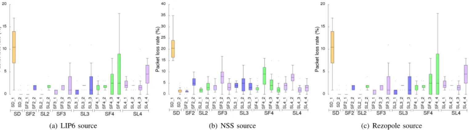
(a) LIP6 source (b) NSS source (c) Rezopole source
Fig. 5: Packet loss rate for different number of ELPs, in stateless and statefull modes (boxplot format).
(a) LIP6 source (b) NSS source (c) Rezopole source
Fig. 6: Correlation scatter of throughput vs differential RTT.
(a) LIP6 source (b) NSS source (c) Rezopole source
Fig. 7: Average RTT cumulative distribution functions for the different ELPs and sources.
using discrete-time event simulators would risk to introduce too much determinism with the risk of low credibility.
A. Implementation details
For running experimental tests, we extended the OpenLISP control-plane [25] and data-plane implementations adding: (i) LCAF 4 and LCAF 10 processing at the control-plane level; (ii) stateful and stateless functions, with the corresponding subflow table management functions; (iii) an enhanced RLOC probing behavior for collecting RTT measurements between overlay network nodes.
We centralized the collection of RLOC probing results at both ETR and ITR level to support the ELP search on the over-lay network graph weighted with RTT probing information. Then, we used as k-shortest path algorithm the one described in [26], to select ELPs with least differential RTT, with the goal to minimize the occurrence of head-of-line blocking when buffering packets.
The resulting versions v0.3 and v4.0 of the OpenLISP data-plane and control-plane software nodes including these extensions are released with a BSD license (see github.com/ lip6-lisp). We used the MPTCP linux implementation (v.0.90), with the default least-RTT scheduler.
B. Network testbed
We built an overlay network of RTRs over the LISP-Lab project testbed (lisplab.lip6.fr), interconnected to the global LISP network with the OpenLISP DDT root named ‘lambda’ (see ddt-root.org). For the tests, we set as destination the LISP-Lab site of Univ. of Missouri-Kansas City (UMKC), Kansas-City, USA, and used three different source LISP-Lab sites: the LIP6, Paris, France, Rezopole, in Lyon, France, and NSS, in east Paris, France, ones. Each source site deploys one xTR, one RTR and own EID prefix. To complete the overlay network, we use the following additional sites: Inria, in Sophia Antipolis, France, VNU, in Hanoi, Vietnam, POLIMI, in Milan, Italy,
each running an RTR. All the nodes, xTRs, RTRs and EIDs run as virtual machines with a number of cores varying from 1 to 4, from 2 to 2.6 Ghz, and live memory from 1 to 4 GB. EIDs implemented the version 0.90 of the open source MPTCP Linux kernel implementation (multipath-tcp.org).
We run 30 transfers for each mode (stateless and stateful), lasting 120 seconds each, using the iperf tool, for each source-destination pair, distributed on a period of two days. For each transfer, we first setup the nodes in the topology, and then use the RLOC probing between all nodes to collect RTTs between each pair of the node (used to calculate the ELP set for both source and destination xTRs). After deploying the computed ELP set to source and destination xTR, we start the transfer. As the overlay topology RTT were quite stable during the experiments, we got a fixed set of ELPs as follows:
• the UMKC communications, ELP1 was via
LIP6-UMKC, ELP2 via Rezopole-LIP6-UMKC, ELP3 via NSS-UMKC, and ELP4 via VNU-UMKC;
• for UMKC communications, ELP1 was via NSS-UMKC, ELP2 via Rezopole-NSS-UMKC, ELP3 via LIP6-UMKC, and ELP4 via VNU-UMKC;
• for Rezopole-UMKC communications, ELP1 was via Rezopole-UMKC, ELP2 via LIP6-UMKC, ELP3 via NSS-UMKC, and ELP4 via VNU-UMKC.
In the following, SLX and SFX indicates the stateless and stateful tests, respectively, run with a number of X ELPs. SD stands for standard transmission, that is using basic LISP-MPTCP communications with LISP-TE stitching as in [4], [5] with two subflows. SDY, SLXY and SFXY indicates the Yth
subflow used in SD, SL and SF modes, respectively.
C. Tests characterization
Let us characterize first the tests, in order to better under-stand the throughput results.
Fig. 5 gives the experienced packet loss, at the subflow level, for the various modes with a number of subflows ranging from 2 to 4. The SD mode suffered an important packet loss during the experiments. Among the sources, the NSS one suffered more, essentially because we suspect the employed datacenter run shaping policies at the top-of-rack level.
Fig. 6 gives three scatter plots, one for each source, corre-lating the throughput to the differential RTT (the minimum RTT difference among subflows) for all the tests. We can observe the strong positive correlation between the two factors, with highest throughput reached for least differential RTTs.
Fig. 7 completes the picture with the distribution of the RTT (average among the RTTs of the single subflows) for the different ELPs. The fourth ELP for all sources suffers from a much higher RTT, hence one can expect its addition can generate head-of-line blocking. For the NSS source, ELP3 has a slightly higher RTT than the others. The remaining ELPs have a differential RTT quite low.
D. Throughput results
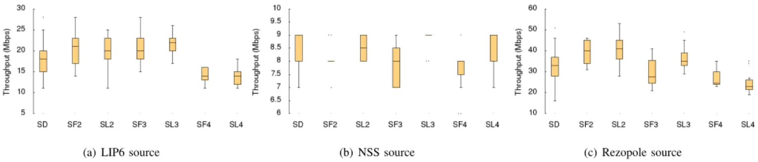
Fig. 8 reports the achieved performance in terms of throughput for the different source-destination pairs, under
the stateful and stateless modes, with the number of ELPs ranging from 1 to 4. We can notice that there is practically no improvement with the NSS source: this is likely the result of the many retransmissions due to the observed higher packet loss rates, likely due to shaping in the source network. For the other two sources, the gain ranges from 10% to 25% with two paths, hence without adding paths with respect to SD, just bypassing the default routes by using the network overlay. Adding a third ELP leads marginal gains only for the LIP6 source. Adding the fourth ELP, with high RTT, does decrease the throughput as expected, likely because of head-of-line blocking. Finally, an important observation is that there is no better mode in terms of throughput performance between stateless and statefull modes.
With a deeper look to the subflow contribution to the throughput, shown in Fig. 9, also in perspective with the ELP RTTs qualified in Fig. 7, we can observe that the fourth ELP does indeed bring a very low, in practice null contribution, besides causing likely buffering issues. Then, we can see the impact of the scheduler, which load mostly one subflow (the least RTT one), this subflow often being the first one (because we can see there can be a very low difference between the RTTs of ELP1 and ELP2 for all sources). We identify in the scheduler an important potential of further bandwidth aggregation, as other ELPs with very close RTT to the least RTT one could be used more with another type of scheduler. Unfortunately, such an advanced scheduler is still not designed and implemented as of our knowledge.
VI. CONCLUSION
We described in this paper a novel overlay network pro-tocol architecture based on MPTCP and LISP-TE propro-tocols, with some extensions in particular to the overlay routers state management. Despite we could benefit from only few overlay network nodes, we could experimentally evaluate our proposals showing the positive impact by using our overlay network, the negative impact of long RTTs on some MPTCP subflows, and the strong correlation between the differential RTT among subflows and the throughput performance.
Different directions of further investigations are open. First, we believe our approach, making use of an incrementally deployable protocol such as LISP, can be a viable one for building an overlay network across network domains such as via internet exchange points or software-defined network do-mains. Second, the major limitation to the achievable through-put gain being represented by the MPTCP scheduler, we plan to design a new scheduler able to better aggregate bandwidth on multiple subflows with different RTT performance. As introducing an advanced scheduler may be too difficult to do at the device level, and as devices may not even be MPTCP capable, one promising direction is to integrate it into MPTCP proxies using frameworks such as the one described in [27].
ACKNOWLEDGEMENT
This work was funded by the ANR LISP-Lab project (lisplab.lip6.fr - Grant No: ANR-13-INFR-0009), the FUI 15
(a) LIP6 source (b) NSS source (c) Rezopole source
Fig. 8: Throughput performance for different number of ELPs, in stateless and statefull modes (boxplot format).
(a) LIP6 source (b) NSS source (c) Rezopole source
Fig. 9: ELPs contribution to the MPTCP connection throughput.
project RAVIR (http://www.ravir.io) and the EIT ICT-Labs Future Networking Services action line (eitictlabs.eu).
We thank G. Maier, D. Medhi, and D. Saucez for making available their LISP-Lab site, and P. Bellavista for his valuable feedback. We also thank N. Kukreja for his artworks and support in the tests for his master thesis, and R. Alvizu for the discussions on least differential delay path selection.
REFERENCES
[1] E. Elena, J.-L. Rougier, S. Secci, “Characterisation of AS-level Path Deviations and Multipath in Internet Routing”, in Proc. of NGI 2010. [2] “Configuring BGP to Select Multiple BGP Paths”, JUNOS document. [3] A. Lange, “Issues in Revising BGP-4”, draft-ietf-idr-bgp-issues-06, 2012. [4] M. Coudron, S. Secci, G. Pujolle, “Augmented Multipath TCP
Commu-nications”, in Proc. of IEEE ICNP 2013.
[5] M. Coudron, S. Secci, G. Pujolle, P. Raad, P. Gallard, “Cross-layer Cooperation to Boost Multipath TCP Performance in Cloud Networks”, in Proc. of IEEE CLOUDNET 2013.
[6] C. Raiciu et al., “Improving Datacenter Performance and Robustness with Multipath TCP”, in Proc. of ACM SIGCOMM 2011.
[7] D. Lewis et al., “Locator/ID Separation Protocol (LISP)”, RFC 6830, Jan. 2013.
[8] D. Farinacci, P. Lahiri, M. Kowal, “LISP Traffic Engineering Use-Cases”, draft-farinacci-lisp-te-07, Sept. 2014.
[9] D. Farinacci, D. Meyer, J. Snijders, “LISP Canonical Address Format (LCAF) ”, draft-ietf-lisp-lcaf-05, May 2014.
[10] F. Brockners et al., “LISP Extensions for Segment Routing”, draft-brockners-lisp-sr-01, Feb. 2014.
[11] V. Fuller, D. Farinacci, “Locator/ID Separation Protocol (LISP) Map-Server Interface”, RFC 6833, Jan. 2013.
[12] N. McKeown, A. Mekkittikul, V. Anantharam, J. Walrand, “Achieving 100% throughput in an input-queued switch”, IEEE Transactions on Communications, Vol. 47, No. 8, pp:1260-1267, 1999.
[13] S. Rai, O. Deshpande, C. Ou, U. Martel, B. Mukherjee, “Reliable multipath provisioning for high-capacity backbone mesh networks”, IEEE/ACM Trans. on Networking, Vol. 15, pp. 803-812, 2007.
[14] S.-J. Lee, M. Gerla, “Split multipath routing with maximally disjoint paths in ad hoc networks”, in Proc. of ICC 2001.
[15] J. Tang, G. Xue, “Node-disjoint path routing in wireless networks: tradeoff between path lifetime and total energy”, in Proc. of ICC 2004. [16] J. Chen, S.-H. Chan, V. O. Li, “Multipath routing for video delivery
over bandwidth-limited networks”, IEEE J. on Selected Areas in Com-munications, Vol. 22, pp. 1920-1932, 2004.
[17] F. Paganini, E. Mallada, “A Unified Approach to Congestion Control and Node-Based Multipath Routing”, IEEE/ACM Trans. on Networking, Vol. 17, pp. 1413-1426, 2009.
[18] S. S. Ahuja, T. Korkmaz, M. Krunz, “Minimizing the differential delay for virtually concatenated Ethernet over SONET systems”, in Proc. of ICCCN 2004.
[19] A. Srivastava, S. Acharya, M. Alicherry, B. Gupta, P. Risbood, “Differ-ential delay aware routing for Ethernet over SONET/SDH”, in Proc. of IEEE INFOCOM 2005.
[20] A. Srivastava, “Flow aware differential delay routing for next-generation Ethernet over SONET/SDH”, in Proc. of IEEE ICC 2006.
[21] W. Zhang, J. Tang, C. Wang, S. De Soysa, “Reliable adaptive multipath provisioning with bandwidth and differential delay constraints”, in Proc. of IEEE INFOCOM 2010.
[22] H. Sheng, C. U. Martel, B. Mukherjee, “Survivable Multipath Provi-sioning With Differential Delay Constraint in Telecom Mesh Networks”, IEEE/ACM Trans. on Networking, Vol. 19, pp. 657-669, 2011. [23] R. Bhandari, Survivable networks: algorithms for diverse routing,
Springer, 1999.
[24] D. Andersen, H. Balakrishnan, F. Kaashoek, and R. Morris “Resilient Overlay Networks”, ACM SIGCOMM Computer Communication Review, Vol. 32 pp. 1-66,2002
[25] D.C. Phung, S. Secci, D. Saucez, L. Iannone, “The OpenLISP Control-Plane Architecture”, IEEE Network Magazine, Vol. 28, No. 2, pp: 24-40, March-April 2014.
[26] R. Alvizu, G. Maier, M. Tornatore, M. Piro, “Differential delay constrained multipath routing for SDN and optical networks”, Electronic Notes in Discrete Mathematics, Vol. 52, pp: 277-284, 2016.
[27] M. Boucadair et al., “Extensions for Network-Assisted MPTCP De-ployment Models”, draft-boucadair-mptcp-plain-mode-10, IETF technical report, March 2017.