Nli ACHUSETTS INSTITUTE OF TECHNOLOGY
JUL 3 1 2002
LIBRARIES
Design and Development of a High-Performance,
Low-Cost Robotics Platform for Research and
BARKERSubmitted to the Department of Electrical Engineering and
Computer
Science
in partial fulfillment of the requirements for the degree of Master of Engineering in Computer Science and Engineering
at the
MASSACHUSETTS INSTITUTE OF TECHNOLOGY
May 2001 La n
@Max
Bajracharya, MMI. All rights reserved.The author hereby grants to MIT permission to reproduce and distribute publicly paper and electronic copies of this thesis document
in whole or in part.
Author ...
Department of Electrical Engineering and Computer Science May 10, 2001
Certified by..
...
V
Lynn Andrea SteinAssociate Professor of Computer Science Tesis S.,upervisor
Accepted by ...
--
ti - . ..- -. . .- -*' ". .Arthur C. Smith Chairman, Department Committee on Graduate Students
Education
by
MITLibraries
Document Services Room 14-0551 77 Massachusetts Avenue Cambridge, MA 02139 Ph: 617.253.2800 Email: docs@mit.edu http://Iibraries.mit.edu/docsDISCLAIMER OF QUALITY
Due to the condition of the original material, there are unavoidable
flaws in this reproduction. We have made every effort possible to provide you with the best copy available. If you are dissatisfied with
this product and find it unusable, please contact Document Services as soon as possible.
Thank you.
The images contained in this document are of
the best quality available.
Design and Development of a High-Performance, Low-Cost
Robotics Platform for Research and Education
by
Max Bajracharya
Submitted to the Department of Electrical Engineering and Computer Science on May 10, 2001, in partial fulfillment of the
requirements for the degree of
Master of Engineering in Computer Science and Engineering
Abstract
We have developed a high-performance, low-cost autonomous robot controller plat-form targeted towards students and researchers. The platplat-form exhibits more capabil-ities than existing platforms for a similar cost while remaining accessible to a diverse group of users. To motivate the design of intelligent robot navigation and localization, we have also built an environment to simulate real world conditions while simplifying mechanical constraints, and an example robot that can interact with the environment. In addition, we ran a month-long course to test the platform. The design decisions and tradeoffs in the platform, environment, and robots, as well as their motivation, capabilities, and potential applications are included in this paper.
Thesis Supervisor: Lynn Andrea Stein
Title: Associate Professor of Computer Science
Acknowledgments
The design of the platform, environment, and robot was done jointly with Edwin Olson; I would like to acknowledge his contributions to the project. While the project was done jointly, the thesis documents were written independently and reflect different
perspectives on the work. I recommend Olson's thesis [12] in addition to this one. We would like to acknowledge the sponsors of our autonomous robotics contest who helped by donating parts and money to make it possible: Hitachi Semiconductor, PADS/Innoveda, Maxim, MIT EE/CS department, Acroname, ISSI, and National Semiconductor.
We would also like to thank the students who took part in the month-long contest for their help in testing and suggesting modifications to the platform.
Dissemination of this work has been supported by National Science Foundation
CISE Educational Innovation Grant No. 99-79859 to Professor Lynn Andrea Stein.
Any opinions, findings, conclusions or recommendations expressed in this material are those of the author(s) and do not necessarily reflect the views of the National Science Foundation.
Contents
1 Introduction 9 1.1 Motivation . . . . 9 1.2 Purpose ... .. .. ... 10 1.3 Organization . . . . 11 2 Controller Platform 12 2.1 Requirements . . . . 12 2.2 Existing Platforms . . . . 13 2.3 Controller Board . . . . 16 2.3.1 Microcontroller . . . . 16 2.3.2 Peripherals . . . . 17 2.3.3 Communication . . . . 20 2.3.4 LC D . . . . 20 2.3.5 Power . . . . 21 2.3.6 C ost . . . . 22 2.4 Development Environment . . . . ... . . . . 22 2.4.1 Development Tools . . . . 22 2.4.2 Runtime Environment . . . . 23 3 The Environment 25 3.1 Requirements . . . . 25 3.2 Physical Constraints . . . . 263 .4 G o a ls . . . . 4 The 4.1 4.2 4.3 4.4 4.5 4.6 Robots Requirements . . . Locomotion . . . . Chassis . . . . Batteries . . . . Sensors . . . . High Level Control 4.6.1 Behavior . . 4.6.2 Localization 4.6.3 Navigation . 5 Results 5.1 Coursework . . . . 5.2 Future Work . . . . 5.2.1 Platform Fixes . . . . 5.2.2 Platform Enhancements . . . 5.2.3 Environment Generalizations 5.2.4 Robot Enhancements . . . . . 6 Conclusion A Platform Specifications B Schematics/Layout
B.1 Annotated Platform Schematics . . . B.1.1 Power . . . . B.1.2 Controller . . . . B.1.3 Serial I/O . . . . B.1.4 DRAM . . . . B.1.5 Analog Input . . . . 27 29 29 29 33 33 35 35 35 37 38 41 41 42 42 42 43 43 44 46 47 . . . . . 47 . . . . . 47 . . . . . 47 . . . . . 48 . . . . . 48 . . . . . 48
B.1.6 Digital I/O . . . . 49
B.1.7 Motor Drivers . . . . 49
B.2 Annotated Platform Layout . . . . 57
B.3 IR Beacon Schematics . . . . 57
B.4 IR Beacon Layout . . . . 57
C Programming Process 63 C.1 Development Environment . . . . 63
C.1.1 Compiling a Program . . . . 63
C.1.2 Programming the Board and Running gdb . . . . 63
List of Figures
2-1 The Handy Board (4.25 x 3.15 in.) . . . .
2-2 The LEGO Mindstorms RCX (2.5 x 3.5 in.) . . . . 2-3 The BASIC Stamp2 (14 Pin DIP package) . . . . .
2-4 The Compaq RoboSkiff (approx. 5.0 x 4.0 in.) . . .
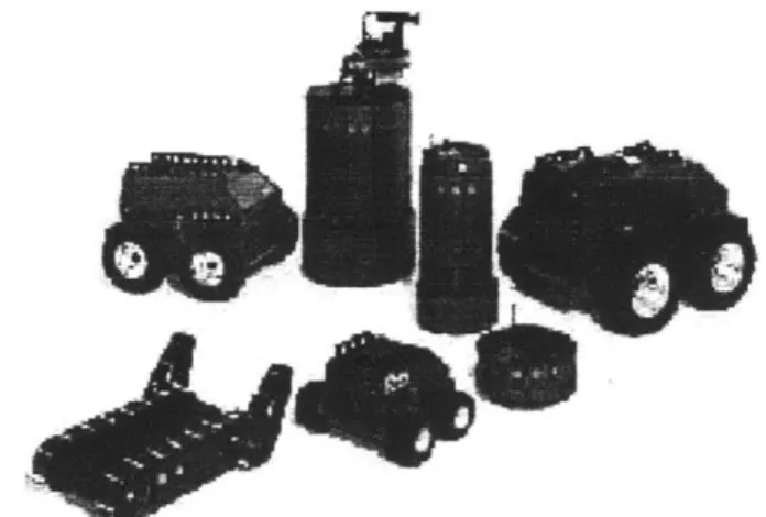
2-5 The iRobot RWI Family of Robots . . . .
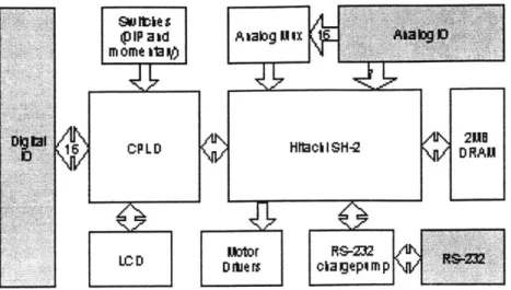
2-6 Controller board block diagram . . . .
2-7 Controller board photograph . . . . 3-1 Photograph of a possible environment configuration 3-2 Photograph of a beacon transmitter/receiver board
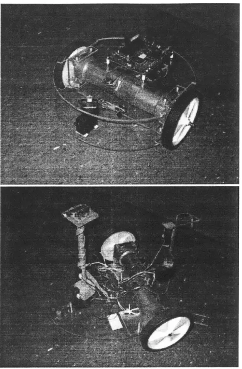
4-1 Photograph of example robots . . . . 4-2 Position/time graph of control system . . . . 4-3 Discharge of NiMH battery pack (powering controller board) 4-4 Photograph of NiMH battery pack used . . . . 4-5 Graph of IR range sensor data . . . . 4-6 IR range sensor attached to position controlled servo motor .
4-7 A example map created by a robot: a grid of one inch resolution, with the robot taking a path around a target surrounded by a 4 ft. square of walls; the dark points represent the robot's path, while the lighter points are the obstacles it detects . . . .
B -1 P ow er . . . . B-2 C ontroller . . . . . . . . 14 . . . . 1 5 . . . . 15 . . . . 1 5 . . . . 1 6 . . . . 17 . . . . 18 . . . . 26 . . . . 27 31 32 34 34 36 37 40 50 51
B-3 Digital I/O ... 52
B-4 DRAM. ... ... . 53
B-5 Serial I/O . . . . 54
B-6 Analog I/O . . . . 55
B-7 Motor Drivers ... ... 56
B-8 Controller Board Layout (top) . . . . 58
B-9 Controller Board Layout (bottom) . . . . 59
B-10 IR Beacon Schematic . . . . 60
B-11 IR Beacon Layout (top) . . . . 61
B-12 IR Beacon Layout (bottom) . . . . 62
D-1 Alkaline discharge characteristics . . . . 66
D-2 NiCad discharge characteristics . . . . 67
D-3 Lithium-Ion discharge characteristics . . . . 67
D-4 NiMH discharge characteristics . . . . 68
Chapter 1
Introduction
1.1
Motivation
As technology is improving, both the capabilities and roles of autonomous mobile robots are expanding. Lower power but more powerful processors, better batteries, and better sensors are making intelligent autonomous robots feasible. Smaller, faster processors are making the simultaneous control of actuators, collection of sensor data, and execution of AI algorithms possible in real-time on an embedded system. New battery technology is providing lighter batteries with better discharge characteristics, allowing robots to run longer and power more sensors. And new sensor technology is allowing cheaper and better range and imaging sensors.
Consequently, robots have the potential to be practical for exploring and interact-ing with hazardous environments as well as beinteract-ing useful in the home and workplace. Robots are becoming popular for exploring planets, handling hazardous waste, fight-ing fires, discoverfight-ing mines, scoutfight-ing hostile territory, mowfight-ing lawns, and deliverfight-ing office mail. Additionally, artificial intelligence and autonomous robots are becom-ing more widely accepted in society. Robot competitions like MIT's Autonomous Lego Robotics Contest, 6.270, are expanding and catching on at many other univer-sities. As a result, research and education in robotics and artificial intelligence for autonomous systems is becoming more prevalent.
Unfortunately, few tools exist for either students or researchers to quickly and
cheaply prototype a mobile robot and test algorithms on it. For the most part, inex-pensive controller boards and kits like the Handy Board [11], Mindstorms Lego Kit [2], BASIC Stamp [6], and others lack the capabilities to intelligently control a robot consisting of many actuators and sensors, while more capable, pre-built robot plat-forms like iRobot/RWI's ATRV [8] and other such research robots are a substantial investment for students and researchers.
1.2
Purpose
The lack of an inexpensive controller board capable of controlling a sophisticated robot has resulted in an empty niche for robot platforms. Students and researchers who are interested in prototyping and controlling a sophisticated robot have few options (these options are reviewed in 2.2). Consequently, the goal of this thesis is to:
1. Develop a cost-effective, simple, yet powerful robotics platform for research and
education.
2. Design an environment to motivate development of intelligent autonomous robots.
3. Suggest example robots which can navigate and interact with the environment.
The platform, consisting of a controller board and its development and runtime environment, will be aimed at building a robot capable of navigating a mechanically simple yet conceptually difficult environment with sensors just short of vision or complex imaging devices. This is a reasonable approximation to a home or office-like environment, while still providing a strong conceptual similarity to an unknown planet or environment. The suggested robots focus mainly on localization using odometry supplemented with triangulation and mapping methods, and navigation based path finding to a target and obstacle avoidance.
1.3
Organization
This document begins by describing the requirements for a capable, yet low-cost robotics platform, and then delves into the details of the platform, discussing the controller board, development environment, and runtime environment. The environ-ment created to motivate the developenviron-ment of example robots and also used in a course using the platform is then discussed. And finally, some example robots built which can interact with the environment are explained. To support the material, a course taught using the platform is also discussed, along with future work.
Chapter 2
Controller Platform
2.1
Requirements
Our goal in designing a robot platform was to design a controller board and develop-ment and runtime environdevelop-ment which was simple and inexpensive while being capable and robust. The platform must be able to support relatively high current, high torque
DC motors, quadrature phase encoders, position controlled servo motors, and a large
number of analog and digital sensors. The kernel should provide multi-threading sup-port as well as an interface to the basic hardware peripherals. And the development toolchain should be accessible and easy to use.
In order to keep the board simple and inexpensive, the number of components should be relatively small. An undergraduate electrical engineer should be able to understand the board design, modify it as needed, and use it as a reference for a similar microcontroller board. The board should also be affordable to a student, constraining it to cost below several hundred dollars. However, the board should also provide enough capability for a graduate student or researcher to develop sophisticated control systems and navigation algorithms. It should also support a standard programming language and inexpensive development environment.
2.2
Existing Platforms
By far the most successful robot controller board which exists is the Handy Board [11].
Designed by Fred Martin and Randy Sargent at the MIT Media Lab, it has been used as the robot controller for 6.270, MIT's Autonomous Lego Robot Competition and has become a favorite among hobbyists. Unlike most other platforms, it is available from several robotics suppliers, is used by many other university courses, and is well documented, both by its designers and third-parties on the web. The board is based on a Motorola 68HC11 controller, but only runs at 1 MIPS and only has 32K of memory. With mainly through-hole and socketed parts and using Interactive C (an interpreted language), the Handy Board caters to a hobbyist's needs, but does not provide adequate processing power or memory for many real-time navigation and mapping algorithms.
Another simple, hobbyist board is the BASIC Stamp [6], which is based on a
PIC microcontroller. It is extremely simple and can be programmed in interpreted BASIC. However, at best, it can only run at 10,000 instructions per second and can
only hold up to 4,000 instructions. The Stamp also only provides digital I/O; it does not have any on-board peripherals like motor drivers or A/D converter.
The LEGO MINDSTORMS kit controller board, the RCX [2] is designed more for young children, but still provides a good set of peripherals and simple sensor interfaces. It is based on a Hitachi H8 microcontroller. However, because connectors are designed to interface directly to LEGO bricks and custom LEGO motors and sensors, it does not generalize beyond LEGO robots. It also does not provide the processing power or memory to develop sophisticated algorithms.
Khepra [1] is an small, inexpensive, modular robotics kit for education. It is based on a Motorola 68331 processor, but is designed mainly to be controlled by an external host. The robot itself only has 256K of RAM, which prevents it from doing much on-board processing (maintaining a map for instance). It also has a specific form factor, with motors and sensors. So, motors, sensors, and mechanical design cannot be chosen for different environments or conditions.
Figure 2-1: The Handy Board (4.25 x 3.15 in.)
The Palm Pilot Robot Kit [3] is another option available. It is a kit which can be interfaced to a Palm Pilot which acts as the controller. While the Palm pro-vides adequate processing power, it runs its own operating system, making real-time processing difficult. It is also limited to a serial connection to an external interface board, which is used to control motors and processor sensor input. The kit, without the Palm Pilot, also costs approximately the same as our platform.
On the more expensive end of the spectrum, the Compaq Personal Server with the additional Robot Controller Card [5] provides sufficient processing power and memory, but is probably prohibitively expensive and overly complex. The Compaq Personal Server uses a StrongArm SA110 CPU, running at 206 MHz, which has no on-board peripherals, and requires external modules, including the Robot Controller Card, which adds motor drivers and sensor I/O. The Server runs Linux and can be programmed in Java; but this adds a large amount of unnecessary overhead to a real-time embedded system and requires more complex drivers to be written. The main bus is PCI which further complicates the board.
Beyond controller boards, pre-built robots [8] with on-board computers can also be bought. While these platforms provide a simple solution to test algorithms, the robots are very specific and limited to the environment for which they are built. They are also generally beyond the budget of a student.
ZI : :i~r' 'R ..
Figure 2-2: The LEGO Mindstorms RCX (2.5 x 3.5 in.)
Figure 2-3: The BASIC Stamp2 (14 Pin DIP package)
~wi
Figure 2-5: The iRobot RWI Family of Robots
2.3
Controller Board
We designed our controller board to be a compromise between the expensive, complex platforms and the simpler, cheaper, more accessible ones. To this end, it is intended to provide solid CPU performance, a large memory capacity, and a rich set of peripherals with a simple interface.
2.3.1
Microcontroller
The defining component of the board is the microcontroller. It determines the capabil-ities of the platform as well as what peripherals need to and can be added externally. After looking at several microcontrollers, ranging from extremely simple, small con-trollers like Microchip's PICs (generally 16MHz) to higher-end processors with very few peripherals, like a StrongARM processor (200MHz), we eventually decided on the Hitachi SuperH (SH) series [4] as the best compromise. The SH controllers are more powerful than the Hitachi H8 series (8-bit, 8MHz) and the standard Motorola
68HC11 (8-bit, 2MHz) or Intel 8051 (8-bit, 12MHz), but still easier to work with and
have more on-board peripherals than a high-end processor. The controller we decided on was the SH-2, 7044. It has a high speed 32-bit RISC core (30 MIPS at 30MHz) and a rich set of on-board peripherals. It also has an on-board DRAM controller, making memory interface easier, and a 5V TTL bus with a simple SRAM-like
72-(DIP a d A aIbg Mix A _tg D
mome a0Y
Digital/5 PLD Htach I SH-2 /Vl\ 2HO
/ RAM
LC D Kor RS-232 /a\ DC
DlM r cla gepp \4V-23
Figure 2-6: Controller board block diagram
face, making interfacing to external components easy as well. The SH-2 has 256K of on-chip FLASH for storing programs data, and 4K of extremely fast SRAM, which can be used as a cache if external memory is used.
2.3.2
Peripherals
Memory
Because the Hitachi SH-2 processor provides an integrated DRAM controller, external DRAM can be added easily. The other option to add more memory to the controller board would be external SRAM, which, although much faster, increases the cost of the board substantially. We have added 2 MB of external DRAM to the controller, balancing the cost of memory with the flexibility in designing control algorithms. 2
MB of memory should be enough room to store a substantial program while still providing adequate space for a low resolution map of the environment. This amount
of memory may be inadequate for image processing, but this is justified by the fact that the board is not designed to directly support a vision sensor.
The external DRAM is simple to interface to largely because the SH-2 does not support an MMU (memory management unit), and consequently cannot support virtual memory. This is an advantage since it keeps the platform simple and reduces any overhead that might be introduced by virtual memory.
Sensor Interfaces
Most sensors (short of imaging sensors) used in robotics either provide a digital (on/off) signal, an analog signal, or a varying period or duty cycle pulse. These might include touch sensors, analog IR range finders, sonar sensors, or encoder in-puts. The SH-2 supports all of these sensors by providing digital I/O ports, an A/D,
and a multifunction timer unit.
Digital I/O
Although the SH-2 allows direct digital input and output, we have added a CPLD (complex programmable logic device) through which the digital I/O is mapped. Using the CPLD to provide memory mapped digital I/O greatly increases the number of ports that are possible as well as provides the ability to add useful logic to the controller board.
Analog Inputs
To digitize analog signals, the SH-2 provides a mid-speed 10-bit analog to digital converter with a built in 8-to-1 multiplexer. However, because we anticipated that more than eight analog inputs would be necessary, we have added an extra external 16-to-1 analog multiplexer which feeds one of the eight SH-2 analog inputs. The platform then supports seven fast analog inputs and sixteen slower ones. Inputs going directly to the SH-2 can be digitized in approximately 10 us, while those going through the external MUX require the additional 250 ns of switching time on the
MUX.
Timer Inputs
The SH-2 also conveniently provides a multifunction timer unit which supports input capture and compare modes. As a result, reading sensors which provide a variable pulse width signal, like many sonar sensors, is simple. The SH-2 also supports quadra-ture phase encoder decoding, which makes reading a directional encoder signal from
a motor easy as well.
Motor Interfaces
DC Motors
The SH-2's timer unit is also used to provide PWM (pulse width modulated) signals to a motor driver, which can then drive DC motors. A PWM signal, of constant period but variable duty cycle, can provide a signal of 16-bit resolution (0-100% duty
cycle). With an extra direction pin, the signal can be sent to a motor driver (full H-bridge) which can then allow an external, high current line to supply power to the motors. The controller board has two, two-channel motor drivers, which support 2 amps. of nominal current per channel. So a total of four high current motors can be driven by the board. Extra PWM channels are headered, however, so with additional external motor drivers, more DC motors can be used.
Servo Motors
The PWM signal generated by the SH-2 can also be used to control a position con-trolled servo motor. These self-contained motors, generally providing 180 degrees of rotation, are controlled by a variable length pulse, where the motor position is proportional to the pulse length.
2.3.3
Communication
To communicate with an external host, such as a PC, or other device, the SH-2 provides a UART (universal asynchronous receiver/transmitter) supporting two
RS-232 (serial) channels. However, since the signal level is TTL level and RS-RS-232 requires
+/-12V, an external charge pump was required, and so was added externally.
2.3.4
LCD
To provide debugging feedback or status information, we have added a 2 line, 16 character LCD (liquid crystal display). The LCD has an integrated controller which
provides a simple bus interface, rather than requiring the CPU to control the display. However, because the LCD bus interface, whose maximum operating frequency is 1 MHz, is substantially slower than the SH-2's 30 MHz bus speed, the control is buffered through the added CPLD. The SH-2 can enact fast bus transactions with the CPLD which can then buffer and re-time the LCD signals. This prevents the CPU from having to waste the cycles waiting to slow down the signals.
2.3.5
Power
In most cases, the controller board will be powered by a battery pack. However, this battery pack will also probably power the motors and actuators of the robot. Although an alternative to using a single power supply for both the controller and actuators is to use separate supplies, using a single supply simplifies the overall robot design and reduces the space required. But having a single supply means that it is subject to large current draws from the actuators and will tend to be of a higher voltage than required by the controller board.
Most DC motors which would be practical for a robot operate at a 12-24V range. However, the controller board operates at 5V. To provide both voltages, the power supply, generally a battery pack, provides 12-24V directly to the motors while the con-troller board regulates this voltage down to 5V. This allows the motors to draw large currents directly from the supply. However, to provide a constant, non-fluctuating supply to the control board, the board must do substantial filtering.
To provide regulated power to the controller, we considered both a linear regulator and switching regulator. Although a linear regulator tends to be simpler, because it regulates power by dissipating power through a variable resistor, regulating a high voltage down to a low one is very inefficient; all of the excess power is dissipated in heat. A better solution is a switching regulator, which tends to be more efficient, even with large differences between input and output. However, because a switching regulator does not generate as smooth an output as a linear regulator, more external components are required to filter it, and consequently leads to a more complicated design. The first revision of the design used a linear regulator, while the second
sion used a switcher to increase efficiency. However, because the switching regulator could not handle current transients well enough, the third revision will consist of two regulators. A switching regulator will regulate the supply to the main components on the board, while a linear supply will regulate the supply to the sensors and servo motors.
The board currently draws about 300 mA with all the on-board peripherals run-ning (A/D, timers, etc. as well as LCD).
2.3.6
Cost
The controller board costs approximately $300, including the components and fabri-cation and assembly. The main components on the board (MCU, memory, CPLD) are most of the cost of the components, and so the cost can be reduced by removing the optional Altera CPLD. The fabrication and assembly also adds substantially to the cost, but can be reduced by running large quantities of boards.
2.4
Development Environment
2.4.1
Development Tools
Since the Hitachi SH-2 microcontroller is already supported by the GNU C/C++ compiler (gcc) and the GNU development tools are free and generally well supported, we decided that they would be appropriate. The only other options for most micro-processors is to either write directly in assembly or to purchase a higher level language compiler from the manufacturer, which tends to be expensive. We had no difficulties in building the cross compilers, assemblers, and linkers to generate SH-2 assembly in x86 Linux machines.
The simplest way to program the controller once the machine code is generated is to reprogram the on-board FLASH memory. This involves a bootstrapping program distributed by Hitachi which interfaces to a simple boot-loader in the SH-2 ROM. However, because the controller's on-board FLASH is only rated for several hundreds
of reprogramming cycles, a user could easily consume those cycles with an iterative development process.
So, as an alternative to reprogramming the FLASH on every development
it-eration, a gdb (GNU debugger) stub can be loaded into FLASH which can then interactively load code to DRAM and run it. The gdb stub only needs to be loaded once, and allows a user to interactively debug code remotely from a host PC (x86 Linux machine in our case) via a serial connection. Although the user code needs to be loaded into DRAM every time the board is reset, it prevents the need to repro-gram the on-board FLASH constantly. Of course, when a final prorepro-gram is developed, this can be programmed into FLASH, replacing the gdb stub, and will run on the controller boot-up.
2.4.2 Runtime Environment
Standard library functions, like malloc and printf, are available to users by statically linking to either GNU libc (http://www.gnu.org/software/libc/) or Cygnus newlib (http://sources.redhat.com/newlib/) libraries. While both packages provide similar capabilities, the Cygnus newlib library is targeted to smaller, embedded systems. As
a result, we used the Cygnus package for our development.
Kernel
However, neither library package provides threading utilities, which are necessary to implement a robot capable of simultaneously reading sensors, controlling actuators, and implementing navigation algorithms. Threads allow a user to modularize the control of input, output, and algorithms used at a higher level. Although using a previously developed real-time kernel was a possibility, we did not want the extra complexity and learning time involved with these kernels. As a result, we have added our own simple kernel which supports multi-threading. It uses the standard posix threads interface and was written largely by Edwin Olson [12]. The implementation uses a multilevel priority scheme to schedule tasks.
Multithreading in programs is handled by a simple scheduler, which simply main-tains a list of tasks and an associated priority. Each task is given a certain time period to execute before the context is switched. Tasks can also sleep for some time period or yield control back to the scheduler, which will then execute another task, if one is available.
Drivers
To make using the platform easier, we also implemented several drivers for standard hardware that might be used. The drivers simply provide a convenient way to control the hardware devices. These include setting power and direction to DC motors, setting an angle of rotation for position controlled servo motors, reading specific analog sensors and converting range to inches, and writing to an LCD.
Chapter 3
The Environment
3.1
Requirements
Our goal in developing an environment for autonomous robots to interact with was to motivate the use of our platform and the design of intelligent robots. The environ-ment is designed to simulate the real world while simplifying many of the mechanical problems that might be encountered. It exhibits the conceptual challenges that a plan-etary rover or an office robot may have without the mechanical ones. For instance, the environment has a completely flat, hard floor surface, reducing the importance of a good motor control system and making encoder odometry much more reliable. But on the other hand, the environment is entirely reconfigurable, with obstacles and targets being placed randomly on the field. This forces autonomous robots to intelligently navigate the environment.
This environment is significantly more difficult than many other robot competition or exhibition playing fields. As a result, it also prevents robots from being scripted to execute tasks and requires them to analyze their environment and react to it. Robots that participate in MIT's 6.270 Lego Robotics Contest or Trinity College's Fire Fighting Contest have prior knowledge of the layout of the environment. However, our environment simulates a situation where a robot is placed in an unknown environment, like a planet or home. The environment is targeted towards students and researchers who are developing algorithms for autonomous robot navigation and localization.
Figure 3-1: Photograph of a possible environment configuration
3.2
Physical Constraints
Physically, the environment is made up of walls, obstacles, and targets. All walls and obstacles are specified to be a fixed height, but can be of any shape. An entire playing field is enclosed by walls in any configuration, but of approximately 100 square feet. Any number of targets, transmitting infrared, can be placed in random locations on the field. When running an actual robotics contest on the playing field, we guaranteed that there was a two foot wide path to every target.
3.3
Target and Navigation Beacons
Target beacons are specified to broadcast a 4-bit ID at a height of 12 inches. They are also surrounded by 5 inch square wall, 4 inches high. Navigation beacons also transmit a 4-bit ID at 12 inches, but are guaranteed to be behind a wall or inside an obstacle. All beacons emit a 40 KHz infrared modulated signal in all directions which can be received by a directional receiver from a maximum of approximately 12 feet. Beacons transmit an 8-bit packet, with a start sequence, four bits of data,
Figure 3-2: Photograph of a beacon transmitter/receiver board
and a parity check. The bits are transmitted as an on or off 40 KHz signal. To avoid collisions between multiple beacons, each of the beacons simply transmits at a random time (based on its ID). Although a better implementation would have all beacons listening for others to transmit and backing off to avoid collisions, with only
16 total beacons, a random transmit time works sufficiently well.
Physically, the IR beacons consist of six infrared LEDs, being driven by a tran-sistor, controlled by a 20 MHz, PIC16F84 microcontroller. Each beacon also has a directional receiver to detect other beacons. The beacon's ID is set using a 4-position DIP switch. There are several optional visible LEDs to visually inspect correct trans-mission and reception by the beacon. The beacon can be interfaced to through a 5-bit bus: four data bits, and a strobe line, which inverts every time new data is available.
3.4
Goals
The goal of robots in this environment is to start at a home position and find and bring as many targets as possible to this home position. The home position is defined
as within some radius (in our contest, we used 18 inches) from where the robot is turned on. This requires the robots to determine the location of targets, find a path to each target avoiding obstacles and walls, grab the target, and then return home and release the target.
Chapter 4
The Robots
4.1
Requirements
To provide an example application of the controller board, we developed an au-tonomous robot capable of acting in the environment we defined. However, while the goal of the robot was to interact with the specified environment, we also required it to be capable of functioning in a reasonable real-world environment. We tried to makes the example robot simple enough to serve as an example for learning about robot control as well as a sample research platform for concepts like mapping, path planning, and learning.
4.2
Locomotion
The specified environment of the robot tends to promote a wheeled design. Because the surface is flat and hard, a wheeled design is practical and simplifies the over-all mechanics and basic navigation of the robot. Although a legged implementation provides a very flexible approach to dealing with a rugged environment, it also in-troduces many complications, including navigation, balance, and general locomotion. Estimating position with a legged robot is much harder than with wheeled one, which can make use of its wheel encoders.
A differential steering mechanism was used mainly for mechanical and control 29
simplicity. This method uses two drive wheels which can be controlled independently, allowing for the robot to travel, straight, in arcs, or turn in place. However, it trades off some generality and robustness for its simplicity. It is not as general as a synchro drive, where three or four wheels which can be rotated into any orientation are used. A synchro drive robot can move to any direction instantaneously without changing position, giving it a complete two degrees of freedom in motion. However the implementation of a synchro drive is much more mechanically complicated, with an extra motor required for each wheel. A more robust solution than a two wheeled differential steering robot is one that uses tank-like treads or four wheels. While this makes the robot more stable, it makes turning more difficult. The robot is more likely to be able to overcome small obstacle by staying in contact with the ground longer, but must slip on the ground to turn. Another four wheeled implementation would be to use the front two wheels to steer while driving two wheels (much like a car). However, this greatly limits the freedom of movement of the robot, only allowing it to turn in arcs and forcing it back up and steer around close objects.
Low Level Motor Control
The robot we built uses a differential drive system with two wheels and a caster. It consists of two DC motors mounted opposite each other on a Plexiglas base (the chassis is discussed in section 4.3). The goal of the motor control system was to provide linear motion and turning. A more complex system could provide the ability to turn while driving (making arcs) however to simplify the high level control as well as the low level control system, this was not implemented. The motor control system supports both velocity and position control on each wheel, as well as maintains position information based on odometry (see section 4.6). This must all be done in a single thread because each method requires information from the motor encoders.
The simplest control system designed for the drive wheels was a velocity control system. The speed of each wheel is measured using the 6400 counts/rev. encoder (200 line encoder, but with two channels, and looking at both rising and falling edges) on the motor and time measured by the microcontroller. The motor is driven with a
Figure 4-2: Position/time graph of control system
PWM signal with a constant frequency of 1 KHz and varying duty cycle with 16 bits of resolution. Using the PWM signal to provide a controlled power to the motors and measuring velocity with the encoders, a standard PID control system to maintain a given velocity could then be developed.
After characterizing the motors, the control system used only required a propor-tional (P) and derivative (D) term. While developing a mathematical model of the motors is easy, determining a model for the entire robot is very difficult. So eventu-ally, the parameters of the control system needed to be adjusted for the specific robot built - we found that a large amount of damping was introduced by the robot itself. Because the parameters needed to be adjusted without a good model, the velocity control was considerably slower than it should have been, reacting on the order of a few seconds, rather than less than one second, and had an overshoot of about 30%.
The more important control system to the overall design of the robot was the position control system, which allows the robot to move each wheel specific distances. The system uses the motor encoders and wheel circumference to determine distance traveled and then adjusts the speed of the motor accordingly. Although it should be built on top of the velocity control system, in this case the reaction time of the velocity control was too slow and so position control system was made completely independent. For a specific surface, the best position control system was a very simple proportional control system; the damping introduced by the robot itself served as the damping term. The proportional control of this system is very coarse to compensate for largely varying floor surfaces. Because the reaction of the motors on a hard tile surface versus a thick carpet is very different, a coarse control system allows reaction time to be fast but less accurate on all surfaces.
The turning in place mechanism of the robot acts very similarly to the position control system, however, rather than trying to achieve precise distances on each wheel, it uses the angle of rotation determined by odometry for feedback. So, for instance, if one wheel is held fixed, the other wheel will compensate by turning more; the turn
is now no longer in place, but the target angle is still achieved.
4.3
Chassis
The robot chassis was kept extremely simple. It is a stiff Plexiglas platform with the sensors, batteries, motors, and caster wheel mounted on it. The controller board is mounted on a platform above the motors. The drive motors are mounted in the middle of the platform, making the robot symmetrical and simplifying the geometry of turning. The motors used for each drive wheel is a DC motor with an 8:1 gearhead and 200 line encoder attached to the motor shaft. The wheels are 5.5 inch diameter, plastic wheels with rubber treads.
4.4
Batteries
The battery pack used for the robot is a set of eight AA nickel metal hydride (NiMH) batteries. Each battery is a 1.2V, 1300 mAh battery, so the pack is a 9.6V, 1300 mAh pack. While the power source to the controller board can be any DC supply above approximately 5V, the selection of the battery pack is very important. Size, weight, cost, safety, voltage, energy density, and voltage drop-off characteristics must all be considered. Rechargable batteries were a necessity for both convenience and cost. NiMH batteries were chosen mainly because they have very good characteristics for a reasonable price. They are commercially available, which means they are cheap, safe, and are easily recharged. While lead acid and lithium batteries have better current capacity, they are much harder to use and require special safety circuitry and custom chargers. Compared to NiCD (nickel cadmium) and alkaline batteries, NiMH batteries have much better power density and voltage drop-off characteristics. NiMH batteries tend to keep a constant voltage over usage, and have a sharp drop off, while NiCD and alkaline batteries drop off more quickly over usage. Appendix E shows the discharge characteristics of these batteries.
11
0.5 1 1.5
time (hours)
2
Figure 4-3: Discharge of NiMH battery pack (powering controller board)
Figure 4-4: Photograph of NiMH battery pack used Battery Voltage (board consumption only)
- -9 8 7 CO) 0 6 5 4 3 0 2.5 3 10
4.5
Sensors
The only sensors used for the robot was an infrared (IR) range finder and the cus-tom built IR beacon detector. There are, of course, many other options for sensors, ranging from basic touch switches to imaging devices. However, we were constrained
by practical factors like the ability to control them and their cost. For instance, a
laser range finder, while it would have been an effective sensing tool for the envi-ronment, was out of the price range for a small robot; and a standard vision based sensor (CMOS or CCD) would require too much processing for the controller board to effectively control it (it would need to be done by a dedicated controller). The prac-tical and useful sensors left include an IR range finders, sonar sensors, bump/whisker
sensors, and our own IR beacon detector.
The IR range finder (Sharp GP2D12 Detector, purchased from www.acroname.com) works in a similar way as a laser range finder, however with a much lower resolution and measurement frequency. Placed on a position controlled servo, it can provide a
180 degree pan of the environment in a few seconds. The range finder is useful for a
range of 3-30 inches, however there is a small amount of variation depending on the material and angle of the object.
The IR beacon detector is simply an IR directional receiver which looks for a signal from a beacon. Placed on a position controlled servo, it can then determine an angle to a specific beacon. It can detect a beacon at distances up to 8 feet, but this also varies on the environmental conditions (such as the amount of sunlight and reflections from objects).
4.6
High Level Control
4.6.1
Behavior
The goal of the robot is to wander out into the environment, find a target, and then return this target back to the robot's starting position. There are many ways that this could be accomplished; the robot designed only implements one way, but
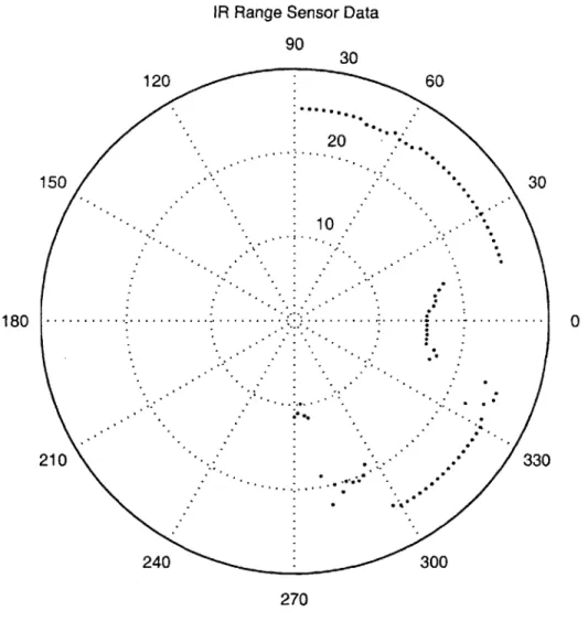
IR Range Sensor Data 90 30 120 60 20 150 -- 30 - 10 1 8 0 .. .. .- -. - --- -..--.---. - - - - .- - . -- 0 210 - ' 330 240 300 270 Angle/Distance (inches)
Figure 4-5: Graph of IR range sensor data
Figure 4-6: IR range sensor attached to position controlled servo motor
several other techniques (actually implemented by other students) are discussed in section 5.1. The example robot wanders the environment and updates and maintains a map of what it sees (within a 15 inch radius). Based on this information, the robot plans a best path to where it thinks the target is (based on it IR beacon detector and triangulation). Moving around in the environment updates the map, so the path needs to be updated regularly. Obstacle avoidance is achieved by path planning rather with a reactive control system (which would veer away from an obstacle it might be near and veer towards open space or its target goal).
4.6.2
Localization
Localization (determining the position) of the robot is mainly achieved using encoder odometry. The distance that each drive wheel travels is integrated to establish a location and angle in a global coordinate system defined by the starting position of the robot. While encoder odometry is subject to accumulated error, on a hard surface over a small area, the error does not introduce too large of a problem. Over around ten full rotations of the robot, the error in the angle measured was only several degree;
over traveling a distance of approximately 10 feet, the error in distance was less than 2 inches. However, the odometry based localization can also be supplemented with other forms of localization, such as landmark detection or triangulation, to improve accuracy.
Triangulation based solely on angle to multiple beacons cannot provide a com-pletely constrained solution to position; it can only provide a line on which the robot must lie (using the angles in set of linear equations leaves the system under con-strained by one variable). However, knowing distance to one or more beacons can resolve this problem, and allows for position to be determined absolutely (distance constrains the previous solution of a line to a single point). Unfortunately, in such a small environment and using IR, determining distance is extremely difficult (in a real system, one might use RF at large distances, so time of flight can be estimated to provide distance). But, position constrained to a line still allows the error introduced
by odometry to be reduced.
4.6.3
Navigation
Robot navigation can be achieved using the map built by the robot and planning a path in the map. The map maintains the occupancy of space and the robot's path with one inch resolution. As the robot moves around the environment, new information is accumulated and added into the map. To determine a path to a specific target
(x,y) location in the environment, each coordinate in the map is supplemented with
a straight-line distance to the target and the configuration space [10] of the map is determined. An A* search [13] (using the distance as an under-estimate) can then be carried out by the robot to determine the best path to the target given its current knowledge of the state of the environment.
The configuration space of the map could be used to simplify the search procedure. It essentially enlarges all obstacles in the map based on the geometry of the robot so that the robot can be represented in the map as a single point, rather than its actual shape. Calculating the configuration space is efficient because the robot is perfectly symmetrical; if it were not, a configuration space for specific angles of rotation of the
robot would need to be calculated.
Because the map resolution is only one inch, the map size is relatively small, and consequently, a distance from every coordinate in the map to the target can be cal-culated quickly. This provides an underestimate to the target from each point which is guaranteed to be less or equal to the actual distance (an "admissible heuristic").
To determine the best path to a goal, the robot would search the map from its current location outward, expanding only the best paths (according to the under-estimate). Paths are considered to be adjacent, non-occupied coordinates in the map grid (configuration space).
Figure 4-7: A example map created by a robot: a grid of one inch resolution, with the robot taking a path around a target surrounded by a 4 ft. square of walls; the dark points represent the robot's path, while the lighter points are the obstacles it detects
Chapter 5
Results
5.1
Coursework
To test the platform, we held a month-long course in advanced autonomous robot design using the platform. However, in addition to providing a thorough test of the platform, we were interested in what capabilities students would use or need, as well as the type of algorithms and control systems they would design, and how accessible and easy to use the platform was. The results of the course allowed us design the next revision of the platform more effectively.
The course was aimed towards undergraduate students with some experience in robot design or embedded systems. The students ranged in experience from none (freshman with no design/engineering course, but basic programming skills) to mod-erate (seniors with high level design/programming courses, along with some exposure to robotics and AI). Three teams of between two and four members met every day for a month to design and build an autonomous robot that could interact in the en-vironment. Teams mainly used basic velocity and position control systems to move, odometry to localize, and methods like reactionary control and gradient descent to navigate. The most successful team used an IR range finder and IR beacon detector to weight direction of movement, and then turned and moved in the best direction, and repeated the process.
The platform performed very well during the test course. All the teams learned
to program and debug code for the platform quickly, even the ones who had not used
gdb before. The capabilities of the platform were never exceeded (in terms of speed
or memory) and the kernel did not seem to introduce any bugs into the code. The controller board itself proved to be robust, in that during the month of intense use, none of the boards broke in any way, nor did any components need to be replaced or modified. The course did, however, reveal several minor flaws of the board. These problems included simple things like the position of the reset button and the lack of dedicated servo motor connectors, to more severe ones like the fact that more than two servo motors drew enough current in a transient to reset the board.
5.2
Future Work
5.2.1
Platform Fixes
The already planned next revision to the board includes several fixes to the controller board. Rather than using a single regulated supply to both the controller board and servo motors, we will provide separately regulated supplies which can be driven from a single supply or two independent supplies. The servo motor supply will be regulated through a linear regulator which will be able to deal with the current transients and, will, consequently, not effect the rest of the controller board. Additionally, dedicated servo motor drivers will be added, conforming to the standard servo motor connector. Aesthetically, several minor things need to be changed: the position of the reset button needs to be relocated to be more accessible and header needs to be made female to prevent accidental shorting.
5.2.2
Platform Enhancements
The controller board could very easily be enhanced. We plan to upgrade the current Hitachi 7044 SH2 112-pin TQFP microcontroller to a 7045 SH2 144-pin TQFP. This new part runs at a substantially higher clock rate (60 MHz, instead of 30 MHz) and provides many more
I/O
pins. The Altera CPLD can also be upgraded easily. Alarger part will provide more capabilities and more I/O. On the other hand, for cost reasons, the CPLD could be removed entirely. Other options for the controller board include using a battery backed SRAM instead of DRAM, which would be faster, but more expensive. Additionally, an external FLASH could be added to allow a persistent form of memory for instruction code, rather than using the SH2's on-board
FLASH (which is only programmable hundreds of time; external FLASH could be
bought that can endure thousands of cycles). Eventually, the main components of the board may be switched to 3.3V parts, which are more readily accessible and generally cheaper. However, this would require a split power supply, as most sensors and external components would still require a 5V power supply.
5.2.3
Environment Generalizations
The goal of our environment was to provide a realistic environment without some of the mechanical problems one might find in the real world. However, the environment does not provide all of the capabilities the real world might be able to. For instance, robots do not have a measure of distance to the beacons (navigational or targets) and so cannot triangulate completely.
5.2.4
Robot Enhancements
The robots designed can always be improved. However for demonstration purposes we would like to provide a more robust and faster velocity and position control system, as well as some more refined methods of navigation and mapping. We are considering adding a cheap CMOS imaging sensor and doing simple image processing to find obstacles, rather than using an IR beacon detector. While the processor would not be capable of doing anything as sophisticated as stereo, it would be able to detect edges or lines in a static image.
Chapter 6
Conclusion
We have designed a cost-effective, simple, yet powerful platform capable of controlling an autonomous robot. In addition, we have developed an environment to simulate but simplify real world condition, and provided an example robot for this environ-ment. The platform and environment were tested by students in a month long course centered around building robots to interact in the environment. During this course, students were able to quickly prototype a robot as well as develop some sophisticated control and navigation algorithms.
Another revision of the platform is planned to fix the minor problems revealed
by the course and the example robot will be improved for the next course. However,
overall, the platform performed extremely well. Its capabilities were not outstripped and the cost was acceptable to the students. The environment provided a conceptually difficult but mechanically simple problem to motivate intelligent autonomous robots. The students spent most of their time trying to solve problems like navigation and localization, and less time designing control systems or deciding on how to grab the targets.
The platform has many applications in both research and educations, and has already been accepted by other robotics groups who need a cost-effective controller board. 6.270, MIT's Autonomous Lego Robotics Contest consisting of 50 teams of three to four students, will be using the platform next term and we are currently designing the next revision to accommodate their needs. Several other academic
institutions are interested in the platform after [9] was presented at the AAAI Sym-posium on Robotics and Education. Acroname, a popular robotics kits and parts distributer has also expressed strong interest in marketing the platform, and will be making it available to the public in the future.
Overall, the platform's simple interface and standard development environment make it easy to learn and use. And its low cost but high performance allow both students and researchers to quickly prototype a mobile robot and implement useful algorithms.
Appendix A
Platform Specifications
1. 30 MHz, 32-bit RISC Microcontroller (Hitachi SH7044)
2. 2MB DRAM (ISSI IS41C16105)
3. 2 Dedicated quadrature phase encoder inputs
4. 4 High current motor drivers (2 Allegro UDN2998W motor drivers (dual H-bridges))
5. 4 Dedicated servo motor outputs
6. 7 Mid-speed analog inputs (10 us conversion)
7. 16 Low-speed analog inputs (Maxim 306 16-to-1 analog mux)
8. 16 Digital inputs/outputs (dedicated 4 switch dip switch and 2 push buttons) 9. LCD interface
10. On-board reprogrammable logic device (Altera 7000S CPLD) 11. Serial interface (Maxim 202E RS-232 transceiver)
12. Supports a single motor/board power supply (National LM2595 switching power regulator)
13. Supports GNU toolchain (gcc, gdb, etc.)
Appendix B
Schematics/Layout
B.1
Annotated Platform Schematics
These subsections each refer to one page in the attached schematics.
B.1.1
Power
All of the components on the controller board require a power voltage of 5V; however DC motors like the ones being used are generally run at 12-24V. So the board is
fed with 12V to power the motors and is regulated to 5V to power the board. This page shows the power connector (supplying the 12V to the board), power switch, regulator (regulates the power from 12V to 5V), power LED, and power filtering capacitors. We use a switching power regulator because we found a linear regulator which dissipates energy through heat was too inefficient (40% efficiency); however, the switching supply requires many more external components and does not deal with current transients as well.
B.1.2
Controller
This page shows the Hitachi SH2 (SH7044) microcontroller (MCU) (U3) and some surrounding circuitry. The jumpers/switch which determine the programming/run mode of the MCU are in the lower left. There is also a reset circuit (using the
DS1233) which prevents the reset button from resetting the chip incorrectly. The
chip (Y1) above the MCU is its clock (crystal oscillator); it provides a 7.237MHz clock to the chip. The chip, based on its mode (selected by the jumpers) can be run at this clock speed times 1, 2, or 4. The MCU ups the clock speed by using a phase locked loop.
The Hitachi SH2 has many on-board peripherals, including an A/D, PWM output, and counter capture ports. The analog to digital converter (A/D) can discritize an analog signal between OV and 5V to a 10-bit number. There are 8 A/D inputs, however the MCU only has one A/D which it uses to convert each signal in series. The PWM output is a Pulse Width Modulated signal - a pulse signal with a constant (settable) frequency, and a changeable duty cycle ("width"). The counter capture port simply counts rising or falling (or both) edges from a pulse signal on the pin.
B.1.3
Serial I/O
The controller board can communicate to a PC or other device using a serial port; however the standard serial protocol (RS-232) uses a +/-12V signal. Because the board uses a 5V signal voltage, this needs to be converted to +/-12V. This is done using a charge pump (MAX203E; a more common part is the MAX202 or MAX232; these are all made by Maxim). The chip simply converts a 0/5V signal to a -12/+12V signal.
B.1.4
DRAM
This is the 2MBytes of DRAM that the MCU uses. There is a 16 bit data interface to the MCU, and consequently, 10 bits of address. The Hitachi MCU has a built in
DRAM controller which manages the RDWR, /RAS, and /CAS lines.
B.1.5
Analog Input
Although the SH2 provides 8 analog input pins, we have added an analog multiplexer to multiplex 16 more analog signals into one pin on the SH2. Getting the data from