Decoherence-free neutron interferometry
The MIT Faculty has made this article openly available.
Please share
how this access benefits you. Your story matters.
Citation
Pushin, D. A., M. Arif, and D. G. Cory. “Decoherence-free neutron
interferometry.” Physical Review A 79.5 (2009): 053635.(C) 2010 The
American Physical Society.
As Published
http://dx.doi.org/10.1103/PhysRevA.79.053635
Publisher
American Physical Society
Version
Final published version
Citable link
http://hdl.handle.net/1721.1/51344
Terms of Use
Article is made available in accordance with the publisher's
policy and may be subject to US copyright law. Please refer to the
publisher's site for terms of use.
Decoherence-free neutron interferometry
D. A. Pushin,1,
*
M. Arif,2 and D. G. Cory11
Massachusetts Institute of Technology, Cambridge, Massachusetts 02139, USA
2
National Institute of Standards and Technology, Gaithersburg, Maryland 20899, USA 共Received 10 September 2008; published 21 May 2009兲
Perfect single-crystal neutron interferometers are adversely sensitive to environmental disturbances, particu-larly mechanical vibrations. The sensitivity to vibrations results from the slow velocity of thermal neutrons and the long measurement time that are encountered in a typical experiment. Consequently, to achieve a good interference solutions for reducing vibration other than those normally used in optical experiments must be explored. Here we introduce a geometry for a neutron interferometer that is less sensitive to low-frequency vibrations. This design may be compared with both dynamical decoupling methods and decoherence-free subspaces that are described in quantum information processing. By removing the need for bulky vibration isolation setups, this design will make it easier to adopt neutron interferometry to a wide range of applications and increase its sensitivity.
DOI:10.1103/PhysRevA.79.053635 PACS number共s兲: 03.75.Dg, 03.65.⫺w, 42.50.⫺p
I. INTRODUCTION
Neutron interferometry is one of the most precise tech-niques used to test the postulates of quantum mechanics, and it is also one of the most important and precise techniques used to measure low-energy neutron cross sections 关1兴.
Al-though the fundamentals of neutron interferometry are easily recognizable from common optics, the slow velocity of neu-trons共1680 m/s for the 2.35 Å neutrons used in this study兲 and low count rates at the detector共1000/min兲 demand novel solutions. The most important of these was the development of multiblade single-crystal interferometery which enables high contrast to be observed with only limited beam align-ment 关2,3兴. The challenge remains however of making the
experiment robust against mechanical vibrations 关4,5兴. A
typical single-crystal interferometer has path lengths of 10 cm with a typical 50 s travel time of neutrons in the sys-tem. Small-amplitude low-frequency vibrations may signifi-cantly degrade the contrast. Here we propose a solution to robust interferometry based on a four-blade single-crystal ge-ometry that reduces errors introduced by vibrations.
II. INTERFEROMETER SCHEMATIC
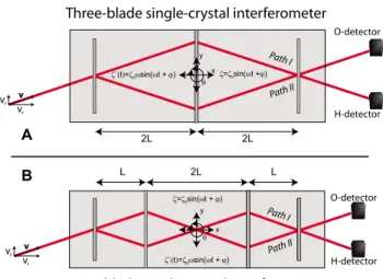
The most common three-blade geometry for a perfect-crystal neutron interferometer 共NI兲 关1兴 is shown in Fig.1共a兲
along with the four-blade configuration关Fig.1共b兲兴 that is less sensitive to low-frequency vibrations.
In the three-blade case the neutron beam, coming from the left, is coherently split into two paths by the first blade via Bragg scattering. After being reflected by the second blade, these two paths are recombined at the third blade. The result-ant interference is observed at the O- and H-detectors. Note that we align the y coordinate parallel to the Bragg planes and the x coordinate is perpendicular to the Bragg planes. In the four-blade case the situation is nearly identical with the significant difference that the paths are reflected and cross
each other without interfering at the center of the interferom-eter; i.e., without a blade there is no mixing of the states.
It is sufficient to take a simple model for noise and to consider vibrations as sinusoidal oscillations around the cen-ter of mass of the single crystal, which we write as
PathII Path I Three-blade single-crystal interferometer
PathII Path I
Four-blade single-crystal interferometer
A B 2L 2L 2L L L y v v v x 0 0 0 0 y v v v x y x y x O-detector H-detector O-detector H-detector
FIG. 1. 共Color online兲 共a兲 A schematic diagram of the three-blade neutron interferometer. A neutron beam共with neutron veloc-ity v兲 comes from the left, is split by the first blade, is diffracted on the second blade, and recombines at the third. After passing through the interferometer, the beam is captured by the O- and H-detectors. We model vibrations as oscillations of and around the center of mass of the interferometer, as共t兲=0sin共t+兲, where could be
y 共transverse vibrations兲, x 共longitudinal vibrations兲, and 共rota-tional vibrations兲. In order to compare oscillations between the three- and four-blade devices the distance between the blades is set equal to 2L.共b兲 A schematic diagram of the proposed interferometer with four blades. Instead of one diffracting blade here we have two, which reverses the neutron paths in order to compensate for vibra-tions. We will compare the performances using the same vibration modes with the same amplitudes. Note that for the three-blade in-terferometer the O-detector has the maximum contrast and in the four-blade interferometer the H-detector has the maximum contrast.
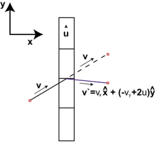
共t兲 =0sin共t +兲. 共1兲 For we can specify any coordinates x, y, and z, or any angles 共such as , the rotation around z axis兲. In order to motivate the discussion we adopt a simple model for the neutron-blade interaction that includes all of the necessary physics. The interaction is that of bouncing of a small par-ticle共neutron兲 from a moving heavy wall 共the blade兲 where the particle is reflected. When the particle is transmitted there is no interaction共Fig.2兲. We use conservation of momentum
and energy to calculate the neutron’s change in velocity after bouncing. We require a small enough amplitude and low enough oscillation frequency that the modified momentum of the neutron still satisfies the Bragg condition.
Vibrations thus modify the neutron velocities and change the path length of the neutron inside the interferometer关6–9兴.
Using these approximations, it is clear that vibrations along every axis except the z coordinate will reduce the in-terferometer contrast. The z component of neutron velocity is zero and the path lengths are independent of crystal vibration along the z axis at this level of approximation.
III. VIBRATIONS ALONG THE y AXIS
We first consider vibrations along the y axis. The measure of the quality of the interferometer is its contrast, so we calculate and plot the contrast versus the frequency of oscil-lations. The four-blade version returns higher contrast by compensating with the third blade for momentum change introduced by vibration of the second blade. We expect this compensation to be most precise for low-frequency vibra-tions.
A. Three-blade interferometer
Assume that the neutron hits the first blade of interferom-eter at the time t = 0. We rewrite Eq.共1兲 for vibrations along
the y axis where is a random phase between the arriving neutron and the vibrating blade,
y共t兲 = y0sin共t +兲. 共2兲 The velocity of the interferometer at the time t is
uy共t兲 =
dy共t兲
dt = y0cos共t +兲. 共3兲
At time t = 0, the velocity of the interferometer along the
y coordinate is uy共0兲=y0cos. Conservation of momen-tum and energy at the moment t = 0 implies that the velocity of the transmitted neutron does not change, while the re-flected neutron’s velocities are vrefl共0+兲=vxxˆ −关vy− 2uy共0兲兴yˆ.
The phase difference for the neutron between path I and
path II is
⌬⌽ = ⌽共path II兲 − ⌽共path I兲 = 1 ប
冕
path IIpds −1
ប
冕
path Ipds,
共4兲 where p is the momentum of the neutron and s is the path-length vector along which the neutron is moving.
For the neutron to travel between the first two blades takes a time t = 2L/vx= 2. The contrast depends on the total
phase difference between the paths. Notice that under these assumptions the two paths cross the third blade at the same spot and the travel time along these paths remains 4. So, the loss in contrast seen in the presence of vibration is not due to the finite coherence length of the interferometer but rather is due to the extra phase shifts introduced by the vibrations.
Using these we find ⌬⌽共兲 = 16mn
ប 关vy− uy共0兲兴关uy共2兲 − uy共0兲兴. 共5兲
If we assume that uy共t兲 is slowly varying on the scale
of 2 共or Ⰶ1兲, we can approximate the expression
uy共2兲−uy共0兲 as a derivative of uy共t兲,
⌬⌽共兲 = 16mn
ប 2关vy− uy共0兲兴2
冏
duy共t兲
dt
冏
t=. 共6兲The intensity at the O detector is
IO共兲 = 1 + cos关⌬⌽共兲 +兴 共7兲
and depends on the random phase. An experimental phase
is introduced by a phase flag. We average the intensity over random phase :
IO共兲 =
1 2
冕
02
兵1 + cos关⌬⌽共兲 +兴其d. 共8兲 The contrast C as usual is defined as
C =max兵I共兲其 − min兵I共兲其
max兵I共兲其 + min兵I共兲其, 共9兲 where we vary the phase to find the max or min.
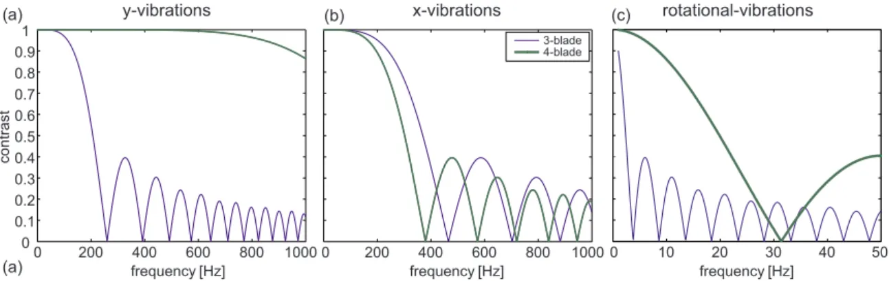
Fig.3共a兲shows the dependence of the contrast Cyon the
frequency of vibrations along the y axis for the three-blade interferometer. The contrast was calculated for L = 5 cm, a neutron velocity of v = 2000 m/s, and vibration amplitudes
of y0= 0.1 m. Here we observe that the contrast starts to decrease near 100 Hz. u v v v`=v x + (-v +2u)y x y x^ y ^
FIG. 2. 共Color online兲 A schematic diagram of the neutron scat-tering from a blade of the neutron interferometer. Due to the crystal movement, the reflected neutron’s momentum is modified. For the transmitted case, the momentum remains unaltered.
PUSHIN, ARIF, AND CORY PHYSICAL REVIEW A 79, 053635共2009兲
B. Four-blade interferometer
As in the three-blade interferometer case, we derive ex-pressions for the phases the neutron acquires while traveling along the two interferometer paths. Here, the time for the neutron to travel between the first two blades is = L/vx.
Note that the detector corresponding to the neutron paths with equal number of reflections for the three-blade interfer-ometer is O-detector and for the four-blade interferinterfer-ometer it is H-detector.
Between the first blade and the second, the phases are identical to the three-blade interferometer case except that 2L changes to L. The phase difference between path II and path
I is
⌬⌽共兲 = 8mn
ប 关uy共0兲 − vy兴关2uy共0兲 − 3uy共兲 + uy共3兲兴.
共10兲 Again, as for the case of three-blade interferometer, we as-sume that the function uy共t兲 is slowly varying on the scale of
共orⰆ1兲 and we rewrite the phase change in terms of a derivative, ⌬⌽共兲 = 16mn ប 2关vy− uy共0兲兴
冋
冏
duy共t兲 dt冏
t=/2−冏
duy共t兲 dt冏
t=2册
= 16mn ប 3关vy− uy共0兲兴 3 2冏
du2y共t兲 d2t冏
t=5/4 . 共11兲Notice that the linear term drops out. This is the source of the protection against vibrations. The contrast comparison we make is the O-beam of the three-blade interferometer to the H-beam of the four-blade interferometer. The intensity at the H-detector is
IH共兲 = 1 + cos关⌬⌽共兲 +兴 共12兲
and depends on the random phaseof vibration. Again we average the intensity over this random phase:
IH共兲 =
1 2
冕
02
兵1 + cos关⌬⌽共兲 +兴其d. 共13兲
We obtain the contrast using Eq.共9兲. In Fig.3共a兲we plot the frequency dependence of the contrast for the four-blade interferometer. Notice that paths I and II cross the fourth blade at the same spot. From Fig.3共a兲we clearly see that the four-blade interferometer is predicted to be much less sensi-tive to y vibrations.
IV. VIBRATIONS ALONG THE x AXIS
In the case of vibrations along the x axis the momentum of the neutron is not modified共see Fig.2兲. However the path
length changes depending on the phase of the oscillations at t = 0.
Here the contrast is primarily limited by the neutron co-herence length of 1/⌬k. The four-blade geometry does not protect against this and indeed the influence of a finite co-herence length is slightly worse due to the noise being intro-duced since the intervals between blades are changed by the vibrations. In the three-blade case there are two such inter-vals, while in the four-blade case there are three. So with finite ⌬k the more blades there are, the worse the noise is. However, since the acceptance of the NI is small,⌬k is small and this contribution to the noise is small.
Here we calculate just the contribution to the loss in con-trast from the phase shift introduced by vibrations along x axis. The vibrations along the x axis are
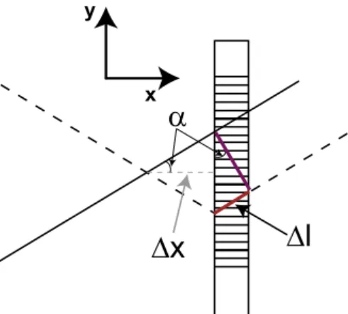
x共t兲 = x0sin共t +兲. 共14兲 In this case the phase shift is due to the paths crossing at a point displaced from ideal as shown in Fig.4. Once we find ⌬x for each interferometer, then ⌬l=2⌬x tan␣sin␣and the phase difference is
⌬⌽共兲 =mn
ប v⌬l. 共15兲
For the three-blade interferometer, we have= L/vxand
⌬x ⬇ x共4兲 − 2x共2兲 + x共0兲, 共16兲 where we neglect distance x共2兲−x共0兲 共⬍1 m兲 in compari-son with L共⬎1 cm兲. For the four-blade interferometer
0 200 400 600 800 1000 0 0.1 0.2 0.3 0.4 0.5 0.6 0.7 0.8 0.9 1
frequency [Hz] frequency [Hz] frequency [Hz]
ts art n oc 0 200 400 600 800 1000 3-blade 4-blade x-vibrations y-vibrations rotational-vibrations 0 10 20 30 40 50 (a) (c) (a) (b)
FIG. 3. 共Color online兲 共a兲 Contrast due to vibrations along the y axis. 共b兲 Contrast due to vibrations along the x axis. 共c兲 Contrast due to rotational vibrations around z axis and the center of mass. Note that the scale of the frequency axis in 共c兲 is different from those shown in 共a兲 and 共b兲.
⌬x = x共4兲 − 4x共兲 + 3x共0兲. 共17兲 Using these ⌬x we can get ⌬⌽, substitute obtained ⌬⌽ to find intensities, and average the intensities over differentto obtain the contrasts.
Figure 3共b兲 shows the contrast dependence on the fre-quency of vibrations along the x axis. This should be viewed as an upper bound on the predicted contrast. The message is that vibrations along the x axis are not very important even though the four-blade design is somewhat more sensitive to them than is the three blade design. In the final analysis the four-blade design is predicted to have better overall perfor-mance.
V. ROTATION AROUND THE z AXIS
These vibrations are expected to be the most limiting since the neutron interferometer has such a small acceptance angle. In the case of rotational vibrations, we rewrite the oscillation in terms of the angle around the z axis,
共t兲 =0sin共t +兲. 共18兲 For small angles, rotational vibrations can be considered as translational vibrations, i.e.,⌬r=rⴱ, where r is the dis-tance from the blade to the center of rotation.
A. Three-blade interferometer
In the three-blade interferometer, the center of rotation is also the center of mass and the center of the middle blade. For the point 关see Fig.1共a兲兴 where the neutron path crosses the blades, the rotational vibrations can be modeled as vibra-tion along the y axis for the first and last blades and along the
x axis for the path crossing the middle blade. In this case, the
interaction with the middle blade does not change the veloc-ity of the neutron. At the first blade we have a change in the momentum of the reflected beam and no change for the transmitted neutrons,
vpath I共t = 0+兲 = vxxˆ +vyyˆ, 共19兲
vpath II共t = 0+兲 = vxxˆ +关− vy+ 2u1y共0兲兴yˆ, 共20兲
where u1y共t兲=2L0sin共t +兲 velocity of the first blade in the yˆ direction.
The phase difference between the two paths is ⌬⌽共兲 = ⌽共path II兲 − ⌽共path I兲 =mn
ប 关兩vpath I兩2 −兩vpath II兩2兴4= 8 mn ប L0sin关2L0sin −vy兴4, 共21兲 where= L/vx.
Substituting this difference in phase into Eq. 共7兲 for the
O-beam intensity and averaging, we find the frequency de-pendence of contrast共9兲. Fig.3共c兲shows this contrast. As an amplitude of vibrations0we used 1 rad. The value for the amplitude comes from the current NIST setup, where a vi-bration isolation table is controlled to this level关5兴.
B. Four-blade interferometer
In the four-blade interferometer the center of rotation and the center of mass coincide between the blades. For points 关see Fig.1共b兲兴 where the neutron path crosses the blades, the rotational vibrations are modeled as vibrations along the y axis. As in the three-blade case the vx component of the
neutron velocity does not change. The velocities are modi-fied as follows. For path I: vy共I:1 → 2兲 = vy, 共22兲 vy共I:2 → 3兲 = − vy+ 2
冑
L2+共vy兲20cos共+兲, 共23兲 vy共I:3 → 4兲 = vy− 2冑
L2+共vy兲20关cos共+兲 + cos共3+兲兴, 共24兲 where= L/vxand the sign of the last cosine term is positivebecause the oscillations of the second and the third blades have aphase-shift difference.
For path II:
vy共II:1 → 2兲 = vy+ 202L cos, 共25兲
vy共II:2 → 3兲 = − vy共II:1 → 2兲 + 2
冑
L2+共vy兲20cos共+兲, 共26兲
vy共II:3 → 4兲 = − vy共II:2 → 3兲 − 2
冑
L2+共vy兲20cos共3+兲. 共27兲
The phases along each path are as follows. For path I:
⌽共I:1 → 2兲 =mn
ប v2, 共28兲
x y
FIG. 4. 共Color online兲 A schematic diagram of the neutron ar-riving to the third blade. Due to the crystal movement, the paths of the neutron will not recombine at the ideal point but at⌬x away from the third blade.
PUSHIN, ARIF, AND CORY PHYSICAL REVIEW A 79, 053635共2009兲
⌽共I:2 → 3兲 =mn ប 关vx2+vy共I:2 → 3兲2兴2, 共29兲 ⌽共I:2 → 3兲 =mn ប 关vx 2 +vy共I:3 → 4兲2兴. 共30兲
For path II:
⌽共II:1 → 2兲 =mn ប 关vx 2 +vy共II:1 → 2兲2兴, 共31兲 ⌽共II:2 → 3兲 =mn ប 关vx 2 +vy共II:2 → 3兲2兴2, 共32兲 ⌽共II:2 → 3兲 =mn ប 关vx 2 +vy共II:3 → 4兲2兴. 共33兲
The phase difference is
⌬⌽共兲 = ⌽共II:1 → 2兲 + ⌽共II:2 → 3兲 + ⌽共II:3 → 4兲 −关⌽共I:1 → 2兲 + ⌽共I:2 → 3兲 + ⌽共I:3 → 4兲兴.
共34兲 As before, we can find the IH intensity at the H detector,
average it over the random phase, and extract the contrast. This contrast dependence on the frequency of rotational vi-brations is plotted in Fig.3共c兲. We see that for these rotations the four-blade interferometer design is significantly more ro-bust than the three-blade. Notice that for rotational vibrations the first moment of the loss of contrast is not equal to zero; all vibrations contribute to the loss of contrast.
VI. CONCLUSION
Our model reconstructs the situation that is normally seen in neutron interferometry. Vibrations we use in our simula-tions 共with amplitude of 10−7 m in translation兲 produce changes in the incident angle of the neutron of much less than the acceptance angle of the crystal共Ⰶ5⫻10−6 rad兲 and of a similar order for the 50 Hz frequency range previously measured 关5兴. In order to exceed the acceptance angle the
amplitude of vibrations would have to be bigger than 50 m.
Note that small angle vibrations around the x axis will be similar to the translational vibrations along the y axis, and small angle vibrations around y will be similar to the trans-lational vibrations along x. As mentioned before, vibrations along the z axis do not influence the contrast.
Taken together these results bring us to the four-blade experimental geometry for neutron interferometer. Although
the four-blade design leads to a loss of half of the neutron intensity, we can make up for this loss with a more robust, small system that can be moved closer to the beam break. We thus regain and even increase the final neutron intensity at the detectors. In order to achieve high contrast the proposed four-blade interferometer system still requires excellent tem-perature stability 关10兴.
The robust nature of the four-blade interferometer can also be understood as a result of dynamical decoupling or decoherence-free subspace 共DFS兲. The dynamical decou-pling analogy关11,12兴 is easiest to see; the third set of blades
acts to undo the change in momentum introduced by the second blades. Provided that the noise共motion of the NI兲 is the same when the neutron encounters both the second and third blades, then the momentum error is completely re-moved.
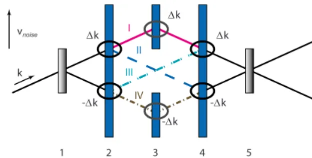
The DFS 关13–15兴 picture can be seen if two additional
paths are considered. Now we have four paths and an inter-ferometer that acts over SU共4兲; see Fig. 5. The outer two paths are sensitive to the noise and the inner two are isolated from it. We are presently installing a five-blade interferom-eter to test these predictions.
ACKNOWLEDGMENTS
Support provided by NIST is gratefully acknowledged. The authors are grateful for discussions with D. L. Jacobson, R. Laflamme, B. Levi, and C. Ramanathan. Discussion with S. A. Werner about an earlier idea of a four-blade interfer-ometer for use in gravity and spin-rotation关7兴 experiments is
gratefully appreciated. 1 2 3 4 5 I II III IV ∆k ∆k -∆k ∆k -∆k -∆k k vnoise
FIG. 5. 共Color online兲 A schematic representation of the robust four-blade interferometer embedded in a five-blade interferometer. The overall interferometer operates over SU共4兲 and can be thought of as a tensor product space of two qubits. A simple abstraction of the noise generators is⫾⌬k at each internal reflection 共there is no noise at the first and final blades兲. When we look over the entire path, two paths have noise共I and IV兲, and two paths do not have noise 共II and III兲. The noise generator is proportional to sgn共kជ·vជnoise兲⌬k for each reflection internal to NI.
关1兴 H. Rauch and S. A. Werner, Neutron Interferometry 共Oxford University Press, New York, 2000兲.
关2兴 H. Rauch, W. Treimer, and U. Bonse, Phys. Lett. A 47, 369 共1974兲.
关3兴 W. Bauspiess, U. Bonse, H. Rauch, and W. Treimer, Z. Phys. 271, 177共1974兲.
关4兴 A. Shimony and H. Feshbach, Physics As Natural Philosophy 共MIT Press, Cambridge, MA, 1987兲.
关5兴 M. Arif, D. E. Brown, G. L. Greene, R. Clothier, and K. Lit-trell, Proc. SPIE 2264, 20共1994兲.
关6兴 C. G. Shull and N. S. Gingrich, J. Appl. Phys. 35, 678 共1964兲. 关7兴 B. Buras and T. Giebultowicz, Acta Crystallogr., Sect. A:
Cryst. Phys., Diffr., Theor. Gen. Crystallogr. 28, 151共1972兲. 关8兴 M. Dresden and C. N. Yang, Phys. Rev. D 20, 1846 共1979兲. 关9兴 B. Mashhoon, Phys. Rev. Lett. 61, 2639 共1988兲.
关10兴 D. A. Pushin, M. Arif, M. G. Huber, and D. G. Cory, Phys. Rev. Lett. 100, 250404共2008兲.
关11兴 L. Viola and S. Lloyd, Phys. Rev. A 58, 2733 共1998兲. 关12兴 L. Viola, E. Knill, and S. Lloyd, Phys. Rev. Lett. 82, 2417
共1999兲.
关13兴 P. Zanardi and M. Rasetti, Phys. Rev. Lett. 79, 3306 共1997兲. 关14兴 L.-M. Duan and G.-C. Guo, Phys. Rev. Lett. 79, 1953 共1997兲. 关15兴 D. A. Lidar, I. L. Chuang and K. B. Whaley, Phys. Rev. Lett.
81, 2594共1998兲.
PUSHIN, ARIF, AND CORY PHYSICAL REVIEW A 79, 053635共2009兲