Design and Performance Evaluation of an Electric Go-Kart and Custom
Permanent Magnet Brushless DC Motor
by
Eli Marc Davis
Submitted to the
Department of Mechanical Engineering
in Partial Fulfillment of the Requirements for the Degree of
Bachelor of Science in Mechanical Engineering
at the
Massachusetts Institute of Technology
June 2012
© 2012 Eli Marc Davis. All rights reserved.
The author hereby grants to MIT permission to reproduce and to distribute
publicly paper and electronic copies of this thesis document in whole
or in part in any medium now known or hereafter created.
Signature of Author:
Department of Mechanical Engineering
May 22, 2012
Certified by:
Daniel Frey
Associate Professor of Mechanical Engineering and Engineering Systems
Thesis Supervisor
Accepted by:
John H. Lienhard V
Samuel C. Collins Professor of Mechanical Engineering
Undergraduate Officer
3
Design and Performance Evaluation of an Electric Go-Kart and Custom
Permanent Magnet Brushless DC Motor
by
Eli Davis
Submitted to the Department of Mechanical Engineering
on May 22, 2012 in Partial Fulfillment of the
Requirements for the Degree of
Bachelor of Science in Mechanical Engineering
ABSTRACT
This undergraduate thesis documents the design considerations and specifications of building a
personal battery-powered go-kart. This includes designing and building a custom brushless DC
motor for use in the drivetrain. Details of the fabrication and assembly processes are included
for reference. The motor was not finished in time to be able to be tested, but the performance of
the go-kart has been estimated through scientific calculations.
Thesis Supervisor: Daniel Frey
5
Acknowledgements
I would like to thank Professor Daniel Frey, my thesis advisor, for giving me opportunities
which positively shaped my undergraduate career. I would also like to thank everyone who gave
me advice and tips throughout this project, especially Charles Guan and Shane Colton, both of
whom have an unparalleled understanding of personal electric vehicle design.
I am also grateful for the various machine shops and workspaces in which I worked on this
thesis. These include the International Design Center at MIT, the MIT Electronic Research
Society, the Edgerton shops, and Pappelardo Lab.
7
Table of Contents
Abstract
3
Acknowledgements
5
Table of Contents
7
List of Figures
8
1. Introduction
9
1.1 Motivation
9
1.2 Goals
9
2. Eli-Kart
10
2.1 Frame
10
2.2 Steering
11
2.3 Drivetrain
13
3. Custom Motor
15
3.1 Design constraints and calculations
15
3.2 Mechanics and Fabrication
18
4. Predictions and Conclusions
21
4.1 Efficiency
21
4.2 Conclusions
22
8
List of Figures
Figure 2-1:
Picture of the frame.
10
Figure 2-2:
Picture of the steering wheel.
11
Figure 2-3:
Picture of the steering connector.
11
Figure 2-4:
Diagram of Ackermann steering geometry.12
Figure 2-5:
Picture of steering block and tie rod connection.13
Figure 2-6:
Picture of motor mount.14
Figure 3-1:
CAD sketch showing the outer edge of the motor’s profile.16
Figure 3-2:
CAD sketch showing ideal close packing of wire around a stator tooth.17
Figure 3-3:
Graphic showing flux density in the motor cross-section.17
Figure 3-4:
Picture of stator assembly.18
Figure 3-5: Picture of all the magnets in position with epoxy filling the gaps.
19
Figure 3-6:
Picture of shaft connector end.20
9
1. Introduction
1.1 Motivation
My motivation for choosing this topic as my thesis stems from a variety of interests. Ever since I got my driver’s license, learning about automobiles has been a passion of mine. Along with watching shows about cars and frequently visiting online automobile blogs, I occasionally helped my father maintain the family cars at the high school auto shop where he works. After my second year at MIT, I joined the Electric Vehicle Team where I helped with the battery-electric conversion of the Ford CD3 platform. As I worked with the team over the summer, I was exposed to a plethora of other student groups and personal projects from MIT’s Formula SAE racing team to the MIT Electronic Research Society. Since then, I have always wanted to build my own vehicle but never could find the time between classes and personal obligations.
During my senior year, I began to design to formulate ideas for an electric go-kart. At that point, the required thesis for undergraduates pursuing a full mechanical engineering degree was far from my motivation. However, as graduation creeped closer and closer, it became obvious that my goal of building my own vehicle would only get done if I committed to it as my thesis project. I wanted to combine my hands-on experience with a modern project that represented my talents and personality. Thanks to support from several friends, I was able to accomplish my goal.
1.2 Goals
For this project, I wanted to demonstrate my accumulated engineering knowledge. This would combine not only the academic mechanical teachings that I learned in class, but also integrate electrical systems that I picked up while working on various projects. This combination is necessary for many real-world applications, and working on this area will hopefully prove helpful after I graduate.
In my design and analysis, I wanted to use computational tools to aid my calculations. These tools allow for realistic simulations of a variety of conditions. I used these to double-check frame deformation, shaft yielding, aerodynamics, and motor torque and magnetic flux for my motor. I also wanted to create a reliable, environmentally conscious vehicle that would be practical beyond the racetrack. Through sound engineering, maintenance would be minimal. By using an electric motor and running everything off batteries, Eli-Kart doesn’t add directly to air pollution. At the expense of a little cornering speed, Eli-Kart will have decent ground clearance and extra space for another passenger or extra cargo.
10
2. Eli-Kart
2.1 Frame
I wanted the frame to be strong because Eli-Kart would need to carry at least 500 pounds safely to account for two passengers. From previous projects I was familiar with box extrusions, which are strong beams that are suitable for structural applications. I chose steel because it is much tougher and easier to weld than materials such as aluminum. Uprights for steering and mounting other components could be welded to the main structure.
Figure 2-1: Picture of the frame
On top of the frame there needed to be a platform for sitting on. I decided on ½” thick acrylic for several reasons. It would be clear, allowing for a view of the components underneath, and also be
structural enough to allow for direct mounting of seats and other parts. I chose the dimension of the cart to fit within current handicap accessible areas, allowing it to go through doors and fit in a bike lane. I also wanted it to be just long enough to fit two people sitting one behind the other. A 24” by 48” fulfilled both of these criteria and had a convenient size and a rectangular 1:2 ratio.
11 2.2 Steering
Figure 2-2: Picture of the steering wheel.
Steering is another very important mechanical aspect of any vehicle. I decided to use a steering linkage similar to that on a colleague's go-kart, Shane Colton. It works by attaching each wheel to a steering rod, and connecting each rod to a part on the end of the steering wheel. When the steering wheel turns, the part on the end rotates, pushing one steering rod away while pulling the other rod closer.
12
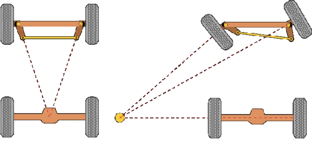
For two wheel steering, an Ackermann steering geometry accounts for the different turning radius of each wheel. The basis of the geometry is shown in Figure 3.
Figure 2-4: Diagram of Ackermann steering geometry.
I used my CAD model in Solidworks to simulate the steering. By adjusting the angle to the back wheel and changing the distance between the front wheels, I was able to set up the Ackermann geometry precisely and get an approximation of how the steering would work. I could then use the dimensions from the CAD model when fabricating the parts.
Once assembled, I found that there were several problems with the steering. At first, the steering worked smoothly because it was unloaded. However, once the go-kart was loaded with my weight, the flange bearing holding the steering wheel shaft in place began shifting because it had an adjustable housing. To correct this, I made a large bushing to be mounted to the bottom of the go-kart to help support the steering shaft. I bored out a round of delrin, which is a soft, low friction plastic, to fit over the steering shaft and also cut an angle into the profile so that it would press flush against the bottom of the main platform. I then counterbored holes in a mounting plate and bolted the plate to the angled face. Once flush, I drilled and tapped holes into the main platform to secure the bushing.
Another problem was that the ball joints I had for the steering linkage were hitting their
maximum angle before the wheels could turn enough for a decent turning radius. Even switching to high strength ball joints with a larger allowed angle wasn't enough. To fit this, I shortened the spacer seen in Figure 2-5. This adjusted the angle of the ball joints favorably, allowing them to rotate further.
13
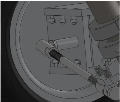
Figure 2-5: Picture of steering block and tie rod connection
The last problem was that when the wheel was turned too far, one wheel would start retracting. This is a problem of my particular steering configuration, which directly connects the steering column to the wheels, allowing for only a small maximum rotation of the steering wheel. To correct this I made a new, longer connector that resulted in a higher horizontal displacement for the same rotation. This reduced the turning precision slightly, but allowed for a larger turning radius.
2.3 Drivetrain
The drivetrain is a fundamental engineering problem for all vehicles. The drivetrain consists of the motor, transmission, and any drive wheels. Drivetrain components need to be mounted robustly and operate efficiently to be safe and effective. For Eli-Kart, I designed the frame so that a motor could be easily mounted to the steel tubing. For the brushless hobby aircraft motor I had, it would only take a single mounting plate to secure. After directly bolting a ¼” plate of aluminum to the frame, I drilled mounting holes that matched with the motor, and milled slots into the plate to allow for proper tensioning of the drive belt.
14
Figure 2-6: Picture of motor mount with a brushless hobby aircraft motor.
For simplicity and ease of operation, there would only be one gear. I decided to use a 15-5 HTD belt to transmit power from the motor shaft to the drive wheel. I chose belts because they are slightly more efficient and quieter than their main competitor in small electric vehicles, chains. I wanted a maximum speed of around 20mph (or 9 m/s), so I calculated the gear ratio I needed to hit this speed while maximizing torque using the equation below.
(1)
I calculated that I needed a gear ratio of almost 12 for a 10,000 rpm motor. Given that the wheels I used already had a 72-tooth pulley built into the hub, this would mean using only a 6 tooth pulley. However, the smallest pulley that I could find had 12-teeth, which doubled my top speed at the cost of cutting torque at the wheel in half.
15
3. Custom Motor
3.1 Design constraints and calculations
Several equations govern the properties of an electric motor. The most important variable in these equations is the motor constant, k. The motor constant is made up of a combination of stator size, windings, and magnetic field. I had to keep these in mind when choosing the components for my motor to make sure it would perform well. Torque (τ) and rotational velocity (ω) of a motor are both related to k.
(2)
(3)
(4)
N is the number of turns of wire on each tooth of the stator, B is the remnant flux from the magnets, L is the length or thickness of the stator, and D is the diameter of the stator. k is also related to speed by (3) and torque by (4), where V is the voltage and i is the current through the windings. As much as I could, I wanted to maximize these values.
When choosing components for my motor, the first priority was cost. The most expensive part of a custom motor can easily be the stator. A stator is made up of numerous laminations of steel. These laminations have the same cross-sectional shape and are stacked to create the desired thickness. To reduce cost, I searched on the Internet to get a low price. Luckily, I found four matching stators that were intended to be used for the alternator in a motorcycle. By combining these stators into one, it would give me a relatively large motor for powering a small vehicle.
Magnets are also an important (and often expensive) part of each motor. The stronger the magnets are, the more powerful the motor generally is. Magnet strength is related to the motor constant, with strong magnets resulting in a high Br for Eq. (1). Because of the size of my motor, I was limited in
my selection without opting for custom sized magnets. Since my stators had 18 teeth, I needed an even number of magnets that couldn’t be 18 because the magnetic field would then prevent the motor from rotating. After some calculations, I found that I could fit 16 magnets that were ¾” wide and ¼” thick around my stator with minimal space between them.
After cost, I initially wanted to design the motor around my motor controller. The Kelly Controller KBS line, which is suitable for small electric vehicles, only allows for up to 70,000 ERPM
16
with the high speed option. ERPM is the mechanical RPM of the motor multiplied by the number of magnet pole pairs. Given that my stator had 18 teeth, the motor would probably have 8 or 10 magnet pairs, limiting the maximum RPM to well below 10,000 even at high voltages. By using equations (2) and (3) and finding the torque through finite element analysis, I could reverse engineer the motor’s speed, making sure that it would be below the controller limit.
Once the stator, magnets, and can were finalized I could measure the parts and sketch a 2D profile in CAD.
Figure 3-1: CAD sketch showing the outer edge of the motor’s profile.
Once I had the profile, I could see how turns of wire I could fit between each tooth. I knew that I would need a lot of wire for such a big motor, so I decided to base my calculations of 18AWG magnet wire, which is just over 1mm in diameter, making it relatively thick. By close-packing the wire, I found that I could fit about 68 turns around each tooth.
17
Figure 3-2: CAD sketch showing ideal close packing of wire around a stator tooth. However, while unwinding the motor there were only 42 turns of 18AWG wire, which allowed for no bunching toward the tip. After performing a test wind, I found that I could fit __ turns of 18AWG wire easily. I also wanted to able to run my motor continuously at high current. 18AWG wire can sustain about 16 amps, so to make sure it would be safe to operate at the 120A maximum of my motor controller I decided to use 10 wires in parallel to achieve an ampactity of 160A. This would allow for around 5 turns of 10 wires in parallel without cramping the windings too much.
Finite Element Method Magnetics is an FEA program that allow you simulate the performance of an electric motor. By importing a file of the motor cross section into the program and assigning each block material and magnetic properties, the program can provide a variety of information about the operating conditions. Figure (2) shows a graphic representation of the magnetic flux.
18
FEMM calculated a torque of 21.96 at 100A, yielding a motor constant k of .11 . By equation (5), I found that RPM/volt of the motor would be 43.5, yielding 1740 maximum RPM at 40V. With 16 magnet pole pairs, this would be well below the 8750RPM limit of the controller.
3.2 Mechanics and Fabrication
Once the electrical side of the motor was figured out, I had to design the mechanical side. I decided to work on the stators first and progress outward. The stators I chose for the motor came pre-wound with magnet wire, ready to be used in a motorcycle. Because I wanted to have my own wire configuration and also combine the stators, I had to unwind each of them. The epoxy used to hold the windings together was tough, so it took a pair of pliers and a good deal of time to unwind them. A heat gun was used to soften the bonds when the wires got stuck and began to break.
To combine the stators into one unit, I designed a part for the stators to slide over. I then bored a hole in this stator assembly with a lathe so that I could press fit bearings into it for rotating around the central shaft. I then designed an end plate to attach the stators to the central hub, holding everything together. This would hold everything together.
Figure 3-4: Picture of stator assembly.
To hold the stator assembly in place, I used the pre-drilled holes in the laminations to attach them to the outside mounting face. The holes for the bolts that would go all the way through the stators would be counterbored, while mounting holes would be drilled and tapped. Because this would be a very structural component, I used a thick round of aluminum alloy. In the center of the face would be a shaft bearing to help support the torque from the pulley on the end. A large bearing was pressed over the outside edge of the aluminum face to isolate it from the spinning can.
19
I made the can out of 1/8” thick steel to contain the magnetic field from the magnets. . I sized the inner diameter of the can to create about a 1mm gap between the stator and the magnets. After a lot of turning on a lathe, I used a jig that was 3D printed to position the magnets properly. Once tacked in place with superglue, I mixed a viscous epoxy to fill the gaps between the magnets.
Figure 3-5: Picture of all the magnets in position with epoxy filling the gaps.
I decided to use a thick piece of clear polycarbonate to fill the gap between the large bearing and the steel can, tapping radial holes in the polycarbonate to attach it to the can. For the other endcap, I also wanted to use polycarbonate to allow for a clear view of the stator assembly. To attach the drive shaft to the can of the outrunner, I welded a plate of steel to one end of the shaft. I then drilled holes through the plate so that it could be mounted to the polycarbonate. I also cut out an area in the polycarbonate to recess the mounting plate. After turning down the weld bead, I put the pieces together and drilled and tapped the polycarbonate, ensuring that they could transmit the necessary torque.
20
I decided to use a dLRK winding style. This is the most effective winding style for the type of stator I had, providing slightly higher efficiency than the LRK style. The terminology used for dLRK winding follows the style of “AabBCca…” The letters A, B, and C indicate the motor phase while the upper case letters indicate the turning direction (either clockwise or counter-clockwise). For my stator, which has 18 teeth, I used AabBCcaABbcCAabBCc.
After winding each phase with one strand of 18AWG magnet wire, I ran out of time and had to stop working on the motor. I had also had either machined the inner diameter of the can slightly too small or misaligned the stator slightly because the stator was rubbing against the can. This made it very
difficult to spin by hand, and might damage the motor if I tested it electronically. I will likely try to fix this issue by reseating the stator inside the can bearing and/or sanding down the stator until it spins smoothly.
However, to finish the motor, I would have had to insert hall-effect sensors so that I could control the motor with a sensored controller. Sensored control uses the hall-effect sensors to determine the position of the rotor through the magnetic field, and applies current based on the feedback. The other method of control is called “sensorless” which used the back EMF of the motor to control its speed. However, this makes it difficult for the motor to start up from a stand-still, causing potentially harmful current spikes.
To insert the sensors in the correct sensing position, I would need to insert the sensors 120 electrical degrees apart to match the settings for my Kelly controller. To calculate this, you first need to figure out how many electrical degrees are between each tooth. The formula for this is
⁄ (5)
For my motor, each tooth came out to be 160 electrical degrees apart. Since you can’t actually place a sensor a fraction of a tooth away, you need to position the sensors such there is separation 120° ± 360° for each sensor. For me motor, this meant placing them in the slots between the teeth with 3 slots between each sensor.
21
4. Predictions and Conclusions
4.1 Efficiency
Since the motor wasn’t able to be finished in time, I wasn’t able to perform all of the tests I wanted on Eli-Kart. However, I could still predict the efficiency, or energy consumption. Efficiency is important for saving energy and extending the run-time of the go-kart. For my purposes, I wanted to find out how long the battery should last. Many different factors influence efficiency, from the drivetrain to the controller to the wiring. While no amount of calculations is as good as a real world test, I decided to predict how much energy would be used while driving at 20mph.
First I calculated the rolling resistance, or how force is resisting the direction of travel due to the wheels rubbing against the ground. The equation for this force is as follows.
(6)
Crr is the coefficient of rolling friction and N is the normal force based on the loaded weight of the
vehicle. A Crr of 0.005 is a conservative estimate for bicycle tires, so I thought that would be a good
starting place for my 8” pneumatic tires. Given that the kart weighs about 93 pounds, with a loaded weight of 250lbs with a driver, the normal force N would be 1111 Newtons. The resulting force according to (6) came out to be 5.55N.
Aerodynamic drag is another big area where energy is lost. I created a test dummy in Solidiworks and ran a simulation to find how much force was applied by the 20mph wind. The simulation calculated that the horizontal force from the airflow averaged 11.3N
22
To go with the rolling resistance and drag forces, the motor and controller and drivetrain have their respective losses. Brushless motors are very efficient, and with proper alignment of sensors, the controller should be very efficient too. Since the transmission only involved one belt, there would also be minor losses there. There are also resistive losses and any other extraneous inefficiencies, which may or may not be negligible, but my conservative estimates should provide a close approximation.
To come up with a value in watts needed to be output by the motor, I needed to convert the resistive forces into a unit of power. All that was required to do this was multiply the total force by the velocity of the go kart. The total equation for energy loss I used is below.
( ) (7)
To recap (7), is the force from the rolling resistance, is the force from the aerodynamic drag, and is the velocity of the go-kart in m/s. is the efficiency of the motor while is the efficiency of the controller, both of which I assumed to be 90%. is the efficiency of the drivetrain, which I assumed to be 95%. The energy required to operate at 20mph was calculated to be 175 watts, which is reasonable for a smooth, flat surface.
4.2 Conclusions
Through this project, I’ve found that personal electric vehicles are very comprehensive projects. When completed, they can be very fun and even practical if used for transportation. However, building a motor took much more time and effort than I initially expected. For use in an open space under a go-kart such as Eli-kart, a commercial motor would be much easier and potentially cheaper. Only for truly specific purposes can a custom motor be well justified. Still, designing and building Eli-Kart was a great learning experience that will remain a memorable part of my time at MIT.
23
5. Bibliography
Make Your Own Miniature Electric Hub Motor. (n.d.). Retrieved May 21, 2012, from Instructables: http://www.instructables.com/id/Make-Your-Own-Miniature-Electric-Hub-Motor/
Mevey, J. R. (2009). SENSORLESS FIELD ORIENTED CONTROL OF BRUSHLESS PERMANENT MAGNET SYNCHRONOUS MOTORS. Manhattan, Kansas, United States of America.
Ackermann steering geometry. (n.d.). Retrieved May 21, 2012, from Wikipedia: http://en.wikipedia.org/wiki/Ackermann_steering_geometry