Design of Mechanical Arterial Simulator
by
Lauren Chai
Submitted to the
Department of Mechanical Engineering
in Partial Fulfillment of the Requirements for the Degree of Bachelor of Science in Mechanical Engineering
at the
Massachusetts Institute of Technology
June 2012
ARCHIVES
MASSACHUSETTS INSTFTUTE OF TECHNOLOGYJUN
28 2012
LIBRARIES
© 2012 Massachusetts Institute of Technology. All rights reserved.
Signature of Author:
Department of Mechanical Engineering
June 1, 2012 I i ,'~ Certified by: Accepted by: Dr. Brian Anthony Research Scientist, LMP John H. Lienhard V Samuel C. Collins Professor of Mechanical Engineering
Undergraduate Officer
F 1
Design of Mechanical Arterial Simulator
by
Lauren Amy Chai
Submitted to the Department of Mechanical Engineering
on May 31, 2012 in Partial Fulfillment of the
Requirements for the Degree of
Bachelor of Science in Mechanical Engineering
ABSTRACT
A force controlled ultrasound probe is being explored as a new method of measuring blood
pressure. An arterial simulator was designed and built for experiments. For this simulator, the
vessels and bulk material were designed to meet the specifications of literature values of the
physical dimensions and elastic modulus of carotid and brachial arteries and bulk surrounding
the arteries. This was done through the use of a PVA cyrogel and Thermo rubber- mineral oil
solution as the materials for the vessel and bulk material respectively. The concentration of the
ingredients and the number of freeze thaw cycle of the cyrogel control the elasticity of the two
materials. Custom molds were fabricated to the desired physical dimensions. Upon integration of
the vessel and bulk, the vessel was connected to a network of hoses and a pump. The pump is a
diaphragm pump whose volume/stroke and speed can be independently controlled to simulate the
pulsing of a real human heart. Measurements were taken of the force applied to the probe for
static pressures to demonstrate the force varying linearly with pressure. Further measurements
were taken with fluid flowing through the vessel at various probe heights to demonstrate how
force and thus pressure vary with height and to demonstrate that the probe can detect the
waveforms that result from the vessels pulsing with each stroke of the diaphragm pump.
Thesis Supervisor: Dr. Brian W. Anthony
Tile: Research Scientist, LMP
I would like to thank Brian Anthony for his support and feedback throughout this project as well as Matthew Gilbertson, Bill Vannah, Aaron Zakrzewski and Shih-Yu Sun for their feedback and collaboration.
Contents
Abstract 3 Acknowledgements 5 Contents 7 List of Figures 9 List of Tables 11 1 Introduction 13 1.1 B ackground . . . . 13 1.2 O utline . . . . 132 Arterial system: physical components and characteristics 15 3 Physical characteristics of the arteries and developement of working replica 17 3.1 Literature values: artery dimensions . . . . 17
3.2 Artery Material: Polyvinyl Alcohol Cyrogel . . . . 17
3.3 A rtery M olds . . . . 21
3.3.1 Version 1- Single Teflon tubes . . . . 21
3.3.2 Version 2- Clamshell Wax Blocks . . . . 22
3.4 Storage of Artery Replicas and Lifetime . . . . 23
4 Physical Characteristics of the bulk surrounding artery and develope-ment of working replica. 25 4.1 Bulk Dim ensions . . . . 25
4.2 B ulk M old . . . . 30
4.2.1 Version 1 - Single teflon tubes . . . . 30
4.2.2 Version 2 - Clamshell . . . . 30
4.2.3 Version 3 - Single piece . . . . 31
4.3 Integrating the artery and bulk replicas . . . . 36
4.4 Storage of Bulk Replica and Lifetime . . . . 37
5 Dynamic Model 40 5.1 Dynamic Properties and Theoretical Model . . . . 40
5.2 Building the Beating Heart . . . . 41
5.2.1 Selection of Pump . . . . 41
6 System performance 42 6.1 Static and Dynamic Results . . . . 42
7 Conclusion and future work 45
Appendix A Replica Materials Data Sheets 47
Appendix B Pump and Motor Datasheets 63
Appendix C Matlab functions 69
List of Figures
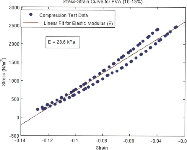
2.1 Structural Loop of probe pressing down on artery. The probe and bone are assumed infinitely stiff compared to the other components whose la-bels are described in Table 2.1. . . . . 15 3.1 Stress Strain Curve from Compression tests of PVA sample (10-15%
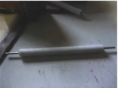
PVA). The two lines of blue dots represent two cycles of the compres-sion test in the instron testing machine. . . . . 20 3.2 Figure showing first version of Artery molds. The rod is held in place by
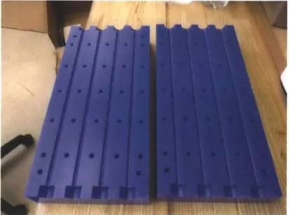
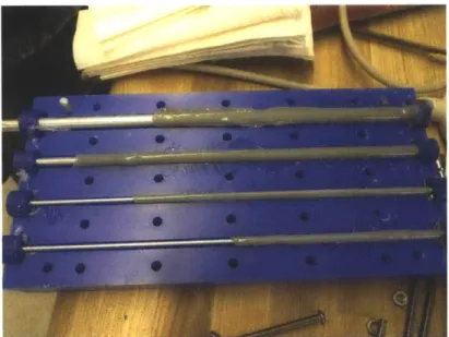
o-rings on the sides of the tube. . . . . 21 3.3 Picture of Wax Molds for Artery phantom. The diameter of the
cylindri-cal cutouts down the length determine the outer diameter of the vessel. Bolts clamp the two sides together and dowel pins maintain alignment. 22 3.4 Picture of top of closed Wax Molds for Artery phantom (the bottom is
identical) showing the wells. Caps fit into these wells to both hold a rod which sets the inner diameter of the vessel and to seal the wax blocks. . 23 3.5 Finished Arteries in Wax Molds. See Table 3.3 for dimensions. . . . . . 23 4.1 Sample of TPR Copolymer used in Compression Tests. . . . . 26 4.2 Stress Strain Curve for TPR Gelatin (4% Copolymer). The two lines
of blue dots represent two cycles of the compression test in the instron testing m achine. . . . . 28 4.3 Stress Strain Curve for TPR sample (5% Copolymer). The two lines
of blue dots represent two cycles of the compression test in the instron testing m achine. . . . . 29 4.4 First Mold for Bulk material. Caps on the end have holes for holding a
rod to create a negative for the artery in the bulk replica. . . . . 30 4.5 Results after first combination of vessel and artery. The bubbles are from
the vessel as it boiled away from the heat of the fluid bulk, leaving behind a brow n residue. . . . . 31 4.6 Figure showing Version 2 of bulk replica, 14 inches in length. The ruler,
showing scale, is 12 inches . . . . 32 4.7 Figure showing actual limits of edge effects. . . . . 32 4.8 Figure showing seam between halves of clamshell in ultrasound. The
series of lines in bottom half are reflections from the mold's aluminum base. The ultrasound image side borders are the limits of the probe, not
the replica. . . . . 33 4.9 Figure showing dimensions of replica version 3. The length was reduced
from 14 to 10 inches. The ruler, showing scale, is 12 inches. . . . . 34 4.10 Mold for bulk material. The side walls each have a hole to hold a rod
that forms the negative for the artery. . . . . 35 4.11 Figure showing successful integration of the bulk and cyrogel. . . . . 37
4.12 Ultrasound Cross section of simulator with no compression. . . . . 37
4.13 Ultrasound Cross section of simulator with compression. . . . . 38
4.14 Ultrasound Length view of simulator with no compression. . . . . 38
4.15 Ultrasound Length view of simulator with compression. . . . . 39
4.16 Ultrasound Length view of simulator with bubble injected to highlight artery walls. The artery size used is that of a brachial artery. A significant portion of the vessel is taken up by the blurring by the bubble. . . . . . 39
6.1 Figure showing Final Hardware Schematic of setup. . . . . 42
6.2 Flow Diagram of Hardware. . . . . 43
6.3 Figure showing results of static measurements. Force on Probe increases linearly with Pressure as expected. . . . . 44
6.4 Figure showing dynamic waveforms from beating artery. As probe height decreased, force measured increased. Also, less distinguishable are the waveforms of the force as the vessel pulsed. . . . . 44
List of Tables
2.1 Description of Labels in Structural Loop from Figure 2.1 . . . . 16
2.2 Simulator Components and Dependent Properties . . . . 16
3.1 Summary of materials and hardware for manufacturing PVA cyrogel . . 18 3.2 Process plan for manufacturing of PVA cyrogel . . . . 19
3.3 Version 2 mold vessel descriptions and dimensions . . . . 22
4.1 Summary of materials and hardware for manufacturing PVA cyrogel . 26
4.2 Process plan for manufacturing TPR copolymer-mineral oil solution . 27 4.4 Bulk Replica Dimensions . . . . 30 4.5 Bulk M old Dimensions . . . . 31
4.6 Table describing how to insert vessel into bulk replica . . . . 36
5.1 Maximum and minimum pressures from blood pressure waveform [12] and calculated resistances. . . . . 40
6.1 Results and Images from Static Tests at constant displacement. As Fluid Pressue increases, so does the vessel perimeter and force on probe. . . . 43
Chapter 1
Introduction
1.1
Background
The standard for measuring blood pressure is the use of a sphygmomanometer whose cuff exerts pressure onto the brachial artery. The cuff wraps around the upper arm and inflates until blood flow is completely cut off. Then, the cuff is deflated until blood begins to flow again (systolic pressure) and further until the artery once again pulsates (diastolic). For the average healthy adult, cutting off the blood flow like this is at most mildly unpleasant. For those with much weaker blood pressure, such as elderly and post-operative patients, the cutting off of blood flow is extremely uncomfortable and can lead to bruising and disturbing sleep.
A force-controlled ultrasound probe [13] is being explored as an alternative way to measure blood pressure, its main features being that it does not require blood to be completely stopped. The theory behind this method is that if one can measure the force needed to compress an artery and see via ultrasound how the artery responds to an external force, one should be able to derive the internal blood pressure from the resistance of the artery to the external force assuming the other physical properties can be derived or measured somehow (e.g. the elasticity of the artery wall and surrounding tissue).
Various components of this method have already been developed by The Computa-tional Instrumentation Lab -a force controlled probe developed by Matthew Gilbertson [13] will be used to measure the force exerted by the probe, and elastography numerical models are being developed by Aaron Zakrzewski. For this thesis, we develop a physical model in which all the physical properties can be known/controlled in order to confirm the elastography models. This was done by first examining the static and dynamic fac-tors of the arterial blood waveform, or the facfac-tors that contribute to the internal fluid pressure of the artery and how that waveform looks over time. Then each component was designed and manufactured to make a static model before a pump was introduced to
make a complete pulsating artery that could be used to develop and validate a method to measure blood pressure.
1.2
Outline
This report is has been divided into six chapters
" Chapter 1: Arterial system: physical components and characteristics
" Chapter 2: Physical characteristics of the arteries and development of working replica.
" Chapter 3: Physical characteristics of the bulk surrounding artery and develope-ment of working replica.
" Chapter 4: Dynamic model schematic and pump selection. * Chapter 5: System performance
Chapter
2
Arterial system: physical
components and characteristics
The system components were determined by looking at the structural loop in a cross section of the arm during a blood pressure measurement (Figure 2.1). The probe and bone are approximated as infinitely stiff while the bulk, artery wall and blood have some associated finite stiffness.
Muscle and fat K1
Bone
Figure 2.1: Structural Loop of probe pressing down on artery. The probe and bone are assumed infinitely stiff compared to the other components whose labels are described in Table 2.1.
From Figure 2.1, one can see that between the probe and bone, if one knows the physical characteristics of the bulk (muscle and fat) and the arterial wall, one may be able to estimate the blood pressure from the force measured by the probe and estimate the strain of the arterial walls. The components of the system, as well as the properties being controlled have been summarized Table 2.2.
TABLE 2.1: Description of Labels in Structural Loop from Figure 2.1
Label Component(s)
Ki Bulk Elasticity
K2 Artery Replica Elasticity
K3 Elasticity Associated with Blood Pressue
TABLE 2.2: Simulator Components and Dependent Properties
Body Part Component(s) Dependent Physical Properties
Muscle, fat Bulk Replica bulk elasticity, vessel depth
Artery Artery Replica Vessel outer diameter, wall thickness Blood internal pressure fluid resistances of piping, fluid flow
Chapter 3
Physical characteristics of the
arteries and developement of
working replica
3.1
Literature values: artery dimensions
The human body varies widely from individual to individual and so likewise the physical the dimensions of the vessels such as the elasticity, thickness and diameter also vary. Actually, these properties are also telling of the health of the individual. Elasticity decreases with age. Significant health problems may result from the internal diameter of the vessel being reduced to the point of no blood flow by plaque and decreasing elasticity. Many studies have been conducted into how these values vary among the population to produce the following values:
" vessel elasticity: 70-100kPa[6]
" wall thickness: approx 0.2-0.4 mm (brachial) [4] and approx 0.65-0.95mm(Carotid) [8] " artery diameter: 4.1 to 4.3 mm (± 0.6 mm)[4]for brachial arteries; 6-8 mm ([9])
for carotid arteries.
For the artery replica, the goal is to be able to consistently fabricate these dimensions and control variations.
3.2
Artery Material: Polyvinyl Alcohol Cyrogel
In order to control these dimensions, Polyvinyl Alcohol Cyrogel (developed by Hoskins, et al[1], Poepping et al[2] and King et al[6]) has been chosen as the material for the vessels. It is a solution that can be cast around a negative mold before being frozen. Once defrosted, the cyrogel is compliant but solid. Thus, I can control the vessel diameter and wall thickness. The elasticity is controlled by the concentration of PVA and the number of times the PVA is frozen. The process plan is described in Table 3.2. A complete list of hardware and materials in Table 3.1. Each batch (using the version 2 molds) consists of the vessels from the final wax molds (which yields 4 vessels of dimensions described in Table 3.3 ) and a sample for compression tests (5cm height, 5 cm diameter). For one complete batch at 10% PVA, one needs 725 ml distilled water and 80.5 g PVA.
It is very important after mixing that the bubbles be allowed to rise out completely. For our tests, we require a 6 inch vessel segment in which there are no bubbles (which
TABLE 3.1: Summary of materials and hardware for manufacturing PVA cyrogel Category Components Hardware " Hot Plate * Freezer " 1 L Glass Beaker * Plastic food wrap
* pot (large enough to hold 1 L beaker)
* stirrer
" water (water bath) " freezer
Materials
* Polyvinyl Alcohol (see Ap-pendix for MSDS)
" Graphite powder " distilled water
create holes that leak). The elasticity of the cyrogel is varied by the number of freeze thaw cycles. Three freeze-thaw cycles are enough to get within the expected range of elasticity of 24-135 kPa (by King et al [6]), with more freeze cycles expected to increase the stiffness. A sample (5 cm diameter, 5 cm height) was made at 10% PVA and three freeze cycles and subjected in compression tests to produce a Young's Modulus of 23.6 kPa (See Figure 3.1).
TABLE 3.2: Process plan for manufacturing of PVA cyrogel
Process Material [Measurement Notes
Mix PVA in dis- Polyvinyl PVA is 10-15% of Do not turn on the heat until
tilled water Alcohol, the total weight of there is an constant, clump-distilled the solution free suspension.
water, beaker
Cover beaker con- plastic food Temperture of Hot plate is on medium-low. taining solution wrap, wa- water bath is at The plastic food wrap is used with plastic wrap ter bath about 70-80 C to reduce the evaporation of and place in a (hot plate, the water. Mix every minute water bath. Turn pot, water, to break up clumps. PVA is on heat stirrer, fully dissolved when mixture thermome- has the consistency of honey ter) and there are no clumps Tun off heat. Add carbon Carbon is 1% of N/A
carbon to the so- graphite final weight. lution.
Leave the solution N/A Cool to room Cooling takes anywhere from to cool to room temperature 2 - 6 hours. It is very im-temperature and (about 21 C) portant that the solution is al-bubbles to rise lowed to cool as this will af-out. fect how evenly the PVA will freeze and the true freeze time of the PVA solution.
Pour into molds Plastic food N/A Settling time is dependent on and allow bubbles wrap many factors such as the vis-to rise out before cosity of the solution and how freezing. Keep much resistance there is in the molds upright molds to the bubbles rising throughout entire out. An accurate number is process. Cover dependent on the mold. For mold bottom the wax molds used, this pro-with plastic food cess takes about 20 minutes wrap. and PVA solution needs to be constantly added. The wax blocks have wells to make this process easier.
Freeze and defrost Freezer Freeze time is 12 N/A
as needed. hours and defrost time is 12 hours
Open mold and N/A N/A N/A
slide vessels care-fully off rods.
Stress-Strain Curve for PVA (10-15%)
500
0
-500
-0.14
-0.12
Figure 3.1: Stress Strain Curve from The two lines of blue dots represent testing machine.
-0.1
-0.06
-0.06
-0.04
Strain
Compression tests of PVA sample (10-15% PVA). two cycles of the compression test in the instron
3000
2500
2000
1500
1000
P11z
UO-0.02
3.3
Artery Molds
3.3.1 Version 1- Single Teflon tubes
The first molds were teflon pipes of 6 inches in length in which a metal rod was suspended and sealed by two O-rings (Figure 3.2). Teflon was chosen as the material for the mold for its low friction. It was sufficient as a first pass at manufacturing the vessels, but had some design flaws:
" Single teflon tubes were cumbersome to maintain upright during settling process. " Required constant supervision and use of syringe to fill tube as bubbles rose out
and solution leaked out.
" Vessels had to be pulled out lengthwise from mold, resulting in them sometimes tearing if one was not careful.
* Since the molds had to be laid on their sides during freezing, the vessels had noticeable variation in wall thickness along length
Figure 3.2: Figure showing first version of Artery molds. The rod is held in place by o-rings on the sides of the tube.
3.3.2 Version 2- Clamshell Wax Blocks
The second molds were larger blocks made of machinable wax. Two halves are machined and held together by bolts. Its features include longer vessels, clam shell design for easy removal, wells at the top and steady base for standing upright to aid both settling and freezing. Additionally, the blocks have the ability to cast multiple vessels at the same time, with inner diameter and wall thickness easily varied by the inner tube diameter and dimensions of well caps. Figures 3.3 and 3.4 show the inside of the mold and the wells top of the closed mold.
Figure 3.3: Picture of Wax Molds for Artery phantom. The diameter of the cylindrical cutouts down the length determine the outer diameter of the vessel. Bolts clamp the two sides together and dowel pins maintain alignment.
Since these molds use hard caps instead of o-rings, they have a problem of leaking at the bottom. For this reason, the wax blocks were made to be extra long (10 inches) resulting in vessels that are consistently over 6 inches in length (range has been from 6-8 inches). The bottom of the wax block also needed to be wrapped with plastic food wrap for easier clean up.
Figure 3.5 shows a typical set of vessels from these blocks.
TABLE 3.3: Version 2 mold vessel descriptions and dimensions
Vessel Replica of Outer Diameter Inner Diameter
(Wall Thickness)
A Brachial Artery 0.25" 1/8" (1/8")
B Brachial Artery 15/64" 1/8" (7/64")
C Carotid Artery 3/8 " (1/8")
Figure 3.4: Picture of top of closed Wax Molds for Artery phantom (the bottom is identical) showing the wells. Caps fit into these wells to both hold a rod which sets the inner diameter of the vessel and to seal the wax blocks.
Figure 3.5: Finished Arteries in Wax Molds. See Table 3.3 for dimensions.
3.4
Storage of Artery Replicas and Lifetime
Storing the arteries has two goals: reduce the growth of fungus in the water based so-lution, and preventing dessication. The artery replicas were first stored in wet paper towels but the paper towels themselves also quickly dried out. Storing the arteries in water risked them absorbing more of the water and losing knowledge of their physical properties. The solution was to store the arteries in the same mineral oil used in manu-facturing of the bulk replicas, preventing dessication and inhibiting the growth of mold. Any residue oil on the artery does not impact the full assembly since the artery will be surrounded by the same mineral oil in the bulk material. Nevertheless, the lifetime of
Chapter 4
Physical Characteristics of the
bulk surrounding artery and
developement of working replica.
4.1
Bulk Dimensions
To simulate muscle and fat, the bulk replica should have an elasticity of 3-6kPa[7] and vessel depth of 0.5 to 2cm as determined from ultrasound scans. Thus the material chosen was a solution of mineral oil and Kraton thermoformed rubber copolymer (TPR)
(5% of the mineral oil weight) developed by Oudry et al[3]. The method is described
in Table 4.2 and a complete list of materials and hardware is described in Table 4.1. Amount of bulk material for a particular mold was determined by calculating the volume of the mold and using the matlab program GramTPR.m (see Appendix 3) to compute the weight of TPR copolymer needed. The input is the volume of bulk needed (also the volume of the mineral oil used). The output is the grams of TPR copolymer needed for 5% of the weight of mineral oil.
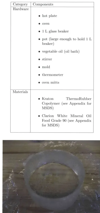
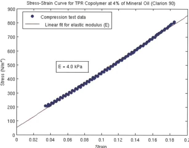
Compression tests of a sample (5 cm diameter, 5 cm height as seen in Figure 4.1) show the expected young's modulus of 4.99 and 5.25 kPa for 4 and 5 % copolymer in oil respectively. See Figures 4.2 and 4.3.
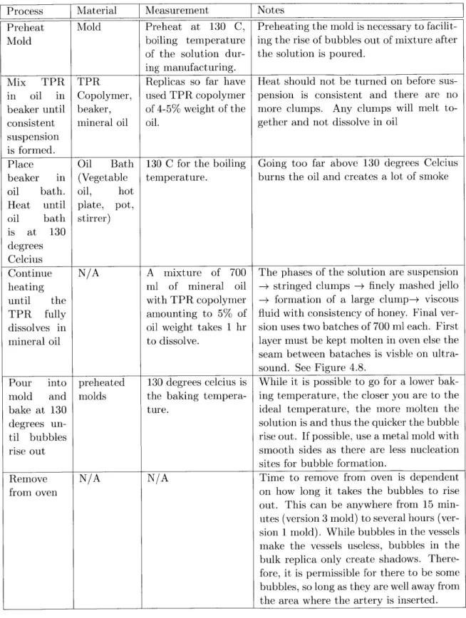
TABLE 4.1: Summary of materials and hardware for manufacturing PVA cyrogel Category Components Hardware " hot plate " oven " 1 L glass beaker
* pot (large enough to hold 1 L beaker)
* vegetable oil (oil bath) " stirrer " mold " thermometer " oven mitts Materials " Kraton ThermoRubber
Copolymer (see Appendix for MSDS)
" Clarion White Mineral Oil Food Grade 90 (see Appendix for MSDS)
TABLE 4.2: Process plan for manufacturing TPR copolymer-mineral oil solution
Process |Material Measurement
jNotes
Preheat Mold Preheat at 130 C, Preheating the mold is necessary to
facilit-Mold boiling temperature ing the rise of bubbles out of mixture after
of the solution dur- the solution is poured.
ing manufacturing.
Mix TPR TPR Replicas so far have Heat should not be turned on before sus-in oil in Copolymer, used TPR copolymer pension is consistent and there are no beaker until beaker, of 4-5% weight of the more clumps. Any clumps will melt
to-consistent mineral oil oil. gether and not dissolve in oil
suspension is formed.
Place Oil Bath 130 C for the boiling Going too far above 130 degrees Celcius beaker in (Vegetable temperature. burns the oil and creates a lot of smoke
oil bath. oil, hot
Heat until plate, pot,
oil bath stirrer)
is at 130 degrees Celcius
Continue N/A A mixture of 700 The phases of the solution are suspension
heating ml of mineral oil - stringed clumps - finely mashed jello
until the with TPR copolymer - formation of a large clump-+ viscous
TPR fully amounting to 5% of fluid with consistency of honey. Final
ver-dissolves in oil weight takes 1 hr sion uses two batches of 700 ml each. First
mineral oil to dissolve. layer must be kept molten in oven else the
seam between bataches is visble on ultra-sound. See Figure 4.8.
Pour into preheated 130 degrees celcius is While it is possible to go for a lower bak-mold and molds the baking tempera- ing temperature, the closer you are to the
bake at 130 ture. ideal temperature, the more molten the
degrees un- solution is and thus the quicker the bubble
til bubbles rise out. If possible, use a metal mold with
rise out smooth sides as there are less nucleation
sites for bubble formation.
Remove N/A N/A Time to remove from oven is dependent
from oven on how long it takes the bubbles to rise
out. This can be anywhere from 15 min-utes (version 3 mold) to several hours (ver-sion 1 mold). While bubbles in the vessels make the vessels useless, bubbles in the bulk replica only create shadows. There-fore, it is permissible for there to be some bubbles, so long as they are well away from the area where the artery is inserted.
Stress-Strain Curve for TPR Copolymer at 4% of Mineral Oil (Clarion 90)
900
Compression test data
600 - Linear fit for elastic modulus (E
700 -600 -E 500
4.0
kPa
z to c 400 300 200 100 0 0 0.02 0.04 0.06 0.06 0.1 Strain 0.12 0.14 0.16 0.16 0.2Figure 4.2: Stress Strain Curve for TPR Gelatin (4% Copolymer). The two lines of blue dots represent two cycles of the compression test in the instron testing machine.
Stress-Strain Curve for TPR Copolymer at 5% of Mineral Oil (Clarion 90)
1600
* Compression Test Data
1600 - __
Linear fir For Elastic Modulus (E)
1400 1200 -1000 Z" E =5.25:kPa] %
600
-a) W5 600 - 400-200 0 -200 -0.05 0 0.05 0.1 0.15 0.2 0.25 0.3 StrainFigure 4.3: Stress Strain Curve for TPR sample (5% Copolymer). The two lines of blue dots represent two cycles of the compression test in the instron testing machine.
4.2
Bulk Mold
4.2.1 Version 1 - Single teflon tubes
The first version of the mold had dimensions of 1-3/4" diameter, and 7 " as described in Table 4.4.
TABLE 4.4: Bulk Replica Dimensions Bone to Skin
Dis-tance 2" ± 0.5 1-3/4" + 0.1', upper Length 6.5 " t 1,, 6-3/4 + 0.1',
Figure 4.4: First Mold for Bulk material. Caps on the end have holes for holding a rod to create a negative for the artery in the bulk replica.
In this mold, the bulk material was to be cast around the vessel. However, the high temperature of fluid TPR mixture (about 130 degress Celcius) boiled away the cyrogel as seen in Figure 4.5.
4.2.2 Version 2 - Clamshell
The next version was to cast the bulk separately in a clam shell design. The mold is a much larger version of that in version 3 (See Figure 4.10). The dimensions of this version changed from a round cylinder to that of a block. The dimensions were chosen to initially isolate the vessel from any edge effects via Saint Venant's Principle, and leave room for selectively adding other features such as bone.
Tests revealed two important observations. Tests with a probe showed that the dimensions of version 2 were unnecessarily large due to how compliant the bulk material was (See Figure 4.7) . The second important observation was that the seam between
L
F
MeasuredReplica
+
Figure 4.5: Results after first combination of vessel and artery. The bubbles are from the vessel as it boiled away from the heat of the fluid bulk, leaving behind a brown residue.
Characteristic Dimension Desired Result Mold Dimension
Height (each half) artery dimension = 0.25" 5 times greater than 1.5" t 0.1
artery diameter to
negate effect of bone.
Length Probe width - 2" 3 times larger than 14" ±
probe dimension
in both directions
(6+6+2=14")
Width Probe thickness = 0.5" 3 times larger than 5-3/4 ± 0.1
probe dimension in
both directions with 2-1/4" space to move
probe along vessel
length"
TABLE 4.5: Bulk Mold Dimensions
4.2.3 Version 3 - Single piece
This version was now a single piece and reduced in size to a length of 10 inches (from 14 inches) in order to fit the mold into the conventional toaster oven used to bake the mold and so that less of the bulk material needed to be made per mold. Various ideas were also developed to address the problem of inserting the vessel into the bulk. One idea was to leave the hollow vessel cylinder in mold (used to make space for vessel), and string vessel through the much stiffer cylinder, before removing the cylinder. However, in the course of trying this, it was discovered that the bulk material was both elastic and robust enough such that the bulk could be stretched enough to allow the vessel to be pushed through by hand. The mold can be seen in Figure 4.10. Volume of material needed is about 1400 ml. This can be done in two batches so long as the first layer
Figure 4.6: Figure showing Version 2 of bulk replica, 14 inches in length. The ruler, showing scale, is 12 inches.
Figure 4.7: Figure showing actual limits of edge effects.
is kept molten in the oven, otherwise the seam between layers is visible on ultrasound. Typical dissolve time for 700 ml is about 1 hr and it takes about 10-15 minutes for
Figure 4.8: Figure showing seam between halves of clamshell in ultrasound. The series of lines in bottom half are reflections from the mold's aluminum base. The ultrasound image side borders are the limits of the probe, not the replica.
Figure 4.9: Figure showing dimensions of replica version 3. The length was reduced from 14 to 10 inches. The ruler, showing scale, is 12 inches.
Figure 4.10: Mold for bulk material. The side walls each have a hole to hold a rod that forms the negative for the artery.
4.3
Integrating the artery and bulk replicas
Table 4.6 describes how to integrate the artery replica and the bulk replica.
TABLE 4.6: Table describing how to insert vessel into bulk replica
Step Description Image
Step 1 One End of cavity in bulk Replica is stretch and ves-sel gently pushed through.
Step 2 Hand reaches
through to other
side to both
stretch middle
and guid vessel to other end of
cavity.
Figure 4.11 shows the integrated arterial simulator.
The ends of the vessel are attached to two hose fittings (clamped on by rubber rings made from long party balloons) and the vessel and hose were filled with water. Fig-ures 4.12, 4.13, 4.14 and 4.15 show ultrasound images of cross-sectional and lengthwise views of the vessel. Figure 4.16 shows an image with a bubble inserted to highlight the artery walls. These figures are for the simulated briachial artery.
The blurring at the edges of the arterial walls in Figure 4.16 are about 10-20% of the inner diameter. It is unclear if they are shadows or features. Due to how proportionally large they are to the artery diameter, the decision was made to move from examination of the brachial artery to the carotid artery in which these shadows will have a much smaller impact.
As discussed earlier, the TPR bulk replica is extrelely durable. However, the vessels are easily torn. Because of this, a lot of care must be taken when clamping the vessels onto the hose fittings. External forces that might jolt the hose fittings risk tearing the vessels risk tearing the vessel. To mitigate this (beyond careful set up), the vessel is cut slightly shorter (about 1 inch) than the width of the bulk replica so that the ends of the bulk hold the hose fittings in place. This becomes more important later during actual measurements since the orientation of the hose fittings, if extreme enough, will influence
Figure 4.11: Figure showing successful integration of the bulk and cyrogel.
Figure 4.12: Ultrasound Cross section of simulator with no compression.
4.4
Storage of Bulk Replica and Lifetime
The storage lifetime of the bulk replicas, according to Oudry et al[3], is at least 14 months with little change in overall physical properties. There is some minimal change
Figure 4.13: Ultrasound Cross section of simulator with compression.
Figure 4.14: Ultrasound Length view of simulator with no compression.
in elastic modulus, but this might be attributed to the issue of absorbed from the TPR-mineral oil solids. For this reason, the stored wraped in plastic food wrap. They can be then left on an extremely robust and difficult to tear.
mineral oil is easily bulk replicas are all open air shelf, being
Figure 4.15: Ultrasound Length view of simulator with compression.
Figure 4.16: Ultrasound Length view of simulator with bubble injected to highlight artery walls. The artery size used is that of a brachial artery. A significant portion of the vessel is taken up by the blurring by the bubble.
Chapter 5
Dynamic Model
5.1
Dynamic Properties and Theoretical Model
The model used for the artery network is that of an electical circuit, where the resistances are determined by Ohm's Law.
I = R (5.1)
This fluid equivalent where pressure -4 voltage, flow rate -e amps, fluid resistance
- electrical resistance:
P
S= R (5.2)
These equations were applied to the study conducted by Morgen and Hosking [12] measuring the blood pressure waveform at rest and exercise. The results in Table 5.1 show the maximum and minimum pressures from the data collected by Morgen and Hosking [12] where the last column shows the 'resistance' calculated from the results of the study using Ohm's Law(assuming that the heart has consistent volume/stroke). The basal pressure is the minimum pressure of the waveform and the maximum pressure is the peak. The largest difference between the two differences is 4 mmHg-sec/(unit volume/heartstroke), which is about 11% of the smaller of the two differences between the max and min resistances (100 and 65 mmHg-sec/(unit volume/heartstroke)). Thus the model of the artery network is expected to give a consistent distinction between the peaks of the waveform.
TABLE 5.1: Maximum and minimum pressures from blood pressure waveform [12] and calculated resistances.
State Basal Maximum Period (sec) Calculated Resistance
Pressure Pressure
+7-
0.02 via Ohm's Law(mmHg-(mmHg) (mmHg) sec/(unit volume/heat
+/- 5 +/- 5 stroke))
Rest 65 100 1 65 (basal) 100 (max)
5.2
Building the Beating Heart
5.2.1 Selection of Pump
Diaphragm pumps are frequently used for simulating hearts in medicine due to constant flow rate. Research has shown [10] [11] that for blood flow in the common carotid artery, for pressure range is 60-120 mmHg (1.16 - 2.32 psi), the flow rate is 250-600 ml/min. Based on availability and pump characteristics, the pump C-6250HV-115VAC by Blue-White Industries was chosen with maximum flow rate of 2,070 ml/min for 250 strokes per min and maximum pressure of 5 psi. The pump has control over volume/stroke but no speed control. We introduced speed control by attaching the pump motor to an external DC motor to enable pump speed control by adjusting the voltage applied to the motor. The pump has a maximum of 8.3 ml/stroke or maximum 500 ml per min at 60 beats per minute which can be reduced by a setting on the pump.
Chapter 6
System performance
Figure 6.2 shows the flow diagram for the hardware for the tests run and Figure 6.1 is the final hardware setup. A force probe connects the ultrasound probe (by Terason) to the stand which can measure vertical displacements of the ultrasound probe. The force probe data is coverted to digital from analog via a Lab-Jack U3-HV (12 bit ADC) and displayed in the prgram Lab-View. The pressure data was collected by the pressure gauge attached to the hose network near the entrance to the artery. For the first static and dynamic tests, strokes/min was to kept to 70-80 strokes/min.
Fluid Resevoir
Ultrasound
Probe
Artery in Bulk
Replica
Pressure
Gauge
External Motor
Hose Network
Figure 6.1: Figure showing Final Hardware Schematic of setup.
6.1
Static and Dynamic Results
The first test was to check how the vessel diameter and force output on the probe would respond to increases in pressure. The probe was held at a constant position and a
Photologic External
Sensor Motor
Speed 0 Speed Control
Pump
Oscilloscope
X
Ultrasound Probe
Force Output
Figure 6.2: Flow Diagram of Hardware.
and force and pressure measurements were recorded. The results are summarized in Table 6.1 and the linear relationship of force as a function of pressure is seen in Figure 6.3. The graph shows that as the internal pressure of the vessel increased, so did the force on the probe.
TABLE 6.1: Results and Images from Static Tests at constant displacement. As Fluid Pressue increases, so does the vessel perimeter and force on probe.
Pressure(psi) Force (N) 0.43 0.35 0.217 0.375 0.326 0.41 0.46 0.44 Imaae
The pump was then turned on at approximately 70 beats per minute. With the pump output constant, the probe was held at 4 different vertical positions to see how distinct the resulting force will be. As expected, as the probe height decreased, the average force measured from the vessel increased, indicating increasing internal pressure as seen in Figure 6.4.
Static
Measurements
0.46 0.44 0.42 0.4 z 0.38 120-36 0.34 0.32 0.3 iI iI ii 0 0.05 0.1 0.15 0.2 0.25 0.3 0.35 0.4 0.45 0.5 PressureFigure 6.3: Figure showing results of static measurements. Force on Probe increases linearly with Pressure as expected.
Force as a Function of Time for Various Probe Positions
02 0.1
8
-0.2 -0.3 -0.4 -0.5uia
in~ mumrn-Position = -6.08 mm -Position = -9.076 -Position = -12.401 mm
-Position = -3.622mm
Time (seconds)
Figure 6.4: Figure showing dynamic waveforms from beating artery. As probe height decreased, force measured increased. Also, less distinguishable are the waveforms of the force as the vessel pulsed.
of the ADC seems to have been reached. In the middle of the range at position -9.076 mm, the peaks of the waveform are clearer than at position -6.08mm.
1 6 'r 7' Ir 8 9 10 I I INUE-AWM
Chapter
7
Conclusion and future work
A mechanical arterial simulator was designed and built to mimic the physical properties of the components of the structural loop in a blood pressure measurements. A PVA cyrogel and TPR-coplymer-mineral oil solution were teh materials used to replicate the vessel and bulk materials respectively. Having demonstrated that the arterial simulator can detect the waveform of a beating artery sufficiently enough to distinguish between various probe heights and can begin to show the peaks of the waveform, the next steps are
e
More finely calibrate force probe for cleaner data.* Attach photologic sensor to motor to measure speed and flow output. * Validate results with numerical simulator.
Appendix A
Clarion@ Food Grade White
Mineral Oil 90
Material Safety Data Sheet
clarion
CITGO Petroleum Corporat
P.O. Box 4689 Houston, TX 77210 MSDS No. Revision Date 633509009 11/18/2010
IMPORTANT: Read this MSDS before handling or disposing of this product and pass this information on to employees, customers and users of this product.
Emergency Overview
Physical State Liquid.
Color Colorless. Odor Odorless.
WARNING:
Aspiration hazard if swallowed.
If liquid material enters the lungs, it can cause severe damage.
Do not taste or swallow.
If swallowed, do not induce vomiting.
Spills may create a slipping hazard.
SECTION 1. PRODUCT IDENTIFICATION
ion Trade Name Product Number CAS Number Product Family Synonyms
Clarion@ Food Grade White Mineral Oil Technical Contact
90
633509009 Medical Emergency
8042-47-5 CHEMTREC Emergency
(United States Only) White mineral oil
White mineral oil;
CITGO* Material Code: 633509001
(800) 248-4684
(832) 486-4700 (800) 424-9300
SECTION 2. COMPOSITION (TYPICAL)
Component Name(s)White mineral oil
di alpha tocopherol (Vitamin E) (Stabilizer)
CAS Registry No.
8042-47-5
59-02-9
Concentration (%)
100 <0.1
SECTION 3. HAZARDS IDENTIFICATION
Also see Emergency Overview and Hazard Ratings on the Major Route(s) of Entry Not applicable.
Signs and Symptoms of Acute Exposure Inhalation
Eye Contact Skin Contact
Ingestion
top of Page 1 of this MSDS.
No significant adverse health effects are expected to occur upon short-term exposure. Minimal eye irritation may result from short-term contact with liquid, mist, and/or vapor. No significant irritation is expected to occur upon short-term exposure.
Page Number: 1
Hazard Rankings
HMIS NFPA Health Hazard 0 0 Fire Hazard 1 1 Reactivity 0 0*= Chronic Health Hazard
Protective Equipment
Minimum Recommended
Clarion@ Food Grade White Mineral Oil 90
Chronic Health Effects Summary
Ingestion can cause a laxative effect. If liquid material enters into the lungs, it can cause severe damage.
Repeated or prolonged inhalation of petroleum-based mineral oil mists at concentrations above applicable workplace exposure levels can cause respiratory irritation or other pulmonary effects.
Conditions Aggravated None known. by Exposure
Target Organs No target organ effects are anticipated.
Carcinogenic Potential This product is not known to contain any components at concentrations above 0.1% which
are considered carcinogenic by OSHA, IARC or NTP.
OSHA Hazard Classification is indicated by an "X" in the box adjacent to the hazard title. If no "X" is present, the product does not exhibit the hazard as defined in the OSHA Hazard Communication Standard (29 CFR
1910.1200).
OSHA Health Hazard Classification OSHA Physical Hazard Classification
Irritant Sensitizer Combustible Explosive Pyrophoric
Toxic Highly Toxic Flammable Oxidizer Water-reactive Corrosive Carcinogenic Compressed Gas Organic Peroxide Unstable
SECTION 4. FIRST AID MEASURES
Take proper precautions to ensure your own health and safety before attempting rescue or providing first aid. For more specific information, refer to Exposure Controls and Personal Protection in Section 8 of this MSDS.
Inhalation
Eye Contact
Skin Contact
Ingestion
Notes to Physician
Vaporization is not expected at ambient temperatures. This material is not expected to cause inhalation-related disorders under anticipated conditions of use. In case of overexposure, move the person to fresh air.
Check for and remove contact lenses. Flush eyes with cool, clean, low-pressure water while occasionally lifting and lowering eyelids. Seek medical attention if excessive tearing, redness, or pain persists.
If burned by hot material, cool skin by quenching with large amounts of cool water. For
contact with product at ambient temperatures, remove contaminated shoes and clothing. Wipe off excess material. Wash exposed skin with mild soap and water. Seek medical attention if tissue appears damaged or if pain or irritation persists. Thoroughly clean
contaminated clothing before reuse. Clean or discard contaminated leather goods. If material is injected under the skin, seek medical attention immediately.
Do not induce vomiting. If spontaneous vomiting is about to occur, place victim's head below knees. If victim is drowsy or unconscious, place on the left side with head down. Never give anything by mouth to a person who is not fully conscious. Do not leave victim unattended. Seek medical attention immediately.
SKIN: In the event of injection in underlying tissue, immediate treatment should include
extensive incision, debridement and saline irrigation. Inadequate treatment can result in
ischemia and gangrene. Early symptoms may be minimal.
INGESTION: If ingested, this material presents a significant aspiration and chemical
pneumonitis hazard. Induction of emesis is not recommended. Consider activated charcoal and/or gastric lavage. If patient is obtunded, protect the airway by cuffed endotracheal intubation or by placement of the body in a Trendelenburg and left lateral decubitus position.
Clarion@ Food Grade White Mineral Oil 90
SECTION 5. FIRE FIGHTING MEASURES
NFPA Class-llB combustible material.Open cup: 190'C (3740F) (Cleveland.).
Lower Flammable Limit No data. Autoignition Temperature Hazardous Combustion Products Special Properties Extinguishing Media Protection of Fire Fighters
Upper Flammable Limit No data.
Not available.
Carbon dioxide, carbon monoxide, smoke, fumes, and unburned hydrocarbons. This material can burn but will not readily ignite. This material will release vapors when heated above the flash point temperature that can ignite when exposed to a source of ignition. In enclosed spaces, heated vapor can ignite with explosive force. Mists or sprays may burn at temperatures below the flash point.
Use dry chemical, foam, carbon dioxide or water fog. Water or foam may cause frothing. Carbon dioxide and inert gas can displace oxygen. Use caution when applying carbon dioxide or inert gas in confined spaces.
Firefighters must use full bunker gear including NIOSH-approved positive pressure self-contained breathing apparatus to protect against potential hazardous combustion or decomposition products and oxygen deficiencies.
SECTION 6. ACCIDENTAL RELEASE MEASURES
Take proper precautions to ensure your own health and safety before attempting spill control or clean-up. For more specific information, refer to the Emergency Overview on Page 1, Exposure Controls and Personal Protection in Section 8 and Disposal Considerations in Section 13 of this MSDS.
Do not touch damaged containers or spilled material unless wearing appropriate protective equipment. Slipping hazard; do not walk through spilled material. Stop leak if you can do so without risk. For small spills, absorb or cover with dry earth, sand, or other inert
non-combustible absorbent material and place into waste containers for later disposal. Contain large spills to maximize product recovery or disposal. Prevent entry into waterways or sewers. In urban area, cleanup spill as soon as possible. In natural environments, seek cleanup advice from specialists to minimize physical habitat damage. This material will float on water. Absorbent pads and similar materials can be used. Comply with all laws and regulations.
SECTION 7. HANDLING AND STORAGE
Handling Keep containers closed and do not handle or store near heat, sparks, or any other potential ignition sources. Avoid contact with oxidizing agents. Never siphon by mouth. Avoid contact with eyes, skin, and clothing. Avoid contamination and extreme temperatures.
Empty containers may contain product residues that can ignite with explosive force. Drain and purge equipment, as necessary, to remove material residues. Follow proper entry procedures, including compliance with 29 CFR 1910.146 prior to entering confined spaces such as tanks or pits. Use appropriate respiratory protection when concentrations exceed any established occupational exposure level (See Section 8). Promptly remove contaminated clothing. Wash exposed skin thoroughly with soap and water after handling.
Do not pressurize, cut, weld, braze solder, drill, grind or expose containers to flames, sparks, heat or other potential ignition sources. Protect containers against physical damage. Consult appropriate federal, state and local authorities before reusing, reconditioning, reclaiming, recycling or disposing of empty containers and/or waste residues of this product.
NFPA Flammability Classification Flash Point
Clarion@ Food Grade White Mineral Oil 90
Storage Keep container tightly closed. Store in a cool, dry, well-ventilated area. Store only in approved containers. Do not store with strong oxidizing agents. Do not store at elevated temperatures. Avoid storing product in direct sunlight for extended periods of time. Storage area must meet OSHA requirements and applicable fire codes. Consult appropriate federal, state and local authorities before reusing, reconditioning, reclaiming, recycling or disposing of empty containers or waste residues of this product.
SECTION 8. EXPOSURE CONTROLS AND PERSONAL PROTECTION
Engineering Controls Personal Protective Equipment Eye Protection Hand Protection Body Protection Respiratory Protection General CommentsProvide exhaust ventilation or other engineering controls to keep the airborne concentrations of mists and/or vapors below the recommended exposure limits (see below). An eye wash station and safety shower should be located near the work-station.
Personal protective equipment should be selected based upon the conditions under which this material is used. A hazard assessment of the work area for PPE requirements should
be conducted by a qualified professional pursuant to OSHA regulations. The following pictograms represent the minimum requirements for personal protective equipment. For certain operations, additional PPE may be required.
Safety glasses equipped with side shields are recommended as minimum protection in industrial settings. Wear goggles if splashing or spraying is anticipated. Wear goggles and face shield if material is heated above 125'F (51 C). Have suitable eye wash water available.
None required for incidental contact. Use gloves constructed of chemical resistant materials such as heavy nitrile rubber if frequent or prolonged contact is expected. Use
heat-protective gloves when handling product at elevated temperatures.
Use clean protective clothing if splashing or spraying conditions are present. Protective clothing may include long-sleeve outer garment, apron, or lab coat. If significant contact occurs, remove oil-contaminated clothing as soon as possible and promptly shower. Launder contaminated clothing before reuse or discard. Wear heat protective boots and protective clothing when handling material at elevated temperatures.
The need for respiratory protection is not anticipated under normal use conditions and with adequate ventilation. If elevated airborne concentrations above applicable workplace exposure levels are anticipated, a NIOSH-approved organic vapor respirator equipped with a dust/mist prefilter should be used. Protection factors vary depending upon the type of respirator used. Respirators should be used in accordance with OSHA requirements (29
CFR 1910.134).
Use good personal hygiene practices. Wash hands and other exposed skin areas with plenty of mild soap and water before eating, drinking, smoking, use of toilet facilities, or leaving work. DO NOT use gasoline, kerosene, solvents or harsh abrasives as skin
cleaners. Since specific exposure standards/control limits have not been established for this product, the "Oil Mist, Mineral" exposure limits shown below are suggested as minimum control guidelines.
Occupational Exposure Guidelines Substance
Oil, Mineral (Mist)
Applicable Workplace Exposure Levels ACGIH (United States).
TWA: 5 mg/m 3
STEL: 10 mg/m3 OSHA (United States).
Clarion@ Food Grade White Mineral Oil 90
SECTION 9. PHYSICAL AND CHEMICAL PROPERTIES (TYPICAL)
Physical State Specific Gravity Boiling Range Vapor Pressure Solubility in Water Flash Point Additional Properties Liquid. 0.85 (Water = 1) Not available. Color Colorless. pH Not applicable <0.01 kPa (<0.1 mm Hg) (at 20'C)
Negligible solubility in cold water.
Odor Vapor Density Melting/Freezing Point Volatility Viscosity (cSt @ 400C) Odorless. >1 (Air= 1) Not available. AP 30 g/I VOC (w/v) 16
Open cup: 190'C (374*F) (Cleveland.). Gravity, OAPI (ASTM D287) = 33.4 @ 601 F
Density = 7.14 Lbs/gal.
Viscosity (ASTM D2161) = 87 SUS @ 1001 F
SECTION 10. STABILITY AND REACTIVITY
Chemical Stability Stable. Hazardous Polymerization Not expected to occur. Conditions to Avoid Keep away from extreme heat, sparks, open flame, and strongly oxidizing conditions.
Materials Incompatibility Hazardous Decomposition Products Strong oxidizers.
No additional hazardous decomposition products were identified other than the combustion products identified in Section 5 of this MSDS.
SECTION 11. TOXICOLOGICAL INFORMATION
For other health-related information, refer to the Emergency Overview on Page 1 and the Hazards Identification in Section 3 of this MSDS.
Toxicity Data White mineral oil
ORAL (LD50): DERMAL (LD50):
Acute: >5000 mg/kg [Rat]. Acute: >2000 mg/kg [Rabbit]. Low-viscosity and High-viscosity White Mineral Oils: DRAIZE EYE, Acute: Non-irritating [Rabbit]. DRAIZE DERMAL, Acute: Non-irritating [Rabbit]. BUEHLER, Acute: Non-sensitizing [Guinea Pig]. 28-Day DERMAL, Sub-Chronic: Non-irritating [Rabbit].
104-Week DERMAL, Chronic: No skin tumors at site of application [Mouse].
MUTAGENICITY:
Modified Ames Assay: Negative [Salmonella typhimurium]. in-vitro Lymphoma Assay: Negative or no toxicity [Mouse].
Lifetime mouse skin painting studies indicated that white mineral oils are not mutagenic or carcinogenic. Mineral oil mists derived from highly refined oils are reported to have low acute and sub-acute toxicities in animals. Effects from single and short-term repeated exposures to high concentrations of mineral oil mists well above applicable workplace exposure levels include lung inflammatory reaction, lipoid granuloma formation and lipoid pneumonia. In acute and sub-acute studies involving exposures to lower concentrations of mineral oil mists at or near current work place exposure levels produced no significant toxicological effects. In long term studies (up to two years) no carcinogenic effects have been reported in any animal
Clarion@ Food Grade White Mineral Oil 90
species tested.
SECTION 12. ECOLOGICAL INFORMATION
Ecotoxicity Analysis for ecological effects has not been conducted on this product. However, if spilled,
this product and any contaminated soil or water may be harmful to human, animal, and aquatic life. Also, the coating action associated with petroleum and petroleum products can be harmful or fatal to aquatic life and waterfowl.
Environmental Fate Biodegradability: Inherently biodegradable in aerobic conditions. Partition Coefficient (log Kow): >6 (based on similar materials)
Photodegradation: Based on similar materials, this product will have little or no tendency to partition to air. Hydrocarbons from this product which do partition to air are expected to rapidly photodegrade.
Stability in Water: Not readily susceptible to hydrolysis under aquatic conditions. Distribution: Principally to soil and sediment. Petroleum-based (mineral) lubricating oils normally will float on water. In stagnant or slow-flowing waterways, an oil layer can cover a large surface area. As a result, this oil layer might limit or eliminate natural atmospheric oxygen transport into the water. With time, if not removed, oxygen depletion in the waterway may be sufficient to cause a fish kill or create an anaerobic environment.
SECTION 13. DISPOSAL CONSIDERATIONS
Hazard characteristic and regulatory waste stream classification can change with product use. Accordingly, it is the responsibility of the user to determine the proper storage, transportation, treatment and/or disposal
methodologies for spent materials and residues at the time of disposition.
Conditions of use may cause this material to become a "hazardous waste", as defined by federal or state regulations. It is the responsibility of the user to determine if the material is a "hazardous waste"- at the time of disposal. Transportation, treatment, storage, and disposal of waste material must be conducted in accordance with RCRA regulations (see 40 CFR 260 through 40 CFR 271). State and/or local regulations may be more restrictive. Contact your regional US EPA office for guidance concerning case specific disposal issues. Empty drums and pails retain residue. DO NOT pressurize, cut, weld, braze, solder, drill, grind, or expose this product's empty container to heat, flame, or other ignition sources. DO NOT attempt to clean it. Empty drums and pails should be drained completely, properly bunged or sealed, and promptly sent to a reconditioner.