HAL Id: hal-00539093
https://hal.archives-ouvertes.fr/hal-00539093
Submitted on 24 Nov 2010
HAL is a multi-disciplinary open access
archive for the deposit and dissemination of sci-entific research documents, whether they are
pub-L’archive ouverte pluridisciplinaire HAL, est destinée au dépôt et à la diffusion de documents scientifiques de niveau recherche, publiés ou non,
Philippe Collet, Mohammed-Amine Abchir, Thierry Bathias, Mireille
Blay-Fornarino, Filip Krikava, Julien Lenoir, Julien Lesbegueries, Sébastien
Madelénat, Jacques Malenfant, David Manset, et al.
To cite this version:
Philippe Collet, Mohammed-Amine Abchir, Thierry Bathias, Mireille Blay-Fornarino, Filip Krikava, et al.. Requirements of the SALTY project. 2010. �hal-00539093�
ANR SALTY
Self-Adaptive very Large disTributed sYstems
Work Package: WP1 - Requirements and Architecture
Coordinator: UNS
Deliverable: D-1.1
Title: Requirements of the SALTY project
Submission date: 2ndAugust 2010
Project start date: 1stNovember 2009, duration: 36 months
Revision: 201
Authors
(including authors of appendices, see appendices for detailed authorship)
Author Affiliation Role
P. Collet UNS Lead
M.-A. Abchir Deveryware & Univ. Paris 8 Writer
T. Bathias Deveryware Writer
M. Blay-Fornarino UNS Writer
F. Kˇrikava UNS Writer
J. Lenoir Thales Writer
J. Lesbegueries EBM Petals Link Writer
S. Madel´enat Thales Writer
J. Malenfant UPMC Writer
D. Manset MAAT-G Writer
O. Melekhova UPMC Writer
R. Mollon MAAT-G Writer
J. Montagnat UNS Writer
R. Nzekwa INRIA Lille Writer
A. Pappa Univ. Paris 8 Writer
J. Revillard MAAT-G Writer
R. Rouvoy INRIA Lille Writer
L. Seinturier INRIA Lille Writer
Contents
1 Introduction 5
1.1 Overall Context and Motivations . . . 5
1.2 Definitions . . . 6
1.3 Self-Adaptive Systems - Classification and Engineering . . . 10
1.4 Organization . . . 12
2 Use cases 13 2.1 ”Grid” Middleware Use Case . . . 13
2.1.1 Context . . . 13
2.1.2 Summary of the scenarii . . . 15
2.1.3 Experimental setup . . . 16
2.2 ”ESB” Middleware Use Case . . . 17
2.2.1 Context . . . 17
2.2.2 Summary of the scenarii . . . 18
2.2.3 Experimental setup . . . 19
2.3 Geo-tracking Use Case . . . 19
2.3.1 Context . . . 19
2.3.2 Summary of the scenarii . . . 20
2.3.3 Experimental setup . . . 22
3 Features 25 3.1 F.I.Tackling Very-Large-Scale Environments . . . 25
3.1.1 F.I.A.Supporting the distribution of the managed system and the managing infrastructure . . . 26
3.1.2 F.I.B.Supporting the large number and the diversity of managed entities . . . 26
3.1.3 F.I.C.Supporting the large number and the diversity of managing entities . . . 27
3.1.4 F.I.D.Preserving the level of confidentiality of the managed system 28 3.2 F.II.Supporting the Adaptation of Complex Systems-of-Systems . . . 28
3.2.1 F.II.A.Reflecting feedback control loops as first class entities . . . . 29
3.2.2 F.II.B. Supporting the monitoring of heterogeneous and complex data and their quality attributes . . . 29
3.2.3 F.II.C.Making decisions over complex situations involving multi-criteria objectives . . . 30
3.2.4 F.II.D.Executing reliable reconfigurations across distributed entities 31 3.3 F.III.Building a Versatile Feedback Control Loop Framework . . . 31
3.3.1 F.III.A.Adopting SCA as a uniform paradigm to control SOA systems 31 3.3.2 F.III.B.Reusing and sharing the framework artifacts across differ-ent domain-specific scenarios . . . 32
3.4 F.IV.Designing and Involving Models Continuously . . . 32
3.4.1 F.IV.A. Adopting a model-driven methodology for the engineering of SALTY . . . 33
3.4.2 F.IV.B. Guaranteeing the propagation and the verification of con-straints and agreements throughout the life-cycle of the system . . 33
4 Perspectives 35
A Self-Adaptive System Classification 39
B Middleware Scenario Specification 45
CHAPTER
1
Introduction
This document is the first external deliverable of the SALTY project (Self-Adaptive very Large disTributed sYstems), funded by the ANR under contract ANR-09-SEGI-012. It is the result of task 1.1 of the Work Package (WP) 1 : Requirements and Architecture.
Its objective is to identify and collect requirements from use cases that are going to be developed in WP 4 (Use cases and Validation). Based on the study and classification of the use cases, requirements against the envisaged framework are then determined and organized in features. These features will aim at guide and control the advances in all work packages of the project. As a start, features are classified, briefly described and related scenarios in the defined use cases are pinpointed. In the following tasks and deliverables, these features will facilitate design by assigning priorities to them and defining success criteria at a finer grain as the project progresses.
This report, as the first external document, has no dependency to any other external documents and serves as a reference to future external documents. As it has been built from the use cases studies that have been synthesized in two internal documents of the project, extracts from the two documents are made available as appendices (cf. appen-dices B and C).
1.1
Overall Context and Motivations
The growing complexity of software led to huge costs in distributing it to end-users and maintaining it. Service Oriented Architectures (SOA) intend to cut down the complexities and costs of software. As most companies forecast to make larger use of these technolo-gies at all levels of the software ecosystems, mastering the resulting distributed infras-tructure at a very large scale is a crucial need. The SALTY project aims at proposing a new step ahead regarding run-time self-adaptation of very large scale distributed sys-tems. These adaptations are typically triggered in response to variations of performance required by the applications or to hardly predictable events (software faults, hardware failures, mobility, etc.). All of these have an impact onto the systems resources availabil-ity (memory, processor speed, network bandwidth, etc.).
A lot of work towards software and/or hardware based self-adaptation has been car-ried out and deployed into the field, with resource reservations in telecoms, task schedul-ing in operatschedul-ing systems, redundant infrastructures in safety critical applications (e.g., transportation, nuclear power plants) and even the Internet that provides reasonable world-wide network availability. But, none of these solutions is designed to address successfully run-time self-adaptation of large scale distributed systems, which are consis-tent systems based on distributed hardware platforms connected through heterogeneous networks, operating distributed middleware, and supporting collaborating applications. This challenge is now usually put under the umbrella of Autonomic Computing, which aims at building software systems in such a way that they are self-managing. Autonomic computing is a broad research domain, covering a large spectrum of areas (software mod-eling, reflective models, decision-making, large-scale coordination, etc.). It is very clear that there is a huge gap to be filled in order to get very large scale distributed systems
able to autonomously decide for adaptations at local and/or global scale, taking into ac-count trade-offs between cost, performance (sometimes with real-time constraints) and availability.
1.2
Definitions
This section gathers several definitions that are relevant to the SALTY project, ranging from terms related to autonomic computing to followed approaches and studied use cases. It must be noted that the definitions related to the project is maintained on the internal collaborative web site of the project.
Adaptation: process by which a software system of application is modified during its execution to match the changes in the current requirements of its users and the current state of its environment.
Automatic control: the mathematical and engineering theories, models and methods used to design and implement mechanized control systems that regulate them-selves by acting upon actuators in order to achieve an objective for the controlled system.
Autonomic computing: self-managing computing model named after, and patterned on, the human body’s autonomic nervous system. An autonomic computing system would control the functioning of computer applications and systems without input from the user, in the same way that the autonomic nervous system regulates body systems without conscious input from the individual. The goal of autonomic com-puting is to create systems that run themselves, capable of high-level functioning while keeping the system’s complexity invisible to the user. Details on an imple-mentation of Autonomic Computing following the MAPE-K principles are given in section 1.3.
Cell-Id: a geo-positioning technique that consists in identifying the cell in which a de-vice connected to a GSM network is, and to approximate its position given the geographical locus of this cell. This positioning technique does not involve spe-cific intervention from the cell-phone or device itself; it is rather a paid-for service provided by the GSM operator using its infrastructure that continuously tracks the current cell for all cell phones in order to pass on the calls.
Complex Event Processing: Complex Event Processing (CEP) is the use of technology to predict high-level events likely to result from specific sets of low-level factors. CEP identifies and analyzes cause-and-effect relationships among events in real-time, allowing personnel to pro-actively take effective actions in response to specific scenarios. CEP is an evolving paradigm originally conceived in the 1990s by Dr. David Luckham at Stanford University [10].
Component-Based System (CBS): A component-based system relies on two important topics : Component and System. According to the system, the component concept corresponds to software parts [13] or physical parts of a system [3]. In any case, components enable practical reuse of system parts. In a more specific way, ”a
soft-taining monolithic software applications and increases capability to accommodate change.
Deployment: General deployment process consists of several interrelated activities (re-lease, install and activate, deactivate, adapt, update, built-in, version tracking, unin-stall, retire) with possible transitions between them. These activities can occur at the producer site or at the consumer site or both. Because every software system is unique, the precise processes or procedures within each activity can hardly be defined. Therefore, ”deployment” should be interpreted as a general process that has to be customized according to specific requirements or characteristics.
Feedback control loop: kind of automatic control system where the controller makes repet-itive actions upon actuators using information obtained from the controlled system to tailor its actions to the current state of the latter. Details on the MAPE-K organi-zation of the feedback control loop are given in section 1.3.
Framework: ”A framework is the skeleton of an application that can be customized by an application developer” [7].
Framework SALTY: The SALTY framework aims at being a customizable and reusable skeleton of ”autonomic” feedback control loops, targeting large-scale distributed sys-tems. The framework rests on SOA and SCA infrastructures and is intended to be built using Model-Driven Engineering techniques.
Fuzzy logic: is an extension of classical logic meant to reason about imprecise data. In fuzzy logic, the binary truth values are replaced by a continuous domain [0, 1] of degree of truth. Based on degrees of membership expressed as membership func-tions defining fuzzy subsets, fuzzy logic use several variants of generalized modus ponens as its primary inference rule. Fuzzy logic emerged as a consequence of the 1965 proposal of fuzzy set theory by Lotfi Zadeh [14].
Geotracking: the process by which positioning techniques based on different types of devices are use to follow mobile entities over a geographical area in order to fulfill some objective. Geotracking therefore involves two convergent actions repeated continuously: getting the position of the mobile and relating this position to the geographical locus to which it belongs.
Global Positioning System: the global positioning system describes in the general sense a positioning system involving a constellation of satellites orbiting the earth emit-ting continuously signals from which dedicated devices (namely GPS) can compute their current position by triangulation. Devices need to receive signals from at least three different satellites in order to be able to locate itself. More satellites add pre-cision to the computation, as it is also sensible to the angle between the different emitters.
Grid computing: Grid computing is a term referring to the combination of computer re-sources from multiple administrative domains to reach common goal. What distin-guishes grid computing from conventional high performance computing systems such as cluster computing is that grids tend to be more loosely coupled, hetero-geneous, and geographically dispersed. It is also true that while a grid may be
dedicated to a specialized application, a single grid may be used for many different purposes.
Image Processing: Image processing is any form of signal processing for which the input is an image, such as a photograph or video frame; the output of image processing may be either an image or, a set of characteristics or parameters related to the image.
Large-Scale System: Within the SALTY framework, we consider that Large-scale sys-tems are syssys-tems of unprecedented scale in some of these dimensions (extracted from [12], which defines them as ”Ultra Large-Scale Systems”):
• amount of data stored, accessed, manipulated, and refined • number of connections and interdependencies
• number of computational elements
• number of system purposes and user perception of these purposes • number of (overlapping) policy domains and enforceable mechanisms
”These systems are necessarily decentralized in a variety of ways, developed and used by a wide variety of stakeholders with conflicting needs, evolving continu-ously, and constructed from heterogeneous parts.” [12]) .
Markovian Decision Processes (MDP): a Markovian Decision Process (MDP) is a math-ematical framework for a kind of sequential decision making problem where the out-comes and transitions among states given a decision are partly random and partly under the control of the decision maker through his sequence of decisions. MDPs are used to model a wide-spectrum of optimization problems solved either via dy-namic programming or reinforcement learning.
Model-Driven Engineering (MDE): According to OMG, ”model-driven” stands for ”a means for using models to direct the course of understanding, design, construction, deployment, operation, maintenance and modification” [11].
Monitoring: Monitoring is the regular observation and recording of activities taking place in a system or an application. It is a process of routinely gathering infor-mation on all aspects of the system. To monitor is to check on how system activities are progressing. Monitoring also involves giving feedback about the progress of the system to the users, administrators and owners of the system. Reporting enables the gathered information to be used in making decisions for repairing or adapting the system, as well as for improving its performance.
Multi-criteria Decision Making: kind of decision making where several possibly con-tradictory criteria are used to assess the decisions made and the system on which these decisions are implemented. In the context of SALTY, quality of service is a typ-ical multi-criteria context, as it usually encompasses several different dimensions (latency, availability, performance, precision, etc.). Multi-criteria decision making leverages utility theory and other models of user preferences in order to build a non-ambiguous comparison scale among the different criteria.
con-ditive independence, to express graphically local dependencies among otherwise independent criteria. GAI-networks and the family of CP-nets formalisms fall into this category. Other approaches construct utility functions directly, mapping tuples to utility values in R, from the tuples themselves and inputs from domain experts (users) who determine their preferences among them, often two by two. These approaches therefore strive to infer the overall complete order from the set of two-by-two orders between tuples given by experts.
Quality of Service (QoS): The term of Quality of Service (QoS) originated from the com-puter networking domain in which it characterized properties of the networks to deliver service as data flow in a predictable way. QoS attributes often include avail-ability (uptime), throughput (bandwidth), latency (delay), and error rate. In a SOA context, QoS usually refers to non-functional properties of services (e.g., Web Ser-vices), such as availability (possible immediate usage), accessibility (capacity of serving a request), integrity (capacity to maintain the correction of several interac-tions), performance (throughput and latency), reliability (maintaining service qual-ity), regulatory (conformance to rules and standards), security (confidentiality and non-repudiation). QoS dimensions are usually used inside SLA.
Self-adaptation: process by which a software system or application act upon itself to perform its own adaptation. Self-adaptation requires that the software has a reflec-tive architecture in order to be able to perform introspecreflec-tive (examining itself) and intercession (modifying itself). A classification concerning self-adaptive systems is given in section 1.3.
Sequential Decision Making Problem: a sequential decision making problem occurs in decision-making situations where decisions are made over time and trigger changes in the state on the system upon which these decisions are implemented, so that the nature and the outcome of further decisions depend upon prior ones. Hence, sequential decision making usually incurs a trade-off between the short-term out-comes of the next decision and the long-term overall outout-comes of the whole se-quence of future decisions.
Service Component Architecture (SCA): Relatively new initiative advocated by major software vendors. Its proponents claim it is more natively suited for the delivery of applications that conform with the SOA principles. As such, SCA components are supposedly more technologically agnostic. The value proposition of SCA, there-fore, is to offer the flexibility for true composite applications, flexibly incorporating reusable components in an SOA programming style. The overhead of business logic programmer concerns regarding platforms, infrastructure, plumbing, policies and protocols are removed, enabling a high degree of programmer productivity.
Service-Level Agreement (SLA): A Service-Level Agreement (SLA) is a representation of all features a user (human or machine) should expect to receive by a service. These features encompass both functionality delivered but also the quality experi-enced by the user, referred as Quality of Service. The SLA is usually a negotiated agreement between the consumer and the provider of the service. The agreement usually contains the specified level of service and QoS, some means to measure or monitor it, as well as penalty provisions and remedial actions in case of failure. It
is sometimes referred as service level contract. In the SOA context, specification standards have moved from WSLA to Ws-Agreement (Web Services Agreement Specification).
Service-Oriented Architecture (SOA): This architecture gathers design principles for sys-tems dealing with services integration. A deployed SOA is composed of services that are organized in a loosely coupled way. Services are associated each other thanks to orchestration. This concept consists in a tool able to compose services in a structured way and build executable processes. Main implementation stan-dards associated with SOA are the ”Web Services Description Language” (WSDL) for describing services and the ”Business Process Executable Language” (BPEL) for orchestrating them.
Stability: the property of a feedback control loop to maintain the system at its nominal state with minimal deviations. Sources of instabilities are: (1) latency in the evolu-tion of the system, when decisions are made before the system reaches its nominal state after a decision, such that a new decision may be mislead by an intermediate state triggering a unnecessary strong decision, (2) power of the control, when the power of available decisions to react to some state forces the system away from the nominal state, thus immediately requiring a corrective action that may again be too strong and so on, and (3) the variations in the input to the system, when they are too large for the power of the control, actions cannot compensate for such large variations that can therefore force the system out of its nominal state at the same pace.
System: We present the SALTY concepts in terms of some existing or planned systems. ”That system may include anything: a program, a single computer system, some combination of parts of different systems, a federation of systems, each under sepa-rate control, people, an enterprise, a federation of enterprises? A model of a system is a description or specification of that system and its environment for some certain purpose.” [11]
1.3
Self-Adaptive Systems - Classification and Engineering
This section presents the classification that is used to characterize representative scenarii in SALTY’s use cases, and the main principles of the MAPE-K feedback control loop that serves as a general architectural guide for the envisioned framework.
In order to classify and to give elements of comparison between the considered sce-narios of all use cases, we choose to rely on a recent classification of self-adaptive sys-tems [5]. This classification defines four modeling dimensions each describing a particu-lar aspect of the system that is relevant to the self-adaptation:
Goals. Goals are the objectives the system under consideration should achieve. They are classified based on their evolution, whether they can change within the life-time of the system; flexibility to express the level of uncertainty associated with the goal specification; duration to concern the validity of a goal throughout the
sys-of the self-adaptive systems are classified in terms sys-of the source (place) where the change has occurred, the type and frequency, and whether it can be anticipated. All these dimensions are important for identifying how the system should act upon a change during run-time.
Mechanisms. The dimension associated with the mechanisms to achieve self-adaptability. This set captures the system reaction towards change, they are related to the adap-tation process itself. The dimensions refer to the type of self-adapadap-tation that is ex-pected; the level of autonomy; organization of self-adaptation - centralized, or dis-tributed amongst several components, the impact of self-adaptation in terms of scope - local or global; and duration - time in which the system is self-adapting (how long does the adaptation last; timeliness capturing whether the time period for per-forming adaptation can be guaranteed; triggering identifying whether the change initiating the adaption is triggered by time or event.
Effects. Effects indicates what is the impact of adaptation upon the system. It refers to criticality of the adaptation; predictability of the consequences of self-adaptation (can be both in value and time), what are the overhead associated with it, and whether the system is resilient1in the face of change.
The full overview about the classification is provided in [5] and a summary in A. Engineering of these systems is a major challenge. What they have in common is that the design decisions are being moved towards runtime to control dynamic behavior and that an individual system reasons about its state and environment. In both [5, 4] it is strongly argued that self-adaptive systems must be based on the feedback principle taken from control engineering and they advocate that the feedback loops provide the generic mechanism for self-adaptation. In designing self-adaptive systems, the feedback loops that control self-adaptation must become first-class entities.
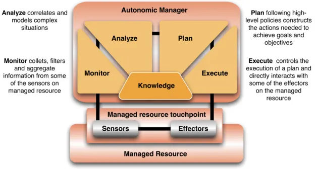
For a system component to be self-managing, it must have an automated method to collect the details it needs from the system; to analyze those details to determine if something needs to change; to create a plan, or sequence of actions, that specifies the nec-essary changes and to perform those actions [1]. In the same white paper IBM presents an architectural blueprint for autonomic computing. They introduce an autonomic man-ager, a component that implements an intelligent control loop - MAPE-K control loop (cf. Fig. 1.1). The name is an abbreviation for Monitor, Analyze, Plan, Execute and Knowledge. The loop is divided into four parts that share knowledge:
• The monitor function provides the mechanisms that collect, aggregate, filter and report details (such as metrics and topologies) collected from a managed resource. • The analyze function provides the mechanisms that correlate and model complex
situations (for example, time-series forecasting and queuing models). These mech-anisms allow the autonomic manager to learn about the IT environment and help predict future situations.
• The plan function provides the mechanisms that construct the actions needed to achieve goals and objectives. The planning mechanism uses policy information to guide its work.
Monitor collets, filters
and aggregate information from some
of the sensors on managed resource
Analyze correlates and
models complex situations
Execute controls the
execution of a plan and directly interacts with some of the effectors
on the managed resource
Plan following
high-level policies constructs the actions needed to
achieve goals and objectives Monitor Analyze Plan Execute Knowledge Autonomic Manager
Managed resource touchpoint
Managed Resource Sensors Effectors
Figure 1.1:MAPE-K control loop
• The execute function provides the mechanisms that control the execution of a plan with considerations for dynamic updates.
The autonomic manager provides sensor and effector interfaces for other autonomic managers and components in the distributed infrastructure to use. Using sensors and ef-fectors interfaces for the distributed infrastructure components enables these components to be composed together in a manner that is transparent to the managed resources [1].
1.4
Organization
The remainder of this document is organized as follows. Chapter 2 is briefly describing the two use cases that serve both as requirement sources and validation elements. All representative scenarios are also synthesized and references to complete descriptions in appendices B and C are given. In chapter 3, envisaged features of the SALTY project are categorized and synthetically described. Relations to the previously listed scenarios are also determined. Perspectives and next steps regarding the project are described in chapter 4. They cover analysis and design of first models and running systems making up the SALTY framework, as well as advances in the use cases. Appendix A details the classification that has been previously introduced. In appendix B the scenarii related to the ”Middleware” use cases are detailed. They are decomposed in scenarii regarding the gLite Grid middleware, the desktop fusion middleware (these two being referred as ”Grid”) and the Petals ESB middleware (this one being referred as ”ESB”). Finally, appendix C describes the scenarii that concern the truck tracking application using multi-means geo-positioning.
CHAPTER
2
Use cases
Use cases of the SALTY project strive to evaluate to capability of the SALTY architecture to capture different types of applications and systems, as well as to validate its capability to manage self-adaptations at different level of granularity. Features sought by the SALTY architecture will be presented in more details in the next chapter, but the use cases have been chosen to cover most of them.
The two major use cases of the project concerns on the one hand different middle-wares and applications dedicated to large distributed systems, and on the other hand, an application using geotracking. The middleware use cases are presented in the follow-ing two sections. Section 2.1 describes the scenarios dedicated to grid management for computation-intensive medical image processing and rendering. In section 2.2, some au-tonomic scenarios related to a large-scale service bus in the context of SOA are presented. The geotracking scenarios are more precisely related to a logistic applications making use of geotracking. They are described in section 2.3. The two main use cases are first summarized below, and then presented in details, with all scenarios in appendices B and C.
2.1
”Grid” Middleware Use Case
2.1.1 Context
Grid infrastructures have become a critical substrate for supporting scientific computa-tions in many different application areas. Over the last decade, world-wide scale Grids leveraging the Internet capabilities have been progressively deployed and exploited in production by large international consortia. They are grounded on new middleware federating the grid resources and administration frameworks and enabling the proper operation of the global system 24/7. Despite all efforts invested both in software devel-opment to achieve reliable middleware and in system operations to deliver high quality of service, grids encounter difficulties to implement the promise of ubiquitous, seamless and transparent computing.
The causes are diverse and rather well identified (complexity of middleware stacks, dependence to many distributed and heterogeneous resources, uncontrolled reliability of the application codes enacted, incompatibilities between software components, diffi-culty to identify sources of errors, challenging scale of the computing problems tackled, etc.). The practice demonstrates that the human administration cost for grids is high, and end-users are not completely shielded from the system heterogeneity and faults. Heavy-weight operation procedures are implemented by the grid administrators and users have to explicitly deal with unreliability issues [9].
neuGRID
In the SALTY project, the grid use case is related to the neuGRID European infrastructure (http://www.neugrid.eu), which aims at supporting the neuroscience community in
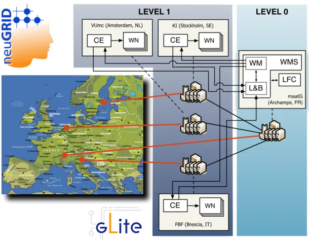
carrying out research on neurodegenerative diseases. In neuGRID, the collection of large amounts of imaging data is paired with grid-based computationally intensive data anal-yses. The infrastructure is developed to run neuro-imaging and data-mining pipelines of algorithms, in particular specializing on Alzheimer’s disease. The neuGRID project is the first project within the neuroscientific community to use the Grid technology. Pipelines manipulated in neuGRID are computationally intensive as they enact a mixture of both short and long running I/O demanding algorithms that are applied over large data sets containing tens of thousands of images. It thus brings underlying Grid resources to their limits and highlights technological bottlenecks. neuGRID is utilizing a Grid infrastruc-ture based on the gLite middleware [8].
gLite Middleware
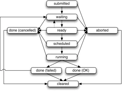
The gLite middleware has been developed as a part of the European project EGEE which delivers a reliable and dependable European Grid infrastructure for e-Science. gLite is architected as a two-levels batch system that federates resources delivered by multiple computing sites. Each site is exposing its Worker Nodes computing units (WN) through a Computing Element (CE) gateway. A high-level meta-scheduler called the Workload Man-agement System (WMS) is used as a front end to multiple CEs. Grid applications are sliced in smaller computing jobs. Each job is described through a Job Description Language (JDL) document. When submitted, a job enters the WMS through a simple web service (WM-Proxy) and it is passed to the Workload Manager (WM) to be queued into a file system-based Task Queue (TQ).
neuGRID data challenges
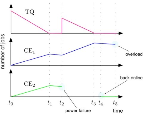
A part of the neuGRID project is a set of validation tests that are run within the infrastruc-ture in order to verify its good performance while meeting user requirements specifica-tion. These performance tests are executed in form of data challenges in which a very large data set of medical images is analyzed hence putting a lot of stress onto the underlying in-frastructure. The second data challenge was running for less than two weeks, and just for comparison, it would have taken couple of years to accomplish the same using a single workstation. During the execution, several failures occur and the most representative has been used to serve as a starting point for identifying scenarios. A power-failure result-ing in a whole site (CE) goresult-ing down, had to be recovered. Submitted jobs were pushed to the other CE where they caused a failure due to an overload. Most of middleware services suffered overload, e.g. the WMS and CE were not able to handle all submitted jobs, a memory leak occurred in one of the WMS subcomponent, etc. Some library in-compatibilities occur on job execution despite the dependencies management system of the middleware. Some scenarios presented below rely on this real world experiments.
Desktop Fusion
In addition to the execution middleware, the neuGrid infrastructure provides means for researches to run specialized viewers and to interact with the Grid directly from their desktop. Desktop Fusion is an integrated new technology which allows for remote execu-tion of applicaexecu-tions. The technology chosen to achieve this is the Open Source version of
the next section.
2.1.2 Summary of the scenarii
There are four scenarii related to the gLite middleware and one related to the desktop Fusion infrastructure.
Scenarii on the gLite middleware are the following:
Scenario 1: WMS overload
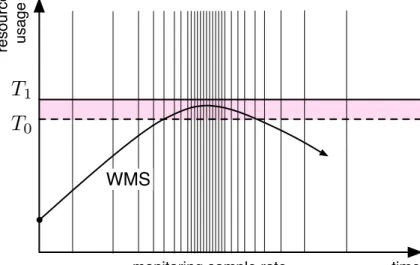
As the WMS component is the gateway to the gLite job management system, it might get easily overloaded, usually by receiving more requests that it can han-dle or due to a software problem in the component itself. To deal with this kind of failure, an additional self-healing control loop should be deployed into the in-frastructure. This loop interacts with the WMS host’s low level operating system probes and periodically monitors resource usage done by WMS process. We define two threshold values for the system. When the first one is reached then WMS is being blocked from all new incoming jobs to be submitted until its resource usage either goes below this threshold or till it reaches the second threshold. If that hap-pens the adaptation mechanism will proceed and restart the WMS. From this basic version, several extensions are expected to be incrementally developed and evalu-ated: to introduce historical values on resource usage, to make the monitoring of resource usage self-adaptive itself, to consider tolerance zone over the threshold, to make the threshold setting automatic, to manage coordination with other loops de-veloped in the next scenarios, to monitor precisely the effect of the feedback loops, to apply finer grained loops on the WMS subcomponents.
Scenario 2: CE Starvation
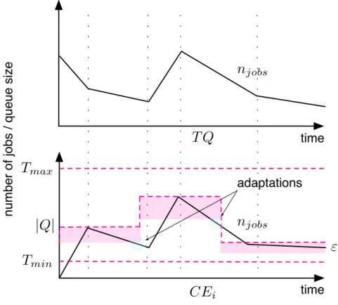
During the data challenge run, when the CE had disappeared because of the power failure, the WMS correctly detected the situation and rescheduled all jobs to the other site that remained available. However, the sudden schedule of many jobs resulted in an complete overload on the other site that had to be restarted in the end. This could have been fixed by setting a smaller queue size. Nevertheless, this introduces a different but more severe issue. If the site receiving all rescheduled jobs was not overloaded and continued to work and the other site appeared again, it would have no jobs to execute. This would result into the situation when one site is very busy and the other completely idle, being able to only work on newly arrived jobs. Therefore, in this scenario, the objective is to keep all computing elements optimally utilized and prevent them from both extremes: an overload, due to large number of jobs getting scheduled, on one hand and a starvation, with no job to process, on the other. The general rule should be to always keep some jobs in the WMS task queue rather than immediately submit them to corresponding CEs. The envisaged solution is to have a control loop for each CE that monitors the number of jobs in the TQ and in the site’s batch queue readjusting the queue size when necessary.
Scenario 3: Job Failures
Job failures can be divided into two categories: the one where the failure is caused by an application specific problem and the other where it is due to a problem in the Grid middleware. The first category includes invalid job descriptions, application
software ”bugs” or invalid input data. The cause related to the middleware may be for example some unresolved library dependencies that lead to systematic fail-ures on some jobs. Indeed a job expresses its requirements in a specific JDL file, but there is no fine-grained manner to express precise library dependencies. Therefore a job might be scheduled to run on a WN that does not satisfy the actual job library requirements. Identifying the exact cause of a job failure requires extensive exper-tise and debugging skills. Furthermore, coordinated investigation over multiple administrative domains is often needed in Grids. To address this problem without resorting to a costly human intervention, it is possible to collect statistics to identify recurring source of failures. A first practical approach consists in building a self-monitoring subsystem that gathers information relevant to job failures. It can then be queried to decide some adaptations based on gradual information about failures as well as statistics such as job executable against failure rate.
Scenario 4: CE Black Hole
Under certain circumstances a CE might malfunction and start to fail all scheduled jobs for some unknown reason. Since it fails all jobs immediately, it will process its queues very quickly hence becoming a black hole in the Grid as it will eat all newly incoming jobs that are matched to its configuration. This scenario is not directly linked to failures observed during the data challenge, but it is a well-known issue in the gLite middleware [6]. The self-healing adaptation in this case involves a control loop that monitors execution time, IO activity using low level operating system probes and results of job execution using the appropriate log. When it observes the black hole pattern – a series of jobs with very short execution time and low disk activity – it will put the CE into a drain mode. Drain mode will be reported back to the ISM (Information Supermarket) and after several minutes, the WMS will no longer submit jobs to it. In this scenario there are multiple options on the concrete loop deployment: one control loop per CE or one master control loop that manages all CEs in the infrastructure. The different pros and cons of these approaches are to be further experimented as one of the aims of the SALTY framework is to facilitate and capitalize such experimentations.
The following last scenario is related to the Desktop Fusion infrastructure management.
Scenario 5: Dynamic Load Balancing
The infrastructure needs to be adapted according to the number of connected users and applications they are using. Taking into account low level resource usage (memory, CPU, etc.) is necessary as well in order to have a better idea of cur-rent load of the system. Thus, when a situation of overload will likely happen, a new Desktop Fusion server will be deployed. It will be configured as part as the load-balanced alias, so that it will be completely transparent for users. This could handle the case where more and more users are connecting to Desktop Fusion, or if a Desktop Fusion server goes down for some reasons. This scenario has some sim-ilarities with the first one on WMS overload and parts of the loops, from models to basic runtime elements, are expected to be shared.
mention that this WMS is connected to the CEs that are part of the production environ-ment of neuGRID so all the tests should be run carefully, not to put any significant load to the underlying infrastructure. For some of the tests an extra effort will need to be done in order to sufficiently test the usability of the approach and of the implementation. This is described per scenario in the detailed appendix.
Besides the initial proof-of-concept tests, executed in the testing environment, there are further plans to incorporate experiments during some larger data and analysis chal-lenges that are part of the future neuGRID project evaluation. Indeed, the latest Data Challenge 3 will consist in validating and assessing the final neuGRID infrastructure. To do this, thousand of MRI scans will be analyzed using at least three different toolkits. This challenge will require a lot of computing power, and the infrastructure will certainly need to be adapted in order to properly handle it and the Salty solution will certainly be really useful for it.
As for the The Desktop Fusion system is based on the FreeNX implementation (http: //freenx.berlios.de/). This later contains already a load-balancing functionality that will be enhanced by the SALTY add-ons. Moreover, new Desktop Fusion servers will have to be concretely deployed. All the neuGRID infrastructure will be migrated from Xen to XenServer soon and proper Desktop Fusion virtual machines will be created. This will allow the SALTY add-ons to deploy these later contacting the XenServer system.
2.2
”ESB” Middleware Use Case
The second set of scenarii aims to support continuity of services in an ESB platform. This continuity is preserved by using the SALTY framework on its services registry and orchestration engine.
2.2.1 Context
An Enterprise Service Bus (ESB) is a middleware infrastructure that provides message-based services for complex systems integration. According to features it provides, it is generally involved in Service-Oriented Architectures (SOA). Petals ESB is an implementa-tion of an ESB based on the Java Business Integraimplementa-tion (JBI) specificaimplementa-tion, which uses the WSDL and Web services concepts. It is one of the first SOA ESBs and aims at provid-ing SOA features, such as service composability, reusability, loose couplprovid-ing, security, autonomy, and adaptability. Another feature of Petals ESB is to be built on a natively distributed architecture. A Petals ESB infrastructure consists in a topology of nodes in which various services are deployed. These nodes communicate with each other within a domain, thanks to a dedicated transport layer using a core exchange model. This speci-ficity allows the Petals ESB architectures to be more efficient in distributed and large scale systems than the state-of-the-art ESB implementations. The service composability is performed in Petals ESB by an orchestration engine able to invoke some services in a structured way.
Self-adaptation of such systems is then a key issue for providing a flexible framework, able to face new kinds of services integration and orchestration within the context of dynamic workflows.
In a SOA ESB context, a common issue identified relates to service composition and orchestration. In particular, a key challenge consists in invoking services within a dynamic
context, which requires adaptations at runtime. We consider for the time being a number of services deployed within a distributed bus and indexed in a distributed registry. Two scenarios have been developed: the first one deals with adaptability of the distributed registry, while the second one addresses a concrete use case that illustrates workflow adaptation needs in the ESB.
2.2.2 Summary of the scenarii
Scenario 1: Self-Organization of the ESB Distributed Registry
In this scenario, we consider a topology of nodes composing the Petals ESB mid-dleware. We define a node containing the master registry while other ones include slave registries. Several services are deployed on each node. The service registry indexes all the available service endpoints and is dynamically updated according to services (un-)installations occurring in the ESB. This mechanism can be prone to instability when nodes fail and, in particular, if it occurs to the node containing the master registry. The SALTY framework can address this weakness by adding an upper monitoring and control layer, based on Service Component Architecture (SCA) sensors/effectors, allowing to know the master registry is available in the current topology of nodes and if not, triggering a recovery process to rebuild a consistent distributed registry. Different solutions can be investigated in order to perform this task, either by rebuilding the whole topology of registries and switching a slave registry to a master one, or by selecting a predefined registry to become the new master one. The implementation of this scenario will involve monitoring nodes through a kind of ”Heartbeat” pattern, and some appropriate actions to clean the crashed ESB node and redeploy every components of the ESB software stack.
Scenario 2: Self-Adaptation of a Crisis Management Workflow
In this use case, we are interested in workflows, which are performed within an ESB and can be reconfigured at runtime. In such ESBs, a workflow implementa-tion typically consists in an orchestraimplementa-tion of services and a well-known standard for such orchestrations is WS-BPEL1. It consists in defining activities providing con-trol structure, invocation and receive mechanisms, correlation and compensation features able to build an execution graph or workflow. This workflow supports several services for working together. They are called partners and are defined thanks to their WSDL interfaces. In our context, an adaptation consists in updating an or-chestration by changing parts of its execution graph or its partners. Indeed, we believe that reflective mechanisms can help in facing new orchestration issues com-ing from the complexity increase of business processes, becomcom-ing longer in time thanks to asynchronous mechanisms and being involved in more and more dy-namic contexts. We build on a legacy use case in order to illustrate the key issues of workflow adaptations. It consists in a crisis management for local authorities, which have to plan for chemical, biological, radiological, and nuclear accident (so called CBRN crisis). This issue, identified in the former ANR SEMEUSE project had some results about dynamic workflows implementing thanks to late binding and semantic match-making extended activities2. In this project, we therefore progress on this scenario by addressing the reconfiguration of the workflow itself at runtime,
of the workflow. Some changes can be reported during a crisis, like an explosion for instance. At the feedback control loop level, workflow reconfiguration can be planned in order to add a branch of execution to manage this explosion. A second adaptation takes into account firemen—reflected as services—functional informa-tion (e.g., temperature, heart rate) and corresponds to services invocainforma-tion reconfig-uration. This particular information allows a feedback control loop to detect that firemen are not available anymore and must be evacuated.
2.2.3 Experimental setup
For the first scenario, the experimental setup will be initially done on dedicated testing servers at EBM Websourcing. It will consist in using a set of virtual servers in which Petals nodes will be installed. JBI components will be used upon these Petals nodes, to simulate a realistic middleware environment with SOAP components to provide external Web services to the bus and SCA components to provide execution environment for SCA services with sensors and effectors. For the second scenario, it will consist in using a set of virtual servers in which Petals node(s) and WSDM monitoring node(s) will be installed.
2.3
Geo-tracking Use Case
2.3.1 Context
After the military for guidance and unit follow-up, geotracking popularized itself in sev-eral domains such as transportation and logistics. Recently, it is more and more adopted in the context of smartphones where numerous applications like route follow-up but also surrounding services (restaurants, hotels, ...) recommendation become widely available. Applications of geotracking currently explode in many areas: logistic, transportation, security, road traffic control, environmental tax collection on vehicles, etc.
In a nutshell, geotracking uses positioning information of mobile (persons, vehicle, ...) to follow them up in time and space so to use this information for application-specific purposes. Geotracking involves at least two entities: a positioning device and a tracking system. Positioning devices use different techniques to locate themselves. Under the global positioning system (GPS), devices triangulate their positions using signals from satellites. Mobile phones can be located from the geographic locus of the cell to which antenna it is currently connected. Finally, similar techniques can be used to locate WiFi cards from their wireless access points.
Positioning devices transmit positions to a tracking system. Most of the time, mobile phone networks are used for this purpose, but alternatives exist (e.g. satellite networks or WiFi). The tracking system is responsible for monitoring the position of mobiles (to which positioning devices are attached) and to trigger reactions when given conditions are met. Typical conditions are: being near, approaching or moving away from some point, approaching or moving away from another mobile, crossing a frontier (in the gen-eral sense), ...
Tracking systems can be directly embedded into end-user applications, such as a truck follow-up system, or can use dedicated platforms that correlate position information from several devices to trigger events sent to end-user applications. These platforms act as complex event processing (CEP) systems, but dedicated to geotracking. GeoHub is
De-veryware geotracking platform, which not only correlates positions but also abstract end-user applications from the specifics of positioning devices and positioning techniques.
Geotracking faces two difficulties that will be addressed within the SALTY project. First, sending positions through a mobile phone network incurs a per message cost for customers which need to be minimized while keeping up with application requirements. Linked to this, and sometimes crucial, sending positions also requires energy from bat-teries which governs the autonomy of the device and so must also be minimized. Second, end-users lack the technical knowledge needed to configure the parameters of the geo-tracking, like the frequency of position reporting from devices, to catch up with applica-tion requirements, like notifying the arrival of a truck at a given locaapplica-tion fifteen minutes in advance with a two-minute tolerance. Other points of interest concern fault-tolerance, i.e. coping with device malfunctions, and the overall workload of the geotracking plat-form which can’t sustain more than a fixed number of position sendings from all of the connected devices to match its quality of service objectives in event processing (e.g. 50,000 positions per minute).
The cost minimization issue will be addressed by dynamically adapting the position reporting, first by modifying its frequency but also by switching back and forth from time-triggered to location-triggered geotracking when possible. As dynamic adaptation is the focus of the SALTY project, complementary adaptation scenarii will be provided by the applications themselves. The geotracking configuration, i.e. defining events to be notified to applications and the type of adaptations needed at run-time, will be addressed by developing an intelligent interactive configuration system.
2.3.2 Summary of the scenarii
The geotracking use cases is developed into four scenarii:
Scenario 1: Long distance truck tracking
Long distance truck tracking is concerned with following up trucks which deliver goods from warehouses to warehouses in a complex network of logistic bases. This scenario is typical either for general in transportation and large-scale distribution. Three different geotracking objectives are considered:
1. Notification of arrival at intermediate destinations, where it is required that trucks arriving at a warehouse notify their arrival enough in advance to let the warehouse coordinator allocate them a port so to optimize port usage and the waiting time of trucks. After notification of their arrival, trucks approach-ing warehouses are still closely tracked in order to take corrective actions if it appears that they will be too late or way in advance.
2. Imposed corridor, where trucks are forced to stay within a corridor around their route to make sure they don’t deviate much of this route. When trucks deviate from their corridor, corrective actions are taken, first to inquire drivers for the reason of the deviation, and if justified, replanning the rest of their route. The system will get inputs from traffic control and weather services so that it may confirm or detect itself conditions justifying a replanning of the route.
Adaptations are sought to minimize the probability to miss a notification, the power consumption and the cost of data sendings through the GSM network. In this sce-nario, they include:
1. frequencies of positioning devices, to increase and decrease them so that low frequencies are used when the truck is far from all of its points of interests, but high when approaching these;
2. type of geotracking, either time-based, where positioning devices push data at planed instant, or location-based, where they push data when passing some point;
3. positioning devices themselves, to use either the GPS or the mobile phone of the truck driver when the GPS is malfunctioning;
4. sleep mode, to manage the power consumption of the devices.
Scenario 2: Short distance truck tracking
The short distance truck tracking scenario deals with fast delivery parcel services where delivery men visit customers either to deliver or pick up parcels. Geotrack-ing can help to shorten the time windows imposed to customer for delivery by following more closely the progress of trucks in order to notify customers when the delivery will be late, and replan the route to deliver most customers on time even by skipping some when necessary. The goal is to maximize the number of customers delivered on time, and therefore their satisfaction, even at the expense of a very late delivery to some of them. This scenario involves the following geotracking objectives:
1. Notification of late arrival, where trucks must deliver within an time window (with some tolerance) several destinations. When the truck positions and its route show that the delivery of a customer cannot be on time, a notification must be sent to the customer no later than a certain notification delay before the end of his delivery time frame. If the delivery is forecasted to be late, a maximum delay is set, such that when the customer cannot be delivered within this delay, it will be rescheduled later in the day, using route replanning to get a new round for the delivery man.
2. Imposed corridor, where trucks are forced to stay inside a certain corridor around their route, otherwise a notification must be sent to the route coordina-tor. If a route replanning is required, a new corridor will be imposed according to the new route. This objective is essentially the same as in the long distance truck tracking use case, so it will not be detailed again here.
Besides the adaptations recalled from the first scenario, this scenario includes a novel one, the replanning of the round of trucks when clients must be skipped. Such an adaptation distinguishes itself from previous ones by possibly requiring some human intervention to decide upon clients to be skipped and replanned in order to take into account business objectives, like giving priority to the best clients, etc.
Scenario 3: GeoHub QoS enforcement
adapt of the overall workload of the GeoHub given its current performance. As the delay between position receptions on the GeoHub and the notification of events to applications must be kept under a limit defined by the quality of service offered to customers, massive adaptations of all positioning device frequencies may be re-quired when this delay becomes too large. This scenario will show the capability of the SALTY architecture to cope with large-scale adaptations of distributed systems. The scenario involves two objectives:
1. Global GeoHub workload management, where a limit on the overall fre-quency of position sendings to the GeoHub must be maintained under a cer-tain limit corresponding to Deveryware’s QoS objectives. When the workload exceeds this limit, all of the connected positioning devices will be required to lower their frequency, to get a decrease in the overall workload of the GeoHub. 2. Local frequency limits management, where each positioning device and their autonomic managers will observe an upper bound on the frequency of its posi-tion sendings. Such limits will be adapted at run-time according to the overall workload of the GeoHub and the relative importance of the current geotrack-ing objectives currently drivgeotrack-ing the use of this device.
Adaptations will mainly concern the frequencies of positioning devices. For the first objective, the adaptation will itself be large-scale, targeting all of the currently connected positioning devices. For the second objective, a more local adaptation is sought, but still requiring care, as heuristics may be used that could potentially develop into a large-scale exploration of the currently connected devices to find one that has available resources to share.
Scenario 4: Decision-making Modeling at Design-time
This scenario is of a different nature compared to the previous ones. One of the goals of the SALTY project is to build an interactive tool, the decision-making mod-eling at design-time tool, to help non-specialist end-users in eliciting their business objectives and criteria for adaptation for their geotracking applications. As such a tool cannot be fully general, the geotracking use case will provide us with a first context for design exploration. Generality of the tool will be sought through the use of an adaptable database for parameters such as dictionaries, model-driven in-teraction patterns (question/answer, menu, etc.), etc.
2.3.3 Experimental setup
Testing and experimenting applications that have at least part of their behavior bound to real time is inherently difficult. In the case of truck tracking, the real time behavior comes from the need for real positions sometimes correlated with real geographical positions and artifacts, such as roads and their speed limits, warehouse positions, waypoints, etc.
Hence, it will not suffice to merely generate input data and run an application on a standard computer. The experiment will have to take place in the real time frame, posi-tions and transit times being realistic to some extent. On the other hand, as scalability to large numbers of geotracked vehicles is a key issue in the SALTY project, it is not realistic
threads on stock computers, executing simulated travels. The idea is to get a planned route, using planning services such as ViaMichelin, and then plan a per truck simula-tion scenario to be run around that route. Each truck simulasimula-tion will exhibit required notifications, and therefore adaptation scenarii. In some cases, incidents, like device mal-functions, traffic jams, etc. will be injected into the scenarii to trigger the corresponding adaptations.
As a large number of such truck simulation scenarii will be required, they will be generated automatically from the following sub-scenarii and their variants. A machine-readable description of these will be constructed, and fed into a simulation scenarii gen-erator that will give an executable scenario in another machine-readable format used by specifically developed truck and positioning device simulation programs. To our knowl-edge, no such simulation platform exists to date. It will be a contribution of the SALTY project that could be reused by Deveryware in the future to test other enhancements of their platform.
CHAPTER
3
Features
In order to provide key success indicators, the SALTY framework is developed following a feature-driven approach. This approach consists in an iterative and incremental devel-opment process, specific to software. It is usually described as an agile method, focusing on a client-valued functionality (feature) perspective. This process is decomposed into five activities: overall model development, feature list building, planning by feature, de-sign by feature, build by feature. The first three activities are usually sequential, whereas the final two activities are iterative and should iterate on features.
In our context, such a feature may range from a functionality of the autonomic frame-work to some characteristics on how it is built or some resulting properties of using the framework itself. We then first determined the set of features based on the study and classification of the use cases. As the framework architecture will be sketched in the fol-lowing months, we will determine the success indicators on each feature together with some priorities. This will enable the classic stages of planning, design and build by fea-ture.
In the next paragraphs, the features are organized into four categories, each address-ing a particular point of the project:
I. Large-Scale environment, II. Self-adaptation,
III. Salty Framework building and architecture,
IV. Model-driven engineering in the construction of very large self-adaptive systems. Inside each category, we define sub-groups of features focusing on main issues to be tack-led. For each feature, we briefly present how use cases are related to it. In the description, UC1 will correspond to the Middleware use case. To precise the platform involved by the feature demonstration, we note UC1 GRID to reference the scenarii that are related to the gLite middleware or the desktop fusion bus, and UC1 ESB denotes the scenarii related to the Petals Enterprise Service Bus (ESB). Finally, UC2 will correspond to the Geo-tracking use case.
It must be noted that the list of features presented below is maintained on the internal collaborative web site of the project.
3.1
F.I. Tackling Very-Large-Scale Environments
The following features outline properties induced by self-adaptation of very large sys-tems. We have identified four main dimensions to be dealt with:
A. the intrinsic distribution of these systems and the necessary distribution of the man-aging infrastructures themselves,
C. the large number and the diversity of managing entities, D. the confidentiality of the managed system.
3.1.1 F.I.A. Supporting the distribution of the managed system and the man-aging infrastructure
This feature decomposes into the following ones:
FI.A.1. Supporting the distribution of the managed system.
FI.A.2. Supporting the distribution of the managing infrastructure.
Description
Supporting distribution of the managed system includes, for example, the delays in the monitoring of remote services, the need to integrate monitoring data from different re-mote sites, the time-stamping of all monitoring data to correlate them prior to their use and the coordination of adaptation decisions implying modifications at different remote sites.
Supporting distribution of the managing infrastructure includes the need to synchronize distributed adaptations without impacting the performance of the controlled system, and the need to supervise the adaptation with appropriate means (distributed synchroniza-tion, multi-agents system approaches, approaches from intelligent and collective robotics to the planning of adaptations).
Link with use cases
FI.A.1. & FI.A.2. UC1 GRID part involves a distributed middleware (1) and all auto-nomic elements must be coordinated in a distributed way (2).
FI.A.1. & FI.A.2. UC1 ESB part is itself widely distributed (1) and needs to be controlled at node level, that is to say, sensors, effectors and MAPE loops must be dissemi-nated over the ESB topology (2). Thus, UC1 ESB should use scalable architecture as peer-to-peer for sensors.
FI.A.1. & FI.A.2. UC2 is involved as the geoHub infrastructure is a large distributed event-based system (1) and all autonomic elements must be deployed and coor-dinated appropriately on this infrastructure.
3.1.2 F.I.B. Supporting the large number and the diversity of managed entities This feature set addresses the following dimensions:
F.I.B.1. Large Amount of data stored, accessed and manipulated.
F.I.B.2. Complexity of connections and interdependencies.
Large scale systems are known as systems of unprecedented scale in some of the previous dimensions. These systems are then necessarily decentralized in a variety of ways and constructed from heterogeneous parts. This complexity imposes the need for evolving continuously with conflicting needs. In the use cases, we address each of these dimen-sions to validate the adequacy of the Salty framework when applied on such systems.
Link with use cases
F.I.B.1. & F.I.B.3. UC1 GRID part is concerned by these features, as the scenarii will be applied in the context of the Alzheimer’s disease analysis pipeline, which involves very large set of data and is deployed on a neuGRID infrastructure involving a large number of jobs.
F.I.B.2. UC1 GRID part deals with the complexity of connections and interdependencies between the different elements of the GRID. Some of these interdependencies are ”implicit” and control mechanisms should be applied to evaluate their interactions.
F.I.B.4. UC1 ESB part addresses this feature as the case study corresponds to a Crisis Management System where the number of alternatives and failures to explore is a priori unknown. Adaptation to the crisis context should support the need for unanticipated dynamic adaptation.
F.I.B.5. All the use cases are potentially concerned by this feature as soon as MAPE loops can interfere in the application itself.
3.1.3 F.I.C. Supporting the large number and the diversity of managing enti-ties
This feature decomposes into the following ones:
F.I.C.1. Large number of adaptable entities.
F.I.C.2. Large number of loops on the same entity or group of entities.
F.I.C.3. Large number of events triggered through loops.
F.I.C.4. Important variability in the controlled system.
Description
Large-scale means that the architecture and the algorithms will need to scale. The control system, made of a large number of MAPE loops over large number of entities, trigger-ing large number of events, must coordinate themselves and implement system-wide adaptations. Peer-to-peer coordination algorithms as well as multi-agents inspired co-ordination algorithms, are intended to address this issue for the coco-ordination of MAPE loops on a large scale. There is thus a large number of possible architectural patterns of organization between the different involved software entities.
Link with use cases
F.I.C.1. & F.I.C.2. & F.I.C.3. UC2 adaptations have to do with these features, provided that the GeoHub and the positioning devices are viewed as a complex event pro-cessing system and probes respectively. Controlling the workload of the GeoHub implies controlling the frequencies of all the positioning devices sending data.
F.I.C.2. & F.I.C.3. & F.I.C.4. UC1 GRID part is concerned by these features, as coupling scenarios lead to several complex loops to be coordinated on the same middleware entities, while triggering a large number of events. Different architectures of the control system are also envisaged.
F.I.C.4. UC1 ESB needs to implement scalable algorithms and frameworks in order to manage system-wide adaptations. It should deal with the variability of the archi-tecture. It is conceivable within the context of a federated architecture with several domains having their proper configurations, service policies and adaptation rules. 3.1.4 F.I.D. Preserving the level of confidentiality of the managed system
Description
Much of the data manipulated in the SALTY use cases have privacy properties. In the Salty project our intent is to support risk analysis, through which targets and vulnera-bilities in the system architecture are identified, and specific security requirements are derived from general security objectives (e.g. secrecy of information).
Link with use cases
F.I.D. UC1 GRID part should ensure that access WMS and CE runtime information are restricted to authorized systems.
F.I.D. In UC1 ESB part, security must be managed as one of the main ESB features.
F.I.D. In UC2, positions can be anonymized before being sent to MAPE loops. In some cases, they can be encrypted (programmable devices). Isomorphic transformations can also be applied to make impossible their relation to a precise geographic loca-tion for intruders.
3.2
F.II. Supporting the Adaptation of Complex Systems-of-Systems
The following features concerns self-adaptation. According to self-adaptive system clas-sification, these features specifically focus on the dimensions ”Change”, ”Mechanisms” and ”Effects”, as described in section 1.3.
The features are decomposed according to the three following dimensions: A. Reflecting feedback control loops as first class entities,
at-This feature decomposes into the following ones:
F.II.A.1. Being able to coordinate several loops at different levels and scopes (from lo-cal to large-slo-cale) making decisions over the same controlled entities in order to produce coherent adaptations.
F.II.A.2. Making the control conscious of its own quality and self-adaptive to achieve stability and efficiency.
F.II.A.3. Attacking control situations with different temporal constraints from tight tim-ing constraints to best effort adaptations.
Description
Given the dynamicity and complexity of large-scale systems of systems, their control loops cannot be defined in advance to implement fixed policies, but rather adapted at run-time. To achieve such adaptations, a reflective representation must be sought to get MAPE loops as first-class entities, which one can reason about, modify, compose, and reuse dynamically. In real-life applications, decisions made by local MAPE loops may affect each others, at all system scope levels from client-server interactions to global con-straints. To enforce integrity constraints, such local decisions cannot contradict each oth-ers, so the loops must coordinate themselves to achieve collaborative decisions. To deal with a very large set of MAPE loops, we will study coordinated loops based on an hybrid locally hierarchical and globally peer-to-peer architecture, instead of purely hierarchical (which would not scale well). Autonomic managers are components with specific needs in terms of initialization, and meta-control. This can be put under a specific workflow to manage their life-cycles. Autonomic manager, as components, can also be adapted. The architecture shall provide for this by adding autonomic managers to them. The sys-tem being distributed and large-scale, MAPE loops need not be always implemented as a unique module but shall take into account the latencies and time requirements to de-ploy itself in such a way to compute good adaptation policies while satisfying the timing constraints of the control process, (maximum time between triggering conditions and the corresponding execution of the required adaptation).
Link with use cases
F.II.A.3. UC1 GRID is based on best effort adaptation, when UC2 should deal with tight timing constraints.
F.II.A.1. & F.II.A.2. All use cases are concerned by these two features as soon as they mix several adaptations from several scenarii.
3.2.2 F.II.B. Supporting the monitoring of heterogeneous and complex data and their quality attributes
F.II.B.1. Handling explicitly the quality of information in the configuration of the moni-toring.