HAL Id: inria-00407788
https://hal.inria.fr/inria-00407788
Submitted on 27 Jul 2009
HAL is a multi-disciplinary open access
archive for the deposit and dissemination of
sci-entific research documents, whether they are
pub-lished or not. The documents may come from
teaching and research institutions in France or
abroad, or from public or private research centers.
L’archive ouverte pluridisciplinaire HAL, est
destinée au dépôt et à la diffusion de documents
scientifiques de niveau recherche, publiés ou non,
émanant des établissements d’enseignement et de
recherche français ou étrangers, des laboratoires
publics ou privés.
taking into account the full specification of the
membrane
Paul Naoumenko
To cite this version:
Paul Naoumenko. An extension for ADL definition of GCM components, taking into account the full
specification of the membrane. [Technical Report] RR-7001, INRIA. 2009. �inria-00407788�
a p p o r t
t e c h n i q u e
ISRN INRIA/R T--7001--FR+ENG Domaine 3An extension for ADL definition of GCM
components, taking into account the full
specification of the membrane
Paul Naoumenko
N° 7001
Juillet 2009
Centre de recherche INRIA Sophia Antipolis – Méditerranée
Paul Naoumenko
∗Domaine : Réseaux, systèmes et services, calcul distribué Équipes-Projets OASIS
Rapport technique n° 7001 — Juillet 2009 — 20 pages
Abstract:In this document we propose a set of extensions for the structure of the current ADL files used to describe architectures of GCM components. Those extensions introduce the full specification of the membrane, a better separation between the functional and the non-functional part of the component, and the support for communications between the membrane and the functional content. The extensions proposed in this report follow the model which was proposed in [1].
Key-words: component model, architecture description language, non-functional aspects
Résumé :Dans ce document nous proposons un ensemble d’extensions pour la structure actuelle
des fichiers ADL, utilisés pour décrire les assemblages de composants GCM. Ces extensions in-troduisent la spécification exhaustive de la membrane, une meilleure séparation entre la partie fonctionnelle et non-fonctionnelle des composants, et les communications entre le contenu fonc-tionnel et la membrane. Les extensions que nous proposons sont basées sur le modèle proposé dans [1].
1
Introduction
This document is a technical report, which goal is to introduce and illustrate possible changes to do in the current GCM ADL file. It concerns improving adls by giving the possibility to design component systems inside GCM membranes.
Currently, there is no possibility to do so. The first proposition to define a component mem-brane was to specify the reference to an adl file inside the “controllerdesc” tag of traditional GCM adls. This was a pretty good idea, as the description of the membrane can be done in a separate file (just like in previous versions of GCM and Fractal frameworks in general), with no modification of the adl dtd. In this file we could specify the controller system as a classical com-ponent assembly (with no difference compared to a classical adl). We call this file the NF adl. The standard way of specifying a component assembly is to include it inside a global “defini-tion" tag, which represents a composite. Thus, the membrane is also specified as a composite. The interfaces defined in this adl represent NF interfaces of the host component (the “owner" of the membrane), that we simply call NF interfaces. We introduced the concept of the “dis-solved membrane”: the composite wrapping the component controllers is not created : only the interfaces, the inner component system, and the bindings are created.
Taking this NF adl as a starting point, several issues have to be considered: • The definition and integration of NF interfaces.
• The definition Nf component systems
• The specification of functional internal interfaces • The definition of interceptors
• The definition of a development process to ease the design of a component with Nf com-ponents in the membrane
2
Development process and roles
According to Szyperski [2], one person should be able to deal with the design and the imple-mentation of one component. In our case, we will need at least two specialists: one in charge of designing the functional content (the functional assembler) of the component, and one to design the Nf part (the Nf assembler) of the component. We believe that those two persons can work separately, relying only on interfaces between functional and non-functional worlds and constraints of the component architect (the person who expects the component to be produced).
2.1
The component architect
The component architect is a person who wants to assemble a component system out of already existing components. Refering to the book of Clemens Szyperski, what we call the component architect is in fact the component assembler: ”A component assembler takes application re-quirements, selects appropriate components, and assembles these”. In our case, the component assembler needs to specify the functional interfaces of components he wants to include inside his system and may be also the Nf interfaces, as in the case of Fractal, he also has to know what non-functional features he needs the components of his system to have (besides the ones that are part of the framework). For this, he needs to define what are the (re)configuration possibilities of these components. We suppose that he asks specialists to produce some of the components that will be integrated into his system. He can specify the functionality of the components he needs in several ways, depending on his expertise. First of all, he can specify the function-ality of a component in an abstract way, starting with handwritten text. He can also express some preferences regarding the signatures of the interfaces he wants the components to expose, the operational behavior of the component’s interfaces and finally an elaborated semantic de-scription. The specialists will have to take those constraints into account when designing and developing the components.
2.2
The functional assembler
For a primitive component, the functional assembler is may be what Szyperski calls a compon-ent developer. This person is in charge of producing the business code, according to the abstract functional specification of the architect. Instead of developing his own pieces of code, the func-tional assembler can also reuse some already existing components (or make them produced) and assemble them inside a composite component in order to fulfill the wishes of the component ar-chitect. Somehow, at the level of the composite component, the functional assembler becomes the component architect by choosing and putting some constraints on the components he needs. When designing the functional content of a component, the only specification that the func-tional assembler takes into account is the abstract funcfunc-tional description of the architect. He then has the possibility to choose whatever he considers best to implement the functionality of the component he is assembling in terms of the interfaces(signatures) and their operational behavior. Indeed, the interfaces that give access to the functional content of a component are in-ternal interfaces. Those inin-ternal interfaces can be entirely specified by the functional assembler. If the component architect expresses some constraints on the interfaces exposed by the compon-ent, it is up to the Nf assembler to match these constraints by including inside the membrane the components that will consistently connect external interfaces (from the specification of the architect) to internal ones (chosen by the functional assembler). If we consider the new possib-ilities of GCM components(bindings from the membrane to the content and from the content to the membrane), the functional assembler has to know the specification of the Nf interfaces of the components he is assembling because he will have to choose the Nf interfaces of the func-tional components that will be accessed from the membrane. Accordingly, the Nf assembler will include those interfaces as internal interfaces of the membrane. For connexions between the content and the membrane, the functional assembler can specify the Nf internal interfaces the membrane should expose. The process of choosing the interfaces between the membrane and the content should be performed in several refinement steps, because the Nf assembler may also put some constraints on the Nf interfaces exposed by components inside the functional con-tent. At the end, both specialists must agree on a set of interfaces between the content and the membrane.
2.3
The non-functional assembler
The first job the Nf assembler does is to choose the external interfaces of the component. For functional interfaces, if the component architect did not express any constraints, the best solu-tion for the Nf assembler is to define external interfaces corresponding to the internal interfaces defined by the functional assembler. If the component architect expressed any preferences, the Nf assembler must make sure that the external interfaces will communicate consistently with the internal ones(by including for example the corresponding interceptors). The Nf assembler chooses the Nf interfaces exposed by the membrane according to the specification of the com-ponent architect. Then he has to choose and assemble the comcom-ponent controllers that will super-vise the functional part of the component by taking into account the environment in which the component will run and the points of interaction with the functional content. We take the as-sumption that with primitive components it should be not possible to perform structural recon-figurations (for example, dynamically replace the functional content) but only reconrecon-figurations based on parameter tuning.
2.4
Internal interfaces
There is an important point to discuss, concerning the way those interfaces are defined and the constraints that we put on them. As in some case we need to explicitly define internal interfaces, we need to introduce a specific tag. We propose to add a new keyword for the interface role, like “internal-server” and “internal-client”. In the next sections, we will discuss about the constraints that we put on internal and external interfaces.
Generally, we propose to give freedom on the number of external and internal interfaces of any component.
2.4.1 Primitive components
From the Fractal specification, there are no internal interfaces for primitive components, as the set of internal interfaces is accessed through the ContentController, which is a controller that is specific to composite components. From what we said in Section 2.2, we consider that internal interfaces for primitive components are necessary. Indeed, the functional assembler has the pos-sibility to choose whatever he considers best to implement the functionality of the component in terms of the interfaces(signatures) and their operational behavior. However, we put an aditional constraint on primitive components: each external functional interface has a complementary in-ternal interface of the same name, signature, and contingency , and of opposite role. This is a first version of the constraints (that may be improved) justified by the fact that external interfaces of primitive components are tightly coupled with its content (inside an adl, the content is specified by a class that implements the external server interfaces and contains the external client inter-faces of the primitive component). What is the point of introducing those internal interinter-faces? This will be an improvement of the old way of intercepting used in the GCM framework. At the moment, if there is any interceptor defined, it intercepts any call on a functional interface. With internal interfaces, we will be able to specify interceptors that are specific to an external interface (in the case on input interceptors) and connected to a specific internal interface. Interceptors are presented with more details in Section 4.1. The cardinality of any internal interface should be singleton, no matter what is the cardinality of the external interface. This is because the sigleton interface does not brake the behavior of an external interface. For example, if an external server interface is gathercast, after all the calls are synchronized, a call is emmited on the correspond-ing internal interface which will simply forward the call to the content without addcorrespond-ing any extra behavior. Symmetrically, if an external client interface is multicast, the content will first perform a call on the corresponding server internal interface, which will forward the call without doing any change to the external interface or to an interceptor if there is one.
We are still working on those constraints, trying to figure out a way to introduce more flex-ilibity for primitive components.
We can think of several ways of accessing those internal interfaces, which for me is just an implementation issue(which controller will give access to the internal interfaces??). Thte good thing is that we don’t need to define them inside an adl because they are somehow implicitely defined.
2.4.2 Composite components
From the Fractal specification, we can read: “... each internal functional interface has a com-plementary external interface of the same name, signature, contingency and cardinality, and of opposite role (but the converse is not necessarily true)”
We propose to give freedom on the number of external and internal interfaces for composite components. This means that the content section of a composite may define an arbitrary set of internal interfaces and that the set of external interfaces may be totally different both in number and concerning the usual attributes of an interface (signature, role, cardinality and contingency). As explained earlier, it is up to the Nf assembler to connect the interfaces in a consistent way, by making sure that the functionallity of the component is implemented.
3
Designing a membrane with components
Here, we will introduce several ways of defining component systems inside GCM membranes.
3.1
Non-functional type
With the idea of defining nf systems inside adls, the first thing to consider is how to explicitely define the non-functional type of a component(the set of Nf interfaces of the component). The most intuitive decision is that it has to be defined the same way as the functional type. Figure 1 gives an example of a NF type. This way, this NF type can be included inside adls as a preexisting Nf type, with the help of the extends tag(extends=“org.objectweb.NFType”). Notice that the
definition of internal interfaces is allowed for the Nf type. The org.objectweb.NFType can be extended by the adl file that is specific to the membrane(see for example Figure 7). Further in this document, we will present how to use the Nf type.
1 <?xml version="1.0" encoding="ISO-8859-1" ?>
2 <!DOCTYPE .... >
3 <definition name="org.objectweb.NFType">
4 <interface signature="org.objectweb.fractal.api.control.BindingController
" role="server" name="binding-controller"/>
5 <interface signature="org.objectweb.fractal.api.control.
LifeCycleController" role="server" name="lifecycle-controller"/>
6 </definition>
Figure 1:Specifying the non-functional type
3.2
Primitive component
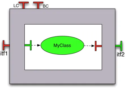
Here, we will describe various ways of defining a primitive component, starting with a descrip-tion compatible with the old adl, ending with fully-fledged component systems for the mem-brane. In Figure 3 there is a standard description of a primitive component. In Figure 2, there is the corresponding graphical representation. This description is compatible with the old GCM adl. The keyword “primitive” means that a default file will be chosen for the description of the membrane’s structure.
Notice that the internal interfaces that can be seen on Figure 2 are implicit (are not declared in the adl), because they correspond to the external interfaces, as explained in Section 2.4.1. Never-theless, those internal interfaces need to be explicitely mentionned when statically defining the binding with an interceptor. The dashed bindings that you can see between the class and the internal interfaces are not real bindings. They only mention an implicit connection between the the content and those interfaces.
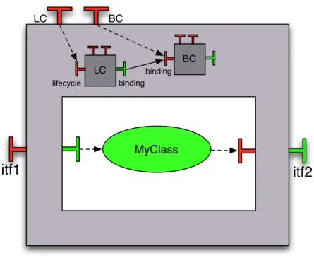
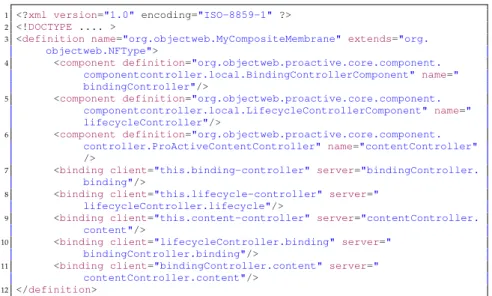
In Figure 5, there is the definition of a primitive component with a componentized mem-brane. In Figure 4, there is the graphical representation of this system. The particularity of this adl is that the membrane is defined in an inline component system (inside the same adl) in the controller section (between lines 7 and 15). Indeed, the controller section has been extended in order to give the possibility to define interfaces, components and bindings. Interfaces declared in this section are either NF interfaces exposed by the membrane, or references to functional in-terfaces, which will be discussed in Section 4. Components declared in this section are only NF components. The bindings are either bindings connecting elements of the membrane or bind-ings connecting interceptors to functional interfaces. It is important to notice that this controller section contains only interfaces, components and bindings, with some other optional properties (cf. the dtd of the new adl). If any other section is included inside the controller one, it will be ignored (for example, no controller section as this section is already defining the membrane).
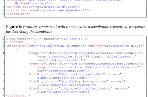
An alternative for the same architecture is described in Figure 6 and Figure 7. Those two figures show that the membrane can be defined in a separate file and then referenced in the main file.
One of the main goals of this new adl structure is to reflect the separation of roles during the design process of a component like explained in Section 2.
3.3
Composite component
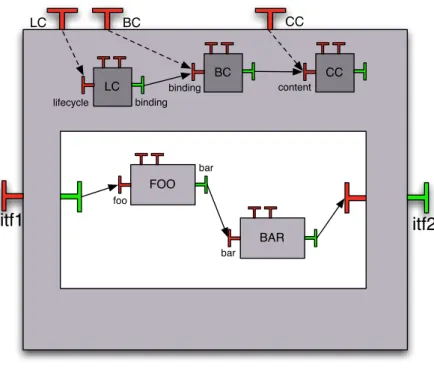
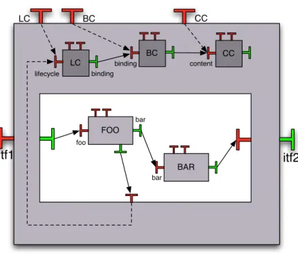
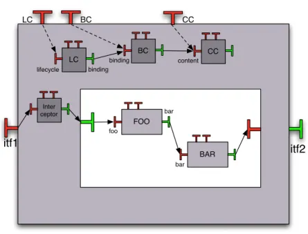
In this section, we are going to introduce how to define the adl of a composite component ac-cording to the new specification. We will define various and equivalent ways, starting from definitions compatible with the old adl, ending with membranes equipped with GCM compon-ents and interceptors. In Figure 8, we graphically represented a simple composite component, with a set of functional components inside its functional content and a set of Nf components inside its membrane. In Figure 9, there is the corresponding adl description. Notice that this adl reuses some previously introduced concepts, like using an external file for the definition of its
MyClass
LC BC
itf1
itf2
Figure 2:Graphical representation of a simple primitive component
1 <?xml version="1.0" encoding="ISO-8859-1" ?>
2 <!DOCTYPE .... >
3 <definition name="org.objectweb.primitivecomponent">
4 <interface name="itf1" role="server" signature="org.objectweb.
MyServerInterface"/>
5 <interface name="itf2" role="client" signature="org.objectweb.
MyClientInterface"/>
6 <content class="org.objectweb.MyClass"/>
7 <controller desc="primitive"/>
8 </definition>
Figure 3:ADL description of a simple primitive component
membrane. Of course, for composite components, defining the membrane can be done the same way as presented for primitives(inline component system, separate file). Here, the file describ-ing the membrane is described in Figure 10. It is very similar to the previous description of the membrane (Figure 7), except the fact that the composite additionally has inside its membrane the ContentController.
Going back to Figure 9, the functional content of the composite is described as in the old versions of the adl. Some alternatives to describe the same composite are presented in Figures 11, 12 and 13. In Figure 11, there is a new structure that we introduced. Indeed, just like the inline controller section, we can also define an inline content section. We can notice that on lines 7 and 8, some interfaces are defined. Inside the content section for a composite component, defined interfaces are internal ones. In this particular case, the internal interfaces correspond to the external ones (same name , same signature, same contingency, but inverted role). The role is opposite, to correspond to what we can see on the graphical representation. The adl file presented in Figure 11 shows a particular usage of the content section. It introduces some redundancy inside the same file in the case internal interfaces are corresponding to the external ones. In this case, the definition of the system should be done like in Figure 9. If the set of internal and external interfaces is different, the representation of Figure 11 can be adopted. For small systems, it offers some clarity, as everything is defined inside the same file. However, it it highly recommended to choose the approach described in Figures 12 and 13.
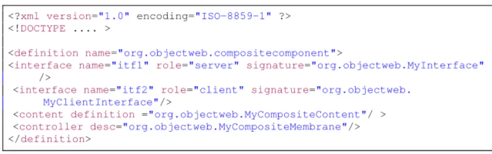
In Figure 12, the description follows the separation of roles introduced earlier in Section 2, with content and membrane described in two separate files.
MyClass
LC BCitf1
itf2
LC BC lifecycle binding bindingFigure 4: Graphical representation of a primitive component with componentized membrane
1 <?xml version="1.0" encoding="ISO-8859-1" ?>
2 <!DOCTYPE .... >
3 <definition name="org.objectweb.primitivecomponent">
4 <interface name="itf1" role="server" signature="org.objectweb.MyInterface"
/>
5 <interface name="itf2" role="client" signature="org.objectweb.
MyClientInterface"/>
6 <content class="org.objectweb.MyClass"/>
7 <controller>
8 <interface signature="org.objectweb.fractal.api.control.
BindingController" role="server" name="binding-controller
"/>
9 <interface signature="org.objectweb.fractal.api.control.
LifeCycleController"role="server" name=
"lifecycle-controller"/>
10 <component definition="org.objectweb.proactive.core.component. componentcontroller.local.BindingControllerComponent"
name="bindingController"/>
11 <component definition="org.objectweb.proactive.core.component. componentcontroller.local.LifecycleControllerComponent"
name="lifecycleController"/>
12 <binding client="this.binding-controller" server="
bindingController.binding"/>
13 <binding client="this.lifecycle-controller" server="
lifecycleController.lifecycle"/>
14 <binding client="lifecycleController.binding" server="
bindingController.binding"/>
15 </controller>
16 </definition>
Figure 5:ADL description of a primitive component with componentized membrane: inline NF system
3.3.1 Connexions membrane-content and content-membrane
Membrane-content and content-membrane connexions are defined in the content section of a composite. Once again, this is done following the graphical intuition: graphically, the arrows representing connexions between the membrane and the content and vice-versa are inside the
1 <?xml version="1.0" encoding="ISO-8859-1" ?>
2 <!DOCTYPE .... >
3 <definition name="org.objectweb.primitivecomponent">
4 <interface name="itf1" role="server" signature="org.objectweb.MyInterface"
/>
5 <interface name="itf2" role="client" signature="org.objectweb.
MyClientInterface"/>
6 <content class="org.objectweb.MyClass"/>
7 <controller desc="org.objectweb.MyMembrane"/>
8 </definition>
Figure 6:Primitive component with componentized membrane: reference to a separate file describing the membrane
1 <?xml version="1.0" encoding="ISO-8859-1" ?>
2 <!DOCTYPE .... >
3 <definition name="org.objectweb.MyMembrane" extends="org.objectweb.NFType"
>
4 <component definition="org.objectweb.proactive.core.component. componentcontroller.local.BindingControllerComponent"
name="bindingController"/>
5 <component definition="org.objectweb.proactive.core.component. componentcontroller.local.LifecycleControllerComponent"
name="lifecycleController"/>
6 <binding client="this.binding-controller" server="
bindingController.binding"/>
7 <binding client="this.lifecycle-controller" server="
lifecycleController.lifecycle"/>
8 <binding client="lifecycleController.binding" server="
bindingController.binding"/>
9 </definition>
Figure 7: Primitive component with componentized membrane: the content of the separate file
content. In Figure17, there is a graphical representation of a connexion between the membrane and the content. Figures 18 and 19 represent the corresponding adl description.
Similarly, Figures 14, 15 and 16 represent connexions between the content and the membrane. For membrane-content connexions, the functional assembler must declare references to in-ternal interfaces of the membrane. Those references are declared the same way as any interface is declared. Inside the functional content Nf interfaces are not allowed, which means that if an Nf interface is declared, then we can be sure that this is a reference to an internal Nf interface(which must itself be declared in the Nf adl).
Figures 15, 16, 18 and 19 are extensions of Figures 13 and 10. They introduce only additional declarations made to the content and the membrane of the composite in order to connect the functional and non-functional worlds. In Figures 15 and 18 representing the content of the com-posite, we can see the reference to the internal Nf interface of the membrane on line 6 and the binding with this interface on line 8. The name of the interface should be the same as in the Nf adl (where this interface must be declared, like in Figures 16 and 19). Notice that inside the content section, we don’t have to keep the same role description as the declaration in the Nf adl. Indeed, all the interfaces declared inside the content section(functional interfaces or references to Nf interfaces) are internal ones. Thus, we don’t need to mention that the interface is internal. Nevertheless, if the internal role is mentioned, it will be accepted.
Figures 16 and 19 represent the additional declarations added to the membrane for con-nexions between functional and Nf worlds. On line 5, we can the declaration of the internal interfaces. In the membrane file, the internal role must be mentioned, as inside the membrane (contrary to the content section) both external and internal interfaces are declared.
4
Defining interceptors
The idea is that an interceptor is connected to a functional interface, from which it will seam-lessly intercept method calls. When an interceptor intercepts a method call, it can decide what
itf1
itf2
FOO BAR LC BC LC BC lifecycle binding binding foo bar bar CC CC contentFigure 8:Graphical representation of a composite component
1 <?xml version="1.0" encoding="ISO-8859-1" ?>
2 <!DOCTYPE .... >
3
4 <definition name="org.objectweb.compositecomponent">
5 <interface name="itf1" role="server" signature="org.objectweb.MyInterface"
/>
6 <interface name="itf2" role="client" signature="org.objectweb.
MyClientInterface"/>
7
8 <component definition="org.objectweb.Foo" name="foo"/>
9 <component definition="org.objectweb.Bar" name="bar"/>
10 <binding client="this.itf1" server="foo.foo"/>
11 <binding client="foo.bar" server="bar.bar"/>
12 <binding client="bar.itf2" server="this.itf2"/>
13
14 <controller desc="org.objectweb.MyCompositeMembrane"/>
15
16 </definition>
Figure 9:Description of a composite close to the old adl
to do with it. The idea with interception is to perform additional processing before delegating the call to the interface it was adressed to. This additional processing can be delegated to NF components located inside the membrane. I think that once processed, the call has to return to the functional world (sent to a functional interface), because originally it was adressed to a functional component. This question still remains as pending. Indeed, we could imagine scen-arios where an intercepted call is not sent to the functional component in charge of processing it: according to some policies, a particular functional call is not forwarded to the corresponding functional component. There are two types of interceptors : input and output. Input intercept-ors intercept incoming calls on a functional interface. Output interceptintercept-ors intercept calls emitted from a functional interface.
The problem of adding interceptors inside the NF adl is that they have to be connected to functional interfaces. But the definition of functional interfaces is not included in the NF adl, as they are defined in the “functional” part of the adl. One solution to solve this problem is to define interceptors outside the Nf adl. We do not want to do this, as we want follow the graphical intuition and keep interceptors inside the membrane. Just like for non-functional
in-1 <?xml version="1.0" encoding="ISO-8859-1" ?>
2 <!DOCTYPE .... >
3 <definition name="org.objectweb.MyCompositeMembrane" extends="org.
objectweb.NFType">
4 <component definition="org.objectweb.proactive.core.component.
componentcontroller.local.BindingControllerComponent" name="
bindingController"/>
5 <component definition="org.objectweb.proactive.core.component.
componentcontroller.local.LifecycleControllerComponent" name="
lifecycleController"/>
6 <component definition="org.objectweb.proactive.core.component.
controller.ProActiveContentController" name="contentController"
/>
7 <binding client="this.binding-controller" server="bindingController.
binding"/>
8 <binding client="this.lifecycle-controller" server="
lifecycleController.lifecycle"/>
9 <binding client="this.content-controller" server="contentController.
content"/>
10 <binding client="lifecycleController.binding" server="
bindingController.binding"/>
11 <binding client="bindingController.content" server="
contentController.content"/>
12 </definition>
Figure 10:Description of the membrane of the composite component: the separate file including the ContentController
1 <?xml version="1.0" encoding="ISO-8859-1" ?>
2 <!DOCTYPE .... >
3 <definition name="org.objectweb.compositecomponent">
4 <interface name="itf1" role="server" signature="org.objectweb.MyInterface"
/>
5 <interface name="itf2" role="client" signature="org.objectweb.
MyClientInterface"/>
6 <content>
7 <interface name="itf1" role="client" signature="org.objectweb.
MyInterface"/>
8 <interface name="itf2" role="server" signature="org.objectweb.
MyClientInterface"/>
9 <component definition="org.objectweb.Foo" name="foo"/>
10 <component definition="org.objectweb.Bar" name="bar"/>
11 <binding client="this.itf1" server="foo.foo"/>
12 <binding client="foo.bar" server="bar.bar"/>
13 <binding client="bar.itf2" server="this.itf2"/>
14 </content>
15 <controller desc="org.objectweb.MyMembrane"/>
16
17 </definition>
Figure 11:Description of a composite with inline content section
terfaces inside the functional content, we adopt the solution to put some references to functional interfaces inside the membrane.
4.1
Primitive component
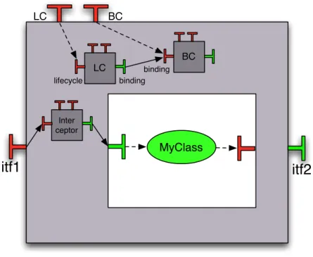
In Figures 20 and 21 there is respectively the graphical description of a primitive component containing an interceptor inside its membrane and the corresponding adl description. In Fig-ure 21, the membrane is described inside an inline controller system. Between lines 10 and 14, we can find the definition of an interceptor component. It is described in the same way as any component. In fact, I made the choice to make no distinction between a Nf component and an interceptor (one of the first ideas was to “tag” interceptors in such a way that only components tagged as interceptors could connect to functional interfaces). On line 7, we can see the refer-ence to the external functional interface of the component. On line 20, we connect the external interface to the interceptor and on line 21 we connect the interceptor to the internal functional
1 <?xml version="1.0" encoding="ISO-8859-1" ?>
2 <!DOCTYPE .... >
3
4 <definition name="org.objectweb.compositecomponent">
5 <interface name="itf1" role="server" signature="org.objectweb.MyInterface"
/>
6 <interface name="itf2" role="client" signature="org.objectweb.
MyClientInterface"/>
7 <content definition ="org.objectweb.MyCompositeContent"/ >
8 <controller desc="org.objectweb.MyCompositeMembrane"/>
9 </definition>
Figure 12: Description of a composite: content and membrane described in separate files
1 <?xml version="1.0" encoding="ISO-8859-1" ?>
2 <!DOCTYPE .... >
3
4 <definition name="org.objectweb.MyCompositeContent">
5
6 <interface name="itf1" role="client" signature="org.objectweb.MyInterface"
/>
7 <interface name="itf2" role="server" signature="org.objectweb.
MyClientInterface"/>
8 <component definition="org.objectweb.Foo" name="foo"/>
9 <component definition="org.objectweb.Bar" name="bar"/>
10 <binding client="this.itf1" server="foo.foo"/>
11 <binding client="foo.bar" server="bar.bar"/>
12 <binding client="bar.itf2" server="this.itf2"/>
13 </definition>
Figure 13:Content of the composite: separate file
interface. Notice that for primitive components the internal functional interface is not declared. For the binding between the interceptor and this interface, the internal interface is referenced by the name of the external one. Indeed, what matters in this case is the orientation of the binding. As we are binding a client interface of an interceptor to an interface with the name of an external one, we can be sure that we are binding the interceptor component to an internal interface.
4.2
Composite component
In Figures 22 and 23, we can see the graphical representation of a composite component with an interceptor inside its membrane with the corresponding adl representation. In the adl descrip-tion, we introduced only the noticeable changes in the Nf adl. the functional content remains the same(as in Figure13). The definition of the interceptor and the bindings between the interceptor and the functional interfaces are the same as in Figure 21. The internal interface is not declared, because we are using the name of the external interface to reference the corresponding internal one. Following the constraints on internal interfaces of composite components introduced in Section 2.4.2, the set of external and internal interfaces can be different. If an external interface has no corresponding internal interface, the internal interface has to be explicitely referenced.
5
DTD of the new adl
itf1
itf2
FOO BAR LC BC LC BC lifecycle binding binding foo bar bar CC CC contentFigure 14:Graphical representation of connexions between the content and the mem-brane of a composite component
1 <?xml version="1.0" encoding="ISO-8859-1" ?>
2 <!DOCTYPE .... >
3 <definition name="org.objectweb.MyCompositeContent">
4 <interface name="itf1" role="client" signature="org.objectweb.MyInterface"
/>
5 <interface name="itf2" role="server" signature="org.objectweb.
MyClientInterface"/>
6 <interface name="internal-lifecycle-controller" role="server" signature="
org.objectweb.MyLifecycleController"/>
7 ...
8 <binding client="foo.mylifecycle-controller" server=
"this.internal-lifecycle-controller"/>
9 </definition>
Figure 15:Bindings between the content and the membrane: the content file
1 <?xml version="1.0" encoding="ISO-8859-1" ?>
2 <!DOCTYPE .... >
3
4 <definition name="org.objectweb.MyCompositeMembrane" extends="org.
objectweb.NFType">
5 <interface name="mylifecycle-controller" role="internal-server" signature=
"org.objectweb.MyLifecycleController"/>
6 ...
7 <binding client="this.mylifecycle-controller" server="lifecycleController.
lifecycle"/>
8 </definition>
itf1
itf2
FOO BAR LC BC LC BC lifecycle binding binding foo bar bar CC CC contentFigure 17:Graphical representation of connexions between the membrane and the con-tent of a composite component
1 <?xml version="1.0" encoding="ISO-8859-1" ?>
2 <!DOCTYPE .... >
3 <definition name="org.objectweb.MyCompositeContent">
4 <interface name="itf1" role="client" signature="org.objectweb.MyInterface"
/>
5 <interface name="itf2" role="server" signature="org.objectweb.
MyClientInterface"/>
6 <interface name="internal-binding-controller" role="client" signature="org
.objectweb.MyBindingController"/>
7 ...
8 <binding client="this.internal-binding-controller" server=
"bar.binding-controller"/>
9 </definition>
Figure 18:Bindings between the membrane and the content: the content file
1 <?xml version="1.0" encoding="ISO-8859-1" ?>
2 <!DOCTYPE .... >
3
4 <definition name="org.objectweb.MyCompositeMembrane" extends="org.
objectweb.NFType">
5 <interface name="internal-binding-controller" role="internal-client"
signature="org.objectweb.MyBindingController"/>
6 ...
7 <binding client="bindingController.mybinding" server=
"this.internal-binding-controller"/>
8 </definition>
MyClass
LC BCitf1
itf2
LC BC Inter ceptor lifecycle binding bindingFigure 20: Graphical representation of a primitive component with componentized membrane containing interceptors
1 <?xml version="1.0" encoding="ISO-8859-1" ?>
2 <!DOCTYPE .... >
3 <definition name="org.objectweb.primitivecomponent" extends="org.objectweb
.Membrane">
4 <interface name="itf1" role="server" signature="org.objectweb.MyInterface"
/>
5 <content class="org.objectweb.MyClass"/>
6 <controller>
7 <interface name="itf1" role="server" signature="org.objectweb.
MyInterface"/>
8 <interface signature="org.objectweb.fractal.api.control.
BindingController" role="server" name="binding-controller
"/>
9 <interface signature="org.objectweb.fractal.api.control.
LifeCycleController"role="server" name=
"lifecycle-controller"/>
10 <component name="interceptor">
11 <interface signature="org.objectweb.Interceptor" role="
server-interceptor" name="serverIntercept"/>
12 <interface signature="org.objectweb.Interceptor" role="
client-interceptor" name="clientIntercept"/>
13 <content class="org.objectweb.InterceptorImpl"/>
14 </component>
15 <component definition="org.objectweb.proactive.core.component. componentcontroller.local.BindingControllerComponent"
name="bindingController"/>
16 <component definition="org.objectweb.proactive.core.component. componentcontroller.local.LifecycleControllerComponent"
name="lifecycleController"/>
17 <binding client="this.binding-controller" server="
bindingController.binding"/>
18 <binding client="this.lifecycle-controller" server="
lifecycleController.lifecycle"/>
19 <binding client="lifecycleController.binding" server="
bindingController.binding"/>
20 <binding client="this.itf1" server="interceptor.
serverIntercept"/>
21 <binding client="interceptor.serverIntercept" server="this.
itf1"/>
22 </controller>
23 </definition>
itf1
itf2
FOO BAR LC BC LC BC lifecycle binding binding foo bar bar Inter ceptor CC CC contentFigure 22: Graphical representation of a composite component with componentized membrane containing interceptors
1
2 <?xml version="1.0" encoding="ISO-8859-1" ?>
3 <!DOCTYPE .... >
4
5 <definition name="org.objectweb.MyCompositeMembrane" extends="org.
objectweb.NFType">
6
7 <interface name="itf1" role="server" signature="org.objectweb. MyInterface
"/>
8 ...
9 <component name="interceptor">
10 <interface signature="org.objectweb.Interceptor" role=
"server-interceptor" name="serverIntercept"/>
11 <interface signature="org.objectweb.Interceptor" role=
"client-interceptor" name="clientIntercept"/>
12 <content class="org.objectweb.InterceptorImpl"/>
13 </component>
14 ...
15 <binding client="this.itf1" server="interceptor.server-interceptor"/>
16 <binding client="interceptor.client-interceptor" server="this.itf1"/>
17 </definition>
1
2 <?xml version="1.0" encoding="ISO-8859-1" ?>
3
4 <!-- A DTD that includes all the "standard" Fractal ADL modules -->
5
6 <!-- ********************************************************************** -->
7 <!-- AST nodes definitions -->
8 <!-- ********************************************************************** -->
9
10 <?add ast="definition" itf="org.objectweb.fractal.adl.Definition" ?>
11
12 <!-- components module -->
13 <?add ast="component" itf="org.objectweb.fractal.adl.components.Component" ?>
14 <?add ast="definition" itf="org.objectweb.fractal.adl.components.ComponentDefinition" ?>
15
16 <!-- interfaces module -->
17 <?add ast="interface" itf="org.objectweb.fractal.adl.interfaces.Interface" ?>
18 <?add ast="definition" itf="org.objectweb.fractal.adl.interfaces.InterfaceContainer" ?>
19 <?add ast="component" itf="org.objectweb.fractal.adl.interfaces.InterfaceContainer" ?>
20
21 <!-- types module -->
22 <?add ast="interface" itf="org.objectweb.fractal.adl.types.TypeInterface" ?>
23
24 <!-- bindings module -->
25 <?add ast="binding" itf="org.objectweb.fractal.adl.bindings.Binding" ?>
26 <?add ast="definition" itf="org.objectweb.fractal.adl.bindings.BindingContainer" ?>
27 <?add ast="component" itf="org.objectweb.fractal.adl.bindings.BindingContainer" ?>
28
29 <!-- attributes module -->
30 <?add ast="attribute" itf="org.objectweb.fractal.adl.attributes.Attribute" ?>
31 <?add ast="attributes" itf="org.objectweb.fractal.adl.attributes.Attributes" ?>
32 <?add ast="definition" itf="org.objectweb.fractal.adl.attributes.AttributesContainer" ?>
33 <?add ast="component" itf="org.objectweb.fractal.adl.attributes.AttributesContainer" ?>
34
35 <!-- content module -->
36
37 <?add ast="component" itf="org.objectweb.fractal.adl.components.Component" ?>
38 <?add ast="definition" itf="org.objectweb.fractal.adl.components.ComponentDefinition" ?>
39
40 <!-- implementations module -->
41 <?add ast="implementation" itf="org.objectweb.fractal.adl.implementations.Implementation" ?>
42 <?add ast="definition" itf="org.objectweb.fractal.adl.implementations.ImplementationContainer"
?>
43 <?add ast="component" itf="org.objectweb.fractal.adl.implementations.ImplementationContainer"
?>
44 <?add ast="controller" itf="org.objectweb.fractal.adl.implementations.Controller" ?>
45 <?add ast="definition" itf="org.objectweb.fractal.adl.implementations.ControllerContainer" ?>
46 <?add ast="component" itf="org.objectweb.fractal.adl.implementations.ControllerContainer" ?>
47
48 <!-- loggers module -->
49 <?add ast="logger" itf="org.objectweb.fractal.adl.loggers.Logger" ?>
50 <?add ast="definition" itf="org.objectweb.fractal.adl.loggers.LoggerContainer" ?>
51 <?add ast="component" itf="org.objectweb.fractal.adl.loggers.LoggerContainer" ?>
52
53 <!-- nodes module -->
54 <?add ast="virtualNode" itf="org.objectweb.proactive.core.component.adl.nodes.VirtualNode" ?>
55 <?add ast="definition" itf="org.objectweb.fractal.adl.nodes.VirtualNodeContainer" ?>
56 <?add ast="component" itf="org.objectweb.fractal.adl.nodes.VirtualNodeContainer" ?>
57 58
59 <!-- arguments module -->
60 <?add ast="definition" itf="org.objectweb.fractal.adl.arguments.ArgumentDefinition" ?>
61
62 <!-- coordinates module -->
63 <?add ast="coordinates" itf="org.objectweb.fractal.adl.coordinates.Coordinates" ?>
64 <?add ast="definition" itf="org.objectweb.fractal.adl.coordinates.CoordinatesContainer" ?>
65 <?add ast="component" itf="org.objectweb.fractal.adl.coordinates.CoordinatesContainer" ?>
66
67 <!-- comments module -->
68 <?add ast="comment" itf="org.objectweb.fractal.adl.comments.Comment" ?>
69 <?add ast="definition" itf="org.objectweb.fractal.adl.comments.CommentContainer" ?>
70 <?add ast="component" itf="org.objectweb.fractal.adl.comments.CommentContainer" ?>
71 <?add ast="interface" itf="org.objectweb.fractal.adl.comments.CommentContainer" ?>
72 <?add ast="binding" itf="org.objectweb.fractal.adl.comments.CommentContainer" ?>
73 <?add ast="attributes" itf="org.objectweb.fractal.adl.comments.CommentContainer" ?>
74 <?add ast="attribute" itf="org.objectweb.fractal.adl.comments.CommentContainer" ?>
75 <?add ast="controller" itf="org.objectweb.fractal.adl.comments.CommentContainer" ?>
76 <?add ast="templateController" itf="org.objectweb.fractal.adl.comments.CommentContainer" ?>
77 <?add ast="implementation" itf="org.objectweb.fractal.adl.comments.CommentContainer" ?>
78 ...
1 ...
2 <!-- exported virtual nodes module -->
3 <?add ast="exportedVirtualNodes" itf="org.objectweb.proactive.core.component.adl.vnexportation
.ExportedVirtualNodes" ?>
4 <?add ast="exportedVirtualNode" itf="org.objectweb.proactive.core.component.adl.vnexportation.
ExportedVirtualNode" ?>
5 <?add ast="composedFrom" itf="org.objectweb.proactive.core.component.adl.vnexportation.
ComposedFrom" ?>
6 <?add ast="composingVirtualNode" itf="org.objectweb.proactive.core.component.adl.vnexportation
.ComposingVirtualNode" ?>
7
8 <?add ast="definition" itf="org.objectweb.proactive.core.component.adl.vnexportation.
ExportedVirtualNodesContainer" ?>
9 <?add ast="component" itf="org.objectweb.proactive.core.component.adl.vnexportation.
ExportedVirtualNodesContainer" ?>
10 <?add ast="exportedVirtualNodes" itf="org.objectweb.proactive.core.component.adl.vnexportation
.ExportedVirtualNodeContainer" ?>
11 <?add ast="exportedVirtualNode" itf="org.objectweb.proactive.core.component.adl.vnexportation.
ComposedFromContainer" ?>
12 <?add ast="composedFrom" itf="org.objectweb.proactive.core.component.adl.vnexportation.
ComposingVirtualNodeContainer" ?>
13 14
15 <?add ast="implementation" itf="org.objectweb.proactive.core.component.adl.content.Content" ?>
16 <?add ast="implementation" itf="org.objectweb.fractal.adl.interfaces.InterfaceContainer" ?>
17 <?add ast="implementation" itf="org.objectweb.fractal.adl.bindings.BindingContainer" ?>
18 <?add ast="implementation" itf="org.objectweb.fractal.adl.components.ComponentContainer" ?>
19 20
21 <?add ast="controller" itf="org.objectweb.fractal.adl.components.ComponentContainer" ?>
22 <?add ast="controller" itf="org.objectweb.fractal.adl.interfaces.InterfaceContainer" ?>
23 <?add ast="controller" itf="org.objectweb.fractal.adl.bindings.BindingContainer" ?>
24 25
26 <!-- ********************************************************************** -->
27 <!-- Mapping from XML names to AST names -->
28 <!-- ********************************************************************** -->
29
30 <?map xml="binding.client" ast="binding.from" ?>
31 <?map xml="binding.server" ast="binding.to" ?>
32
33 <?map xml="content" ast="implementation" ?>
34 <?map xml="content.class" ast="implementation.className" ?>
35
36 <?map xml="controller.desc" ast="controller.descriptor" ?>
37
38 <?map xml="virtual-node" ast="virtualNode"?>
39
40 <!-- ********************************************************************** -->
41 <!-- XML syntax definition -->
42 <!-- ********************************************************************** -->
43
44 <!ELEMENT definition (comment*,interface*,exportedVirtualNodes?, component*,binding*,content?, attributes?,controller?,logger?,virtual-node?,coordinates*) >
45 <!ATTLIST definition 46 name CDATA #REQUIRED 47 arguments CDATA #IMPLIED 48 extends CDATA #IMPLIED 49 >
50
51 <!ELEMENT component (comment*,interface*,exportedVirtualNodes?, component*,binding*,content?, attributes?,controller?,logger?,virtual-node?,coordinates*) >
52 <!ATTLIST component 53 name CDATA #REQUIRED 54 definition CDATA #IMPLIED 55 >
56
57 <!ELEMENT interface (comment*) >
58 <!ATTLIST interface 59 name CDATA #REQUIRED
60 role (client | server) #IMPLIED 61 signature CDATA #IMPLIED
62 contingency (mandatory | optional) #IMPLIED
63 cardinality (singleton | collection | multicast | gathercast) #IMPLIED 64 >
65
66 <!ELEMENT binding (comment*) >
67 <!ATTLIST binding 68 client CDATA #REQUIRED 69 server CDATA #REQUIRED 70 >
1 ...
2 <!ELEMENT attributes (comment*,attribute*) >
3 <!ATTLIST attributes
4 signature CDATA #IMPLIED 5 >
6
7 <!ELEMENT attribute (comment*) >
8 <!ATTLIST attribute
9 name CDATA #REQUIRED 10 value CDATA #REQUIRED 11 >
12
13 <!ELEMENT controller (comment*,interface*,component*,binding*) >
14 <!ATTLIST controller 15 desc CDATA #IMPLIED 16 >
17
18 <!ELEMENT content (comment*,interface*,component*,binding*) >
19 <!ATTLIST content 20 class CDATA #IMPLIED 21 definition CDATA #IMPLIED 22 >
23 24 25
26 <!ELEMENT logger EMPTY >
27 <!ATTLIST logger
28 name CDATA #REQUIRED 29 >
30
31 <!ELEMENT virtual-node EMPTY >
32 <!ATTLIST virtual-node 33 name CDATA #REQUIRED
34 cardinality (single | multiple) "single"
35 >
36
37 <!ELEMENT coordinates (coordinates*) >
38 <!ATTLIST coordinates
39 name CDATA #REQUIRED 40 x0 CDATA #REQUIRED 41 x1 CDATA #REQUIRED 42 y0 CDATA #REQUIRED 43 y1 CDATA #REQUIRED 44 color CDATA #IMPLIED 45 >
46
47 <!ELEMENT comment EMPTY >
48 <!ATTLIST comment
49 language CDATA #IMPLIED 50 text CDATA #IMPLIED 51 >
52
53 <!ELEMENT exportedVirtualNodes (exportedVirtualNode*) >
54 55
56 <!ELEMENT exportedVirtualNode (composedFrom) >
57 <!ATTLIST exportedVirtualNode 58 name CDATA #REQUIRED 59 >
60
61 <!ELEMENT composedFrom (composingVirtualNode+) >
62
63 <!ELEMENT composingVirtualNode EMPTY>
64 <!ATTLIST composingVirtualNode 65 component CDATA #REQUIRED 66 name CDATA #REQUIRED 67 >
Contents
1 Introduction 3
2 Development process and roles 3
2.1 The component architect . . . 3
2.2 The functional assembler . . . 4
2.3 The non-functional assembler . . . 4
2.4 Internal interfaces . . . 4
2.4.1 Primitive components . . . 5
2.4.2 Composite components . . . 5
3 Designing a membrane with components 5 3.1 Non-functional type . . . 5
3.2 Primitive component . . . 6
3.3 Composite component . . . 6
3.3.1 Connexions membrane-content and content-membrane . . . 8
4 Defining interceptors 9 4.1 Primitive component . . . 11
4.2 Composite component . . . 12
5 DTD of the new adl 12
References
[1] F. Baude, D. Caromel, L. Henrio, and P. Naoumenko. A flexible model and implementation of component controllers. In CoreGRID Workshop on Grid Programming Model, Grid and P2P Systems Architecture, Grid Systems, Tools and Environments, june 2007.
[2] C. Szyperski. Component Software: Beyond Object-Oriented Programming. Addison-Wesley Longman Publishing Co., Inc., Boston, MA, USA, 2002.
Centre de recherche INRIA Bordeaux – Sud Ouest : Domaine Universitaire - 351, cours de la Libération - 33405 Talence Cedex Centre de recherche INRIA Grenoble – Rhône-Alpes : 655, avenue de l’Europe - 38334 Montbonnot Saint-Ismier Centre de recherche INRIA Lille – Nord Europe : Parc Scientifique de la Haute Borne - 40, avenue Halley - 59650 Villeneuve d’Ascq
Centre de recherche INRIA Nancy – Grand Est : LORIA, Technopôle de Nancy-Brabois - Campus scientifique 615, rue du Jardin Botanique - BP 101 - 54602 Villers-lès-Nancy Cedex
Centre de recherche INRIA Paris – Rocquencourt : Domaine de Voluceau - Rocquencourt - BP 105 - 78153 Le Chesnay Cedex Centre de recherche INRIA Rennes – Bretagne Atlantique : IRISA, Campus universitaire de Beaulieu - 35042 Rennes Cedex Centre de recherche INRIA Saclay – Île-de-France : Parc Orsay Université - ZAC des Vignes : 4, rue Jacques Monod - 91893 Orsay Cedex
Éditeur
INRIA - Domaine de Voluceau - Rocquencourt, BP 105 - 78153 Le Chesnay Cedex (France)
http://www.inria.fr ISSN 0249-0803