HAL Id: tel-01751700
https://hal.univ-lorraine.fr/tel-01751700
Submitted on 29 Mar 2018HAL is a multi-disciplinary open access archive for the deposit and dissemination of sci-entific research documents, whether they are pub-lished or not. The documents may come from teaching and research institutions in France or abroad, or from public or private research centers.
L’archive ouverte pluridisciplinaire HAL, est destinée au dépôt et à la diffusion de documents scientifiques de niveau recherche, publiés ou non, émanant des établissements d’enseignement et de recherche français ou étrangers, des laboratoires publics ou privés.
containing ionic liquids for absorption heat transformers
El Shaimaa Talaat Yussef Abumandour
To cite this version:
El Shaimaa Talaat Yussef Abumandour. Study of environmentally friendly working mixtures contain-ing ionic liquids for absorption heat transformers. Food and Nutrition. Université de Lorraine, 2015. English. �NNT : 2015LORR0070�. �tel-01751700�
AVERTISSEMENT
Ce document est le fruit d'un long travail approuvé par le jury de
soutenance et mis à disposition de l'ensemble de la
communauté universitaire élargie.
Il est soumis à la propriété intellectuelle de l'auteur. Ceci
implique une obligation de citation et de référencement lors de
l’utilisation de ce document.
D'autre part, toute contrefaçon, plagiat, reproduction illicite
encourt une poursuite pénale.
Contact : [email protected]
LIENS
Code de la Propriété Intellectuelle. articles L 122. 4
Code de la Propriété Intellectuelle. articles L 335.2- L 335.10
http://www.cfcopies.com/V2/leg/leg_droi.php
UNIVERSITÉ DE LORRAINE
Ecole Doctorale RP2E : Ressources, Procédés, Produits, Environnement
Laboratoire Réactions et Génie des Procédés
– UMR 7274 CNRS – ENSIC
THÈSE
Présentée
El Shaimaa Talaat Yussef ABUMANDOUR
Pour l'obtention du grade de
Docteur en Science
de l’Université de Lorraine
Spécialité : Génie des Procédés et des Produits
Thèse soutenue publiquement le 2 Juillet 2015 devant la commission d’examen :
Rapporteurs:
Prof. Christophe COQUELET
Prof. Jean-Philippe PASSARELLO
Examinateurs :
Prof. Viviane RENAUDIN
Dr. Christophe NICOLAS
Dr. Fabrice MUTELET
Dr. Dominique ALONSO
STUDY OF ENVIRONMENTALLY FRIENDLY WORKING
MIXTURES CONTAINING IONIC LIQUIDS FOR
ACKNOWLEDGMENTS
First of all, I am grateful to Almighty God for giving me the strength to fulfill this work. I would like to express my sincere gratitude to my Supervisor, Dr. Fabrice MUTELET. I am
thankful for his support, aspiring guidance, invaluably constructive criticism and friendly advices during my PhD. I am sincerely grateful to him for sharing his truthful and
illuminating views on a number of issues related to the study.
I would like to express my deepest gratitude to my Co-advisor, Dr. Dominique ALONSO, for his excellent guidance, caring, patience, and providing me with excellent ideas, explanations and suggestions throughout my study. I am extremely grateful for his assistance
and support. I owe you an enormous debt of gratitude for your help, time and consideration. I attribute the level of my PhD degree to Fabrice and Dominique encouragement and effort
without them this thesis, would not have been completed or written. The enjoyment and passion they have for scientific research was infectious and motivational for me, even during
tough periods in the Ph.D. quest. One simply could not wish for a better or friendlier supervision.
I would like to thank the Université de Lorraine and Erasmus mundus for giving me the opportunity to fulfill my PhD.
A very special thanks goes out to Laboratoire Réactions et Génie des Procédés (LRGP-UMR 7274 CNRS) in Nancy, where this work was accomplished. I would first like to thank Mr.
Gabriel WILD, (former director of LRGP) and Laurent FALK (current director), for hosting me in this laboratory.
I would also like to thank Mr. Mohamed Bourokba for his help and precious conversations. Special thanks and gratitude goes to Prof. Christophe COQUELET and Prof Jean-Philippe
PASSARELLO for accepting the task of judging this work. I assure my deep gratitude to Prof. Viviane RENAUDIN and Dr. Christophe NICOLAS. Their presence in the jury
honors me.
I would like to express my appreciation to all the staff members of ThermE: Jean-Noël JAUBERT (Responsible of the team), Jean-Charles MOÏSE, Romain PRIVAT, Michel
DIRAND, Nathalie HUBERT and Roland SOLIMANDO. I would like to thank Mr. Patrick carre for his availability and help.
Additionally, I would also like to thank all my colleagues who have made these three years an enjoyable and rewarding experience: El Sayed R. HASSAN, Armel GONDA, Niramol JUNTARACHAT, Imane HADDADOU, Amal AYAD, Chen YUSHU, Zehor BENSAID, Afef ATTIA, Lais TEDESCO, Mohamed ALJUBURY, Joël MALLICK, Vincent PLEE,
Laëtitia CESARI and Silvia LASALA.
Most of all, I am fully indebted to my “Mother”, my elder Sister and my younger Brothers for their unconditional love, understating, wisdom, patience, encouragement and for pushing
i
Table of contents
Nomenclature and symbols ... xi
Résumé ... 1
INTRODUCTION ... 9
CHAPTER ONE: STATE OF THE ART ... 13
I.1. Introduction ... 13
I.2. Ionic Liquids ... 13
I.3. History and progress of ionic liquids ... 15
I.4. Classes of ionic liquids ... 17
I.5. Physico-chemical properties of Ionic liquids ... 18
I.5.1. vapor pressure ... 18
I.5.2. Activity coefficient for ionic liquids ... 18
I.5.3. Density ... 20
I.5.4. Viscosity ... 20
I.5.5. Surface tension ... 21
I.5.6. Miscibility with water ... 21
I.5.7. Melting point ... 22
I.5.8. Thermal stability ... 23
I.5.9. Flammability and corrosion ... 24
I.5.10. Toxicity and human health ... 25
I.6. Potential Applications of Ionic Liquids ... 26
I.7. General information about Absorption cycles ... 32
I.8. Classification of Absorption cycles ... 34
I.8.1. Absorption refrigerators (Chillers) (AC) ... 37
I.8.2. Absorption heat pumps (AHP) ... 37
ii
I.9. Working fluids containing {water + ILs} for absorption cycles ... 39
I.9.1. {H2O + Ionic liquids} binary systems in literature ... 39
I.10. Thermodynamic properties of {H2O + IL} ... 41
I.10.1. Thermodynamic model for the representation of binary system {H2O + IL} .. 41
I.10.2. Experimental thermodynamic data of {H2O + IL} ... 43
I.10.2.1. Vapor liquid equilibrium (VLE) ... 43
I.10.2.2. Heat capacity ... 48
I.10.2.3. Excess Enthalpy (HE) ... 50
I.10.2.4. Density... 52
I.10.2.5. Viscosity ... 57
I.10.2.6. Thermal decomposition ... 58
References ... 60
CHAPTER TWO: THERMODYNAMIC OF BINARY SYSTEMS COMPOSED OF {WATER + IONIC LIQUID} ... 69
II.1. Experimental section ... 69
II.1.1. Materials ... 69
II.1.2. Vapor Liquid Equilibrium (VLE) ... 70
II.1.2.1. Isobaric VLE apparatus ... 72
II.1.2.2. Isothermal VLE measurement ... 73
II.1.3. Heat capacity (Cp) ... 75
II.1.4. Density (ρ) ... 76
II.1.5. Excess enthalpy (HE) ... .78
II.2. Results and discussion ... 80
II.2.1. Vapor Liquid Equilibrium (VLE) ... 80
iii
II.2.3. Density (ρ) ... 97
II.2.3.1. Excess molar volume VE ... 101
II.2.4. Excess molar Enthalpy (HE) ... 106
References ... 110
CHAPTER THREE: PERFORMANCE SIMULATION (COP) ... 115
III.1. Simulation of the AHT cycle performance ... 118
III.2. COP definition for an Absorption refrigeration cycle ... 124
III.3.Absorption heat transformer ... 125
References ... 139
CONCLUSIONS AND PERSPECTIVES ... 141
References ... 144
iv
List of Tables
Tableau 1: Liquides ioniques étudiés 5
Table I.1: Common ILs cations and anions 14
Table I.2: Melting point data for different ionic liquids [6, 7] 23
Table I.3: LC50 values for certain solvents [34] 26
Table I.4: Overview of industrial applications of ILs (Commercial/pilot plants) [6, 7] 31
Table I.5: NRTL parameters of binary systems {H2O + ILs} 47
Table I.6: Mass heat capacity parameters of binary systems {H2O + ILs} 49
Table I.7: Excess enthalpy HE parameters of binary systems {H
2O (1) + ILs (2)} 51
Table I.8: Density parameters of binary systems {H2O (1)+ ILs (2)} 53
Table I.9: Decomposition temperature for miscible Ils 59
Table II.1: Physical properties of studied ionic liquids 71
Table II.2: Comparison of the saturated vapor pressure of pure water (P exp.) measured in this
work and those published (P lit.) in the literature [11] 80
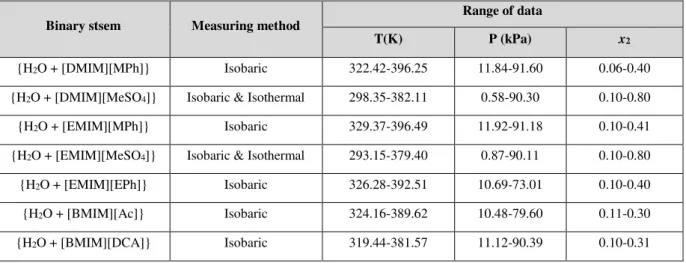
Table II.3: Summary of VLE measurements for the studied binary systems {H2O (1) + ILs (2)}
81
Table II.4: NRTL parameters of the VLE data for {H2O (1) + IL (2)} 85
Table II.5: Mass heat capacity comparison of ultrapure water [4] 90
Table II.6: Parameters for the correlation of Eq. (II.11) 91
Table II.7: Parameters for the correlation of Eq. (II.13) 92
Table II.8: Parameters for the correlation of Eq. (II.15) 97
Table II.9: Redlich Kister parameters for VE for {H
2O (1) + ILs (2)} binary systems 103
Table II.10: Redlish-kister parameters for HE for {H
2O (1) + ILs (2)} 108
Table III.1: Binary systems investigated in this work and their Thermodynamic properties 116 Table III.2: COP of {H2O + absorbent} binary systems for absorption refrigeration cycle found
v
Table III.3: Calculated COP of {H2O + ILs} binary systems for absorption heat transformer
cycle compared to data found in literature*,** 128
Table III.4: The available heat output per unit mass of refrigerant (q) for AHT cycle
vi
List of Figures
Figure 1: Cations des liquides ioniques 3
Figure 2: Influence de la structure du liquide ionique sur le coefficient de performance 6 Figure I.1: Growth rate of ionic liquid publications, 1999-2013 [SciFinder, 2014] 17
Figure I.2: Commonly used anions and their miscibility with water 22
Figure I.3: Ignition test of 1 g of protonated [1-Bu-3H-IM][NO3] [26] 24
Figure I.4: Possible applications of ILs 27
Figure I.5: The BASILTM process [16] 28
Figure I.6: Process scheme integrating Dimersol and Difasol [16] 29
Figure I.7: A spray nozzle for aqueous solutions of sodium chloride (left) and a hydrophilic
ionic liquid (right), each after 10 h of operation (©IoLiTec 2007) [16] 30
Figure I.8: Absorption cycles 35
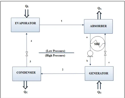
Figure I.9: Schematic diagram of an absorption refrigeration cycle; A-absorber, C-condenser,
E-evaporator, G-generator, SHE-heat exchanger 36
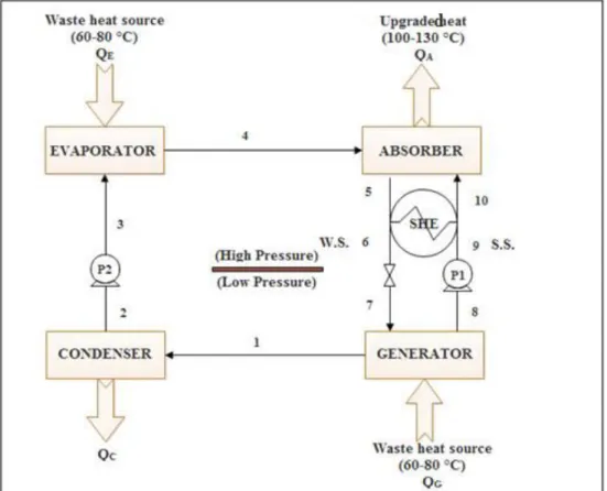
Figure I.10: Schematic diagram of an absorption heat transformer; A-absorber, C-condenser,
E-evaporator, G-generator, SHE-heat exchanger, P1, P2-pump, v-valve 38
Figure I.11: Water activity coefficients, γw, as function of the water mole fraction in binary
solutions of {water (1) + IL (2)}: (a) [BMIM][Br], [BMIM][C1SO3], [BMIM][SCN];
(b) }: [EMIM][(CF3SO2)2N], [BMIM][(CF3SO2)2N], [EMIM][BF4] 45
Figure I.12: Excess enthalpy, HE for the binary mixtures {water (1) + ionic liquid (2)} at T =
298.15 K. Ionic liquids [EMIM][EtSO4], [BMIM][MeSO4], [EMIM][Triflate],
[BMIM][Triflate], [BMPy][BF4] [84] 51
Figure I.13: Excess molar volumes, VE for the binary mixtures {water (1) + ionic liquid (2)}
at T = 298.15 K. Ionic liquids: (a) [BMIM][DCA], [EEPy][EtSO4], [BMIM][TFO]; (b)
[BMPy][DCA], [BMPyr][TFO], [BMPy][TFO]; (c) [HMIM][DCA],
[MPy][MeSO4] [87] 56
Figure I.14: Viscosity for the binary mixtures {water (1) + [EMIM][DMP] (2)} at different temperatures and mole fractions of IL x2 = 0.2; x2 = 0.4; x2 = 0.6; x2 = 0.8; x2 = 1
with solid lines to guide the eye [60] 58
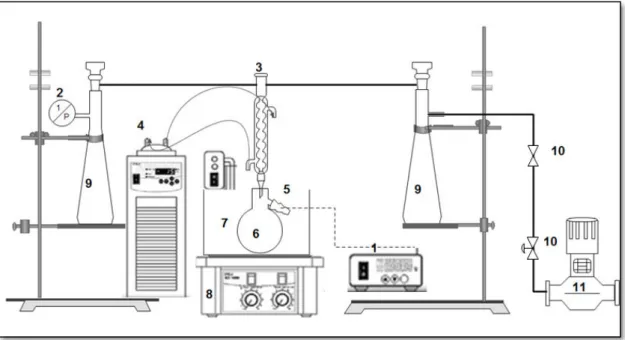
Figure II.1: Schematic diagram of isobaric VLE apparatus. 1. Temperature transmitter; 2. Pressure transducer (Druck-PMP4010); 3. Condenser; 4. Refrigerator; 5. Temperature sensor (T900 series); 6. Equilibrium vessel; 7. Thermostatic bath; 8. Magnetic stirrer; 9. Pressure
vii
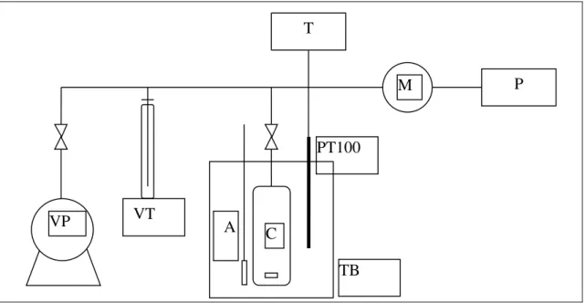
Figure II.2: Schematic representation of the VLE apparatus: VP: Vacuum Pump; VT: Vacuum
Trap; A: Magnetic Stirrer; C: Equilibrium Cell; PT: Platinum resistance Thermometer (PT-100); T: Temperature Indicator; M: Calibrated Pressure Sensor, P: Digital Pressure Indicator
and TB: Thermostatic Bath 74
Figure II.3: Setaram microDSCIII Calorimeter 75
Figure II.4: MicroDSC III Hastelloy pans 75
Figure II.5: DMA 512P measuring vibrating cell [7] 77
Figure II.6: Schematic diagram of C80 reversal mixing cell. 1. body of the stacked cell .2. vessel stopper .3. stainless steel stopper .4. Teflon O-ring .5. lid .6. Teflon O-ring .7. bottom
chamber .8. bottom compartments of the cell 79
Figure II.7: Experimental � values for the binary systems {H2O (1) + ILs (2)} as a function
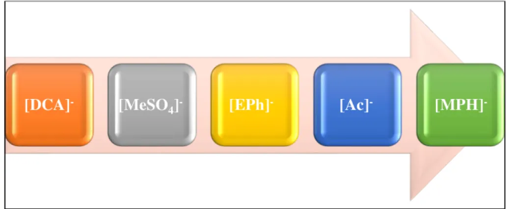
of mole fraction of water ( ) [DMIM][MPh]; ( ) [EMIM][MPh]; ( ) [EMIM][EPh]; ( ) [DMIM][MeSO4]; ( ) [BMIM][DCA]; —, calculated by NRTL equation 82 Figure II.8: The reduction trend of the activity coefficients and vapor pressure with respect to
the anion type 83
Figure II.9: Experimental VLE data for the investigated binary systems {H2O (1) + IL (2)} symbols are experimental data for different mole fractions of ILs and —, calculated by NRTL equation: (a) [DMIM][MPh] ( ) x2 =0.1; ( ) x2=0.19; ( ) x2=0.3; ( ) x2=0.4, (b) [EMIM][MPh]
( ) x2 =0.1; ( ) x2=0.2; ( ) x2=0.29; ( ) x2=0.4, (c) [EMIM][EPh] : ( ) x2 =0.1; ( ) x2=0.23; (
) x2=0.31; ( ) x2=0.4 86
Figure II.10: Experimental VLE data for the investigated binary systems {H2O (1) + [DMIM][MeSO4] (2)}: (a) Isobaric VLE data symbols are experimental data at different mole
fractions of [DMIM][MeSO4]: ( ) x2 =0.1; ( ) x2=0.2; ( ) x2=0.25; —, calculated by NRTL
equation, (b) Isothermal VLE for: ( ) T= 298.15 K; ( ) T= 303.15 K; ( ) T= 308.15 K; ( )
T= 313.15 K; ( ) T= 318.15 K; —, calculated by NRTL 87
Figure II.11: Experimental VLE data for the investigated binary systems {H2O (1) + [EMIM][MeSO4] (2)}: (a) symbols are experimental data for different mole fractions of
[EMIM][MeSO4]: ( ) x2 =0.15; ( ) x2=0.25; ( ) x2=0.35; —, calculated by NRTL equation,
(b) Isothermal VLE for: ( ) T= 293.15 K; ( ) T= 298.15 K; ( ) T= 303.15; ( ) T= 308.15; (
) T= 313.15K; —, calculated by NRTL 88
Figure II.12: Experimental VLE data for the investigated binary systems {H2O (1) + IL (2)} symbols are experimental data at different mole fractions of ILs and —, calculated by NRTL equation: (a) [BMIM][DCA]: ( ) x2=0.1; ( ) x2=0.2; ( ) x2 =0.3, (b) [BMIM][Ac]: ( ) x2=0.1;
viii
Figure II.13: Heat capacities of {H2O (1) + ILs (2)} versus temperature at different mole fractions of IL: (a) {H2O (1) + [EMIM][EPh] (2)} ( ) x2=1; ( ) x2=0.1; ( ) x2=0.2; ( ) x2=0.3;
( ) x2=0.48; ( ) x2=0.87;—, calculated by polynomial equation (II.11) 92 Figure II.14: Heat capacities of {H2O (1) + ILs (2)} versus temperature at different mole fractions of IL: (a) {H2O (1) + [DMIM][MeSO4] (2)} ( ) x2=1; ( ) x2=0.1; ( ) x2=0.2; ( )
x2=0.3; ( ) x2=0.4; ( ) x2=0.5 ; ( ) x2=0.6; ( ) x2=0.7, (b) {H2O (1) + [EMIM][MeSO4] (2)}
( ) x2=1; ( ) x2=0.1; ( ) x2=0.2; ( ) x2=0.3; ( ) x2=0.4; ( ) x2=0.5 ; ( ) x2=0.6; ( ) x2=0.8;
—, calculated by polynomial equation (II.11) 93
Figure II.15: Heat capacities of {H2O (1) + [BMIM][DCA] (2)} versus temperature at different mole fractions of the IL: ( ) x2=1; ( ) x2=0.1; ( ) x2=0.2; ( ) x2=0.3; ( ) x2=0.4; ( ) x2=0.5
; ( ) x2=0.6; ( ) x2=0.7; ( ) x2=0.86; —, calculated by polynomial equation (II.11)
94
Figure II.16: Excess heat capacities of {H2O (1) + ILs (2)} versus x2 of the IL at different
temperatures: (a) {H2O (1) + [EMIM][EPh] (2)} ( ) T=301.15K; ( ) T=303.15K; ( )
T=321.15K; —, calculated by Redlich–Kister equation 94
Figure II.17: Excess heat capacities of {H2O (1) + ILs (2)} versus x2 of the IL at different
temperatures: (a) {H2O (1) + [DMIM][MeSO4] (2)} ( ) T=301.15K; ( ) T=318.15K; ( )
T=337.15K, (b) {H2O (1) + [EMIM][MeSO4] (2)} ( ) T=301.15K; ( ) T=318.15K; ( )
T=337.15K; —, calculated by Redlich–Kister equation 95
Figure II.18: Excess heat capacities of {H2O (1) + [BMIM][DCA] (2)} versus x2 of the IL at
different temperatures: ( ) T=301.15K; ( ) T=303.15K; ( ) T=321.15K;—, calculated by
Redlich–Kister equation 96
Figure II.19: Trend of density of the investigated binary systems ( ) [DMIM][MPh]; ( )[EMIM][MPh]; ( ) [EMIM][EPh]; ( ) [BMIM][DCA]; ( ) [DMIM][MeSO4]; ( )
[EMIM][MeSO4] ; —, calculated by polynomial equation (II.15) 98
Figure II.20: Density of {H2O (1) + IL (2)} versus temperature at different molar fractions of IL: (a) {H2O (1) + [DMIM][MPh] (2)} ( ) x2=1; ( ) x2=0.1; ( ) x2=0.2; ( ) x2=0.3; ( )
x2=0.4; ( ) x2=0.5, (b) {H2O (1) + [EMIM][MPh] (2)} ( ) x2=1; ( ) x2=0.1; ( ) x2=0.2; ( )
x2=0.3, (c) {H2O (1) + [EMIM][EPh] (2)} ( ) x2=1; ( ) x2=0.1; ( ) x2=0.2; ( ) x2=0.3; —,
calculated by polynomial equation (II.15) 99
Figure II.21: Density of {H2O (1) + IL (2)} versus temperature at different molar fractions of IL: (a) {H2O (1) + [DMIM][MeSO4] (2)} ( ) x2=1; ( ) x2=0.1; ( ) x2=0.2; ( ) x2=0.3; ( )
ix
) x2=0.2; ( ) x2=0.3; ( ) x2=0.4; ( ) x2=0.5; ( ) x2=0.6; ( ) x2=0.7;—, calculated by
polynomial equation (II.15) 100
Figure II.22: Density of {H2O (1) + [BMIM][DCA] (2)} versus temperature at different molar fractions of [BMIM][DCA]: ( ) x2=1; ( ) x2=0.1; ( ) x2=0.3; ( ) x2=0.5; ( ) x2=0.7; —,
calculated by polynomial equation (II.15) 101
Figure II.23: Experimental excess molar volume, VE against mole fraction of IL at different
temperatures, (a) [DMIM][MPh]T: ( ) T=293.15 K; ( ) T = 303.15 K; ( ) T = 313.15 K; ( ) T = 313.15 K, (b) [EMIM][MPh] T: ( ) T=293.15 K; ( ) T = 303.15 K; ( ) T = 313.15 K; ( ) T = 313.15 K, (c) [EMIM][EPh] T: ( ) T=293.15 K; ( ) T = 303.15 K; ( ) T = 313.15 K; (
) T = 313.15 K; —, correlated by Redlich-kister equation 104
Figure II.24: Experimental excess molar volume, VE against mole fraction of IL at different
temperatures, (a) [DMIM][MeSO4] T: ( ) T=293.15 K; ( ) T = 313.15 K; ( ) T = 323.15 K,
(b) [EMIM][MeSO4] T: ( ) T=293.15 K; ( ) T = 303.15 K; ( ) T = 313.15 K; ( ) T = 323.15
K; —, correlated by Redlich-kister equation 105
Figure II.25: Experimental excess molar volume, VE against mole fraction of [BMIM][DCA]
at different temperature T: ( ) T=293.15 K;( ) T = 303.15 K; ( ) T = 313.15 K; ( ) T = 323.15
K;—, correlated by Redlich-kister equation 106
Figure II.26: Experimental excess molar enthalpy, HE against different mole fraction x 2 of: (
) [DMIM][MPh], ( ) [EMIM][MPh], (b) ( ) [DMIM][MeSO4], ( ) [EMIM][MeSO4] at
312.92 K (b) ; —, correlated by Redlich-kister equation 107
Figure II.27: Experimental excess molar enthalpy, HE against different mole fraction x 2 of: (
) [DMIM][MeSO4], ( ) [DMIM][MPh] at 312.92 K; —, correlated by Redlich-kister equation
109
Figure II.28: Experimental excess molar enthalpy, HE against different mole fraction x 2 of: (
) [EMIM][MPh], ( ) [EMIM][EPh], ( ) [EMIM][MeSO4] at 312.92 K (b) ; —, correlated by
Redlich-kister equation 109
Figure III.1: Schematic diagram of an absorption heat transformer; TM-medium temperature,
TL-lowtemperature, TH-high temperature, SHE-solution heat exchanger 118
Figure III.2: Thermodynamic cycle in absorption heat transformer (AHT) 126
Figure III.3: Flow chart for COP simulation 127
Figure III.4: COP of binary systems {water + ILs} versus TL for single effect absorption heat
transformer cycle 131
Figure III.5: COP of binary systems {water + ILs} versus TM for single effect absorption heat
x
Figure III.6: COP of binary systems {water + ILs} versus TH for single effect absorption heat
transformer cycle 134
Figure III.7: Effect of TH on (xmw) weak solution concentration 135
Figure III.8: Simulation trend for the investigated binary systems Group I ( ) and II ( )
xi
Nomenclature and symbols
Abbreviations
AHP Absorption heat pump
AHT Absorption heat transformers
AC Absorption chillers (refrigeration)
ARD Average relative deviation
COP Coefficient of performance
COSMO-RS Conductor like screening model for real solvents
CHF3 Fluoroform
E181 Tetraethylene glycol dimethyl ether
EOS Equation of state
f Circulation ratio
GWP Global warming potential
HFCs Hydroflorocarbons
IL Ionic liquids
LLE Liquid-liquid equilibrium (T (K), P (kPa))
NRTL Nonrandom two-liquid model
ODP Ozone depletion potential
xii
TGA Thermogravimetric analysis
TFE 2, 2, 2-trifluoroethanol
UNIQAC Universal quasi chemical model
UNIFAC Universal functional activity coefficient
VLE Vapor liquid equilibrium (T (K), P (kPa))
VLLE Vapor-liquid-liquid equilibrium (T (K), P (kPa))
Symbols
Ai and Bi Adjustable parameters
ai and bi Adjustable parameters
Cp Molar heat capacity (J.mol-1.K-1)
CpE Molar excess heat capacity (J.mol-1.K-1)
gij Energy of interactionbetween species i and j
hi Enthalpy of stream (i =1, 2, ...,10) (kJ.kg-1)
HE Molar excess enthalpy (J.mol-1)
Δmixh Mixing enthalpy of the system (kJ kg-1)
i =1 Water (refrigerant)
i= 2 Ionic liquids (absorbent)
̇ Mass flow rate of stream (i = 1, 2…. 10) (kg.s-1)
p System pressure (kPa)
xiii
Q Heat load (kJ.s-1)
TH, TM, TL High, moderate and low temperature level (K, °C)
TC, TE, TG,TA Condenser, Evaporator, Generator and Absorber temperatures(K, °C)
T System temperature (K)
∆t Gross temperature lift (K, °C)
VE Excess molar volum (cm3. mol-1)
x Mass fraction of species i where i = 1,2
xm
s Mass fraction of ILs in the strong solution
xm
w Mass fraction of ILs in the weak solution
x Mole fraction
∆xm Difference of mass fraction between strong and weak solutions
Subscripts
A Absorber
C Condenser
E Evaporator
G Generator
SHE Solution heat exchanger
ss Strong solution
xiv
Greek leters
� Non-random parameter of NRTL model
Density (g.cm-3)
� Activity coefficient of species i (dimensionless), i =1, 2, (1 = refrigerant,
2 = absorbant)
Ionic liquids
[DMIM][Cl] 1,3-dimethylimidazolium chloride
[DMIM][MPh] 1,3-dimethylimidazolium methyl-phosphonate [DMIM][BF4] 1,3-dimethylimidazolium tetrafluoroborate
[DMIM][DMP] 1,3-dimethylimidazolium dimethylphosphate [HOEtMIM][Cl] 1-(2-hydroxyethyl)-3-methylimidazolium chloride
[HOEtMIM][BF4] 1-(2-hydroxyethyl)-3-methylimidazolium tetrafluoroborate
[HOEtMIM][TFA] 1-(2-hydroxyethyl)-3-methylimidazolium trifluoroacetate [EMIM][BF4] 1-ethyl-3-methylimidazolium tetrafluoroborate
[EMIM][DMP] 1-ethyl-3-methylimidazolium dimethylphosphate [EMIM][I] 1-ethyl-3-methylimidazolium iodide
[EMIM][Tf2N] or [(CF3SO2)2N] 1-ethyl-3-methylimidazolium bis-(trifluoromethyl
sulfonyl) imide
[EMIM][Ac] 1-ethyl-3-methylimidazolium acetate
[EMIM][HSO4] 1-ethyl-3-methylimidazolium hydrogen sulfate
[EMIM][EtSO4] 1-ethyl-3-methylimidazolium ethyl sulfate
xv
[EMIM][TFO] or [Triflate] 1-ethyl-3-methylimidazolium trifluoromethane sulfonate [EMIM][TFA] 1-ethyl-3-methylimidazolium trifluoroacetat
[EMIM][SCN] 1-ethyl-3-methylimidazolium thiocyanate
[EMIM][MeSO3] 1-ethyl-3-methylimidazolium methanesulfonate
[EMIM][TOS] 1-ethyl-3-methylimidazolium tosylate
[BMIM][DMP]1-butyl-3-methylimidazolium dimethylphosphate [BMIM][BF4] 1-butyl-3-methylimidazolium tetrafluoroborate
[BMIM][CF3SO3] or [TFO] or [triflate] 1-butyl-3-methylimidazolium trifluoromethane
sulfonate
[BMIM][C1SO3] 1-butyl-3-methylimidazolium methane sulfonate
[BMIM][Cl]1-butyl-3-methylimidazolium chloride [BMIM][Br] 1-butyl-3-methylimidazolium bromide [BMIM][Ac] 1-butyl-3-methylimidazolium acetate
[BMIM][CF3CO2] 1-butyl-3-methylimidazolium trifluoroacetate
[BMIM][I] 1-butyl-3-methylimidazolium iodide
[BMIM][SCN] 1-butyl-3-methylimidazolium thiocyanate [BMIM][TOS] 1-butyl-3-methylimidazolium tosylate
[BMIM][N(CN)2] 1-butyl-3-methylimidazolium dicyanamide
[BMIM][C(CN)3] 1-butyl-3-methylimidazolium tricyanomethane
[BMIM][Tf2N] 1-butyl-3-methylimidazolium bis(trifluoromethylsulfonyl)imide
[BMIM][MeSO4] 1-butyl-3-methylimidazoliumMethylsulfate
[HMIM][BF4]1-hexyl-3-methylimidazolium tetrafluoroborate
[HMIM][DCA] 1-hexyl-3-methylimidazolium dicyanamide [BDMIM][BF4] 1-butyl-2,3-dimethylimidazolium tetrafluoroborat
xvi
[EEIM][DEP] 1-ethyl-3-ethylimidazolium diethyl phosphate [DEMA][OMs] diethylmethylammonium methane sulfonate [BMPYR][DCA]1-butyl-1-methylpyrrolidinium dicyanamide
[BMPy][TFO] 1-butyl-3-methylpyridinium trifluoromethanesulfonate [BMPyr][TFO]1-butyl-1- methylpyrrolidinium trifluoromethanesulfonate [BMPIP][DCA] 1-butyl-1 -methylpiperidinium dicyanamide
[BMPy][BF4] 1-butyl-3-methylpyridinium tetrafluoroborat
[BPy][BF4] N-butyl-pyridinium tetrafluoroborate
[BPy][PF6] N-butyl-pyridinium hexafluorophosphate
[BPy][Ac] N-butyl-pyridinium acetate [BPy][Br] N-butyl-pyridinium bromide [Choline][MeSO3] choline methanesulfonate
[Choline][Gly] choline glycolate [Choline][Lac] choline lactate
[EEPy][EtSO4] 1,2- diethylpyridinium ethylsulfate
[MPy][MeSO4] 1-methylpyridinium methylsulfate
[P66614][Br] trihexyl(tetradecyl)phosphonium bromide
[C6iQuin][SCN] 1-hexylisoquinolinium thiocyanate [C8iQuin][SCN] 1-octylisoquinolinium thiocyanate
1
Résumé
Ces dernières années, les activités domestiques et industrielles ont entraîné un besoin croissant en ressources fossiles alors que les réserves mondiales s’épuisent. De plus, les problèmes environnementaux liés à l'effet de serre deviennent prégnants. Par conséquent, l'efficacité énergétique, la conservation et le développement de sources d'énergie alternatives comme l'énergie solaire connaissent un intérêt croissant. À l'heure actuelle, la communauté scientifique s’intéresse au développement d'équipements qui facilitent la récupération et l'utilisation rationnelle de l'énergie. Ainsi, la réutilisation des flux thermiques des chaleurs résiduaires provenant des activités industrielles, telles que les centrales électriques, constitue une alternative prometteuse. En effet, d'énormes quantités de chaleur à basse température (de 60 à 100°C) sont libérées dans l'atmosphère par de nombreuses installations [1].
Les pompes à chaleur à absorption sont particulièrement appropriées pour utiliser les chaleurs fatales. Elles peuvent être utilisées aussi bien pour le chauffage que pour le refroidissement (air conditionné ou la réfrigération). De plus, il est possible de produire de la chaleur à haute température (120 - 150°C) à partir d’une source de chaleur à température moyenne (typiquement 60 - 80°C) en utilisant un type particulier de pompe à chaleur à absorption : le thermo-transformateur de chaleur à absorption.
Malheureusement, des limitations techniques empêchent un plus grand développement de cette technologie. Le mélange de travail utilisé dans le cycle est généralement constitué d'eau et de bromure de lithium et impose l’utilisation de matériaux spécifiques afin d’éviter tout problème de corrosion. L’éventuelle cristallisation du bromure de lithium limite aussi les conditions de fonctionnement. Le mélange eau/ammoniac peut aussi être utilisé, mais exige de travailler sous haute pression. Ce système est toxique et peu respectueux de l'environnement. La volatilité relative de ce mélange significativement supérieure à l’unité implique la présence d’une étape de rectification dans le cycle réduisant ainsi l'efficacité énergique du procédé.
La recherche de mélanges de travail alternatifs pour les pompes à chaleur à absorption a connu de nombreux développement ces dernières décennies. L’utilisation de mélanges binaires constitués d’un liquide ionique et d’un solvant semble être prometteuse en remplacement des fluides de travail conventionnels ({H2O + LiBr} ou {NH3 + H2O}) [2-5].
2
I/ Cycles à absorption
Les cycles à absorption ont été développés au cours du XIXème siècle et ont reçu une attention
importante ces dernières décennies. Parmi les technologies récentes, on trouve les réfrigérateurs à absorption ou refroidisseurs, les pompes à chaleur à absorption et les thermo-transformateurs de chaleur à absorption. Les cycles à absorption permettent l’échange de chaleur avec au minimum trois sources à trois niveaux de température différents : faible, intermédiaire et élevé. Quand un système à absorption est exploité comme un réfrigérateur ou une pompe à chaleur, la chaleur motrice provient de la source haute température. Dans le cas du réfrigérateur, le froid utile est produit à un niveau de température faible et de la chaleur est rejetée à un niveau de température intermédiaire. L’environnement est ainsi utilisé en tant que réservoir à température intermédiaire. Dans le cas de la pompe à chaleur, la chaleur utile produite est à un niveau de température intermédiaire et l’environnement est alors utilisé comme un réservoir à basse température. Le thermo-transformateur de chaleur à absorption reçoit quant à lui une chaleur issue d’un réservoir à température intermédiaire et rejette de la chaleur à un niveau de température faible (l'environnement). La sortie utile est obtenue à un niveau de température plus élevé.
Malgré leur intérêt évident, les thermo-transformateurs de chaleur à absorption sont rarement utilisés dans la pratique car leurs performances restent faibles (seulement 30 à 50% de la chaleur résiduaire est revalorisée). De plus, il existe des limitations techniques liées à la corrosion et au risque de cristallisation, notamment lorsque le mélange {H2O + LiBr} est utilisé [6-7].
Qu'il s'agisse de réfrigérateur, de pompe à chaleur ou de thermo-transformateur, le mélange de travail est constitué d’un composé léger : le réfrigérant (l’eau dans cette étude) et d’un composé moins volatil : l’absorbant (un liquide ionique dans cette étude). Le cycle à absorption est schématiquement réalisé par l’association d’une étape de séparation et d’une étape de mélange réalisées à différentes pressions. On compte cinq composants principaux dans ce cycle : l’évaporateur, le condenseur, le générateur (ou désorbeur), l'absorbeur ainsi que l’échangeur de chaleur (ou économiseur).
II/ Les liquides ioniques
Les liquides ioniques (LIs) sont des sels liquides se différenciant de l’ensemble des sels fondus classiques par une température de fusion inférieure à 100°C. La plupart d’entre eux sont liquides
3
à température ambiante [1]. Les LIs sont constitués d’un cation le plus souvent organique, associé à un anion organique ou inorganique. De plus, les combinaisons possibles entre cation et anion sont très nombreuses (>106). Les cations rencontrés sont généralement volumineux et
dissymétriques. Les plus classiques sont des ammoniums, imidazoliums, pyridiniums, pyrolidiniums, phosphoniums et sulphoniums (Figure 1). Les plus étudiés sont les sels d’imidazoliums substitués sur les atomes d’azote et de carbone. Les chaînes R1 et R2 sont le plus souvent des chaînes alkyles, cependant, il existe également des structures de liquides ioniques sur lesquelles nous pouvons introduire des groupes fonctionnels particuliers tels que des groupements amines [8], alcools [9-10], acides carboxyliques [11], thiols [12] et alcynes [13] afin de définir des liquides ioniques à tâche spécifique ou des liquides ioniques fonctionnalisés. La plupart des anions mis en œuvre peuvent être inorganiques comme le Fluor, le Chlore, l’Iode et le Brome ou organiques comme le tétrafluoroborate
BF4
, lehexafluorophosphate
PF6
ou bien les alkylphosphonates et les alkylsuphates.Figure 1: Cations des liquides ioniques.
Les LIs présentent de nombreuses propriétés physico-chimiques intéressantes qui en font une classe de solvants verts très prometteurs pour de nombreuses applications [14,15]. Notamment, leur très faible pression de vapeur saturante en font de bons candidats comme absorbants pour les pompes à chaleur à absorption. Leurs caractéristiques physico-chimiques peuvent être
N N R3 N R2 R1 R2 R1 R2 R1 N R1 R4 R3 R2 P R1 R3 R4 R2 S R1 R2 R3
Imidazlium Pyridinium Pyrolidinium
4
ajustées en jouant sur le choix de l’anion et/ou du cation mais également en modifiant les substituants sur le cation. La pureté du liquide ionique est aussi un facteur pouvant influencer leurs propriétés de manière significative [16].
L'objectif de cette thèse est d’évaluer les performances de thermo-transformateurs de chaleur d'absorption à l'aide de nouveaux fluides de travail {H2O + ILs} à l’aide de propriétés
thermodynamiques mesurées expérimentalement.
Dans un premier temps, nous nous sommes intéressés à la présentation des cycles à absorption et des liquides ioniques en insistant sur leurs définitions, leurs propriétés physico-chimiques et leurs applications. Ensuite, une synthèse bibliographique sur les données thermodynamiques de systèmes binaires constitués de liquides ioniques et d’eau en insistant tout particulièrement sur les équilibres liquide-vapeur, densité, capacité calorifique et les enthalpies d’excès est présentée. Une liste de 35 mélanges potentiels issue de la littérature est alors proposée.
Après cette synthèse bibliographique, une étude expérimentale sur les propriétés thermodynamiques de 7 systèmes binaires {H2O + LI} est effectuée. La liste des systèmes
étudiés est donnée dans le tableau 1. Plus concrètement, les objectifs concernent la détermination des équilibres liquide-vapeur, des densités, des capacités calorifiques et des enthalpies d’excès de tels systèmes. Les équilibres liquide-vapeur (ELV) des systèmes ont été mesurés à l’aide de deux dispositifs statiques isotherme et isobare. Les capacités calorifiques et les enthalpies d’excès ont été déterminées à l’aide de deux calorimètres et les masses volumiques ont été obtenues à l’aide d’un densimètre à tube vibrant. L’ensemble des résultats expérimentaux ont été corrélés à l’aide de modèles adaptés. Plus précisément, les ELV des systèmes binaires sont représentés à l’aide du modèle thermodynamique NRTL. Les enthalpies d’excès sont modélisées à l’aide d’un modèle de type Redlich-Kister. Les densités ainsi que les capacités calorifiques sont représentés à l’aide de modèles polynomiaux.
5
Tableau 1: Liquides ioniques étudiés.
Propriétés [DMIM][MPh] [DMIM][MeSO4] [EMIM][MPh] [EMIM][MeSO4]
Structure
Nom 1,3-dimethylimidazolium methylphosphonate dimethylimidazolium 1,3-methyl sulfate 1-ethyl-3-methylimidazolium methyl phosphonate 1-ethyl-3-methylimidazolium methyl sulfate Formule brute C6H13N2PO3 C6H12N2SO4 C7H15N2PO3 C7H14N2SO4 Pureté (%) > 98 97 > 98 98
Source Solvionic Sigma-Aldrich Solvionic Sigma-Aldrich
Propriétés [EMIM][EPh] [BMIM][DCA] [BMIM][Ac]
Structure Nom 1-ethyl-3-methylimidazolium ethyl phosphonate 1-butyl-3- methylimidazolium dicyanamide 1-butyl-3- methylimidazolium acetate Formule brute C8H17N2PO3 C10H15N5 C10H18N2O2 Pureté (%) > 98 99.5 > 98
Source Solvionic Solvionic Solvionic
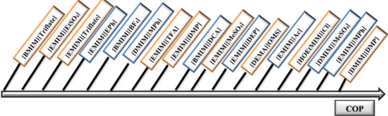
La dernière partie de cette étude est consacrée aux calculs de performances des divers systèmes binaires envisagés dont les propriétés physico-chimiques proviennent de la littérature et/ou de l’expérience. Les simulations numériques réalisées consistent en la résolution des bilans de matière et d’énergie au sein des différents appareils constituant un thermo-transformateur à absorption simple-effet en régime permanent. Elles donnent accès à la connaissance des propriétés du mélange en tout point du cycle et des flux de chaleur échangés. Les niveaux de températures considérées sont de 20°C pour la source basse température, 80°C pour la chaleur résiduaire et 130°C pour la chaleur revalorisée. Les critères de performance retenue sont le coefficient de performance (COP) qui représente le pourcentage de la chaleur résiduaire effectivement revalorisée et le saut thermique maximal qui représente l’élévation maximale de température qu’il est possible d’obtenir. Les résultats de simulation montrent que les performances des fluides de travail constitués de liquide ionique et d’eau sont proches de celles du fluide de travail {H2O + LiBr}. On constate que les liquides ioniques constitués d’une chaîne
alkyle courte conduisent à des COP plus élevés. Ces résultats sont en cohérence avec le fait que la solubilité de l’eau diminue lorsque la chaîne alkyle greffée sur le cation (ou l’anion) augmente (voir figure 2).
6
Figure 2: Influence de la structure du liquide ionique sur le coefficient de performance.
References
[1] J. Ren, Z. Zhao, X. Zhang, Vapor pressures, excess enthalpies, and specific heat capacities of the binary working pairs containing the ionic liquid 1-ethyl-3-methylimidazolium dimethylphosphate, J. of Chem. Thermodynamics, 43 (2011) 576-583.
[2] X. Zhang, D. Hu., Performance analysis of the single-stage absorption heat transformer using a new working pair composed of ionic liquid and water, Applied Thermal Engineering, 37 (2012) 129−135.
[3] L. Dong , D. Zheng, N. Nie, Y. Li, Performance prediction of absorption refrigeration cycle
based on the measurements of vapor pressure and heat capacity of {H2O + [DMIM][DMP]}
system, Applied Energy, 98 (2012) 326−332.
[4] Y.J. Kim, S. Kim, Y.K. Joshi, A.G. Fedorov, P.A. Kohl, Thermodynamic analysis of an absorption refrigeration system with ionic-liquid/refrigerant mixture as a working fluid, Energy, 44 (2012) 1005–1016.
[5] M. Krolikowska, K. Paduszyn, M. Krolikowska, J. Antonowicz, Vapor − Liquid phase equilibria and excess thermal properties of binary mixtures of ethylsulfate-based ionic liquids with water : new experimental data, correlations, and predictions, Ind. Eng. Chem. Res., 53(2014) 18316−25.
7
[6] D. Alonso, T. Cachot, J.M. Hornut, Experimental study of an innovative absorption heat transformer using partially miscible working mixtures, International Journal of Thermal Sciences, 42 (2003) 631–638.
[7] D. Alonso, T. Cachot, J.M. Hornut, Performance simulation of an absorption heat transformer operating with partially miscible mixtures, Applied Energy, 72 (2002) 583–597.
[8] E.D. Bates, R.D. Mayton, I. Ntai, J.H. Davis, Jr., CO2 capture by a task-specific ionic liquid,
J. Am. Chem. Soc., 124 (2002) 926–927.
[9] L.C. Branco, J.N. Rosa, J.J.M. Ramos, C.A.M. Afonso, Preparation and characterization of new room temperature ionic liquids, Chem. Eur. J., 8 (2002) 3671–3677.
[10] H.S. Schrekker, M.P. Stracke, C.M.L. Schrekker, J. Dupont, Ether-functionalized imidazolium hexafluorophosphate ionic liquids for improved water miscibilities, Ind. Eng. Chem. Res., 46 (2007) 7389–7392.
[11] Z.F. Fei, W.H. Ang, T.J. Geldbach, R. Scopelliti, P.J. Dyson, Ionic solid-state dimers and polymers derived from imidazolium dicarboxylic acids, Chem. Eur. J., 12 (2006) 4014–4020. [12] H. Itoh, K. Naka, Y. Chujo, Synthesis of gold nanoparticles modified with ionic liquid based on the imidazolium cation, J. Am. Chem. Soc., 126 (2004) 3026–3027.
[13] Z.F. Fei, D. Zhao, R. Scopelliti, P.J. Dyson, Organometallic complexes derived from alkyne-functionalized imidazolium salts,Organometallics, 23 (2004) 1622–1628.
[14] P. Bonhôte, A.P. Dias, N. Papageorgiou, K. Kalyanasundaram, M. Grätzel, Hydrophobic, highly conductive ambient-temperature molten salts, Inorg. Chem., 35 (1996) 1168–1178. [15] J.G. Huddleston, A.E. Visser, W.M. Reichert, H.D. Willauer, G.A. Broker, R.D. Rogers, Characterization and comparison of hydrophilic and hydrophobic room temperature ionic liquids incorporating the imidazolium cation, Green Chem., 3 (2001) 156–164.
[16] K.R. Seddon, A. Stark, M.J. Torres, Influence of chloride, water, and organic solvents on the physical properties of ionic liquids, Pure Appl. Chem., 72 (2000) 2275–2287.
9
INTRODUCTION
In recent years, industrial and domestic activities increased oil and fossil fuel demand while fossil fuel supplies of the world are limited and the fuel reserves are getting depleted. Moreover, environmental problems represented by the greenhouse effect and increasing CO2 emissions
have been rapidly thrust upon us. Therefore, we are observing a growing interest in energy efficiency, increasing general interest in energy conservation and development of alternative energy sources such as solar energy. At the present time, researchers are interested in developing equipment that facilitate the recovery and efficient use of energy. Reusing thermal waste heat streams from industrial activities, such as power stations, instead of discharging them as thermal pollutant to air and water, receives considerable attention.
Recently, researchers have shown an increased interest in absorption heat pumps, which are considered as a suitable solution for a rational use of waste heat. One of the most promising devices for energy savings, which consume negligible amount of primary energy, is the absorption heat transformer (AHT). In this field of application, absorption heat transformers can use low temperature level heat (waste heat) to produce useful thermal energy at higher temperature level to be recycled in industrial and domestic applications [1, 2, 3, 4].
Absorption cycles were first developed in the nineteenth century and have received much attention in the last few decades. Among current absorption cycle technologies are absorption refrigerators or chillers (AC), absorption heat pumps (AHP) and absorption heat transformers (AHT). This last cycle is attractive because of its high primary energy efficiency compared to other technologies, its ability to use environmentally benign refrigerants and since it allows to decrease the amount of primary energy (i.e. fossil fuels) consumed. Nonetheless, AHT are
rarely used in practice. Their performances remain low (only 30 to 50% of the driving waste heat is effectively upgraded to an interesting temperature level [4]).The commonly used working fluids in AHT are {water + LiBr} and {ammonia + water}. However, these working fluids have technical drawbacks such as corrosion and crystallization, while ammonia is toxic. Those technical limitations lead to long payback periods. However, these problems can be avoided if these working pairs are replaced with new alternatives. Essential efforts to propose new working fluids or multistage structures have still not allowed to widespread this technology [4].
10
Following an idea suggested by several authors [5], mainly for absorption chillers [6, 7, 8], we propose to use alternative working fluids composed of {water + ILs} as working fluids for the absorption heat transformers (AHT). Few experimental works have been realized on this type of absorption cycle. Consequently, the aim of this study is to build a database of new binary systems {water + ILs} in order to evaluate their performance as working fluids in AHT. Ionic liquids are salts in the liquid state having melting point below some arbitrary temperature, such as 100°C (373 K).These solvents consist of an asymmetric, bulky organic cation and a weakly coordinating organic or inorganic anion. A large number of possible combinations enhance the ability to ‘fine tune’ the solvent properties for a specific purpose [9]. The attractive physical and chemical properties of ionic liquids are influenced by the nature of the cation and the nature of cation substituents as well as the polarity and the size of the anion.
ILs have unique properties such as negligible vapor pressure, non-flammability, nontoxicity, good thermal stability, low melting points, wide range of liquid state from room temperature up to 200 or 300 °C, and good solubility for many organic or inorganic chemicals. These features infer to ILs numerous applications, in organic synthesis, separation processes and electrochemistry [10]. For instance, many ILs are completely miscible with water, which nominate them to be investigated as alternatives working fluids in absorption cycle. The use of ionic liquids as absorbents in absorption cycle will enhance absorption of large amount of refrigerant under low temperature conditions and hence, yield to high coefficient of performance [11].
In order to optimize the use of ILs and design the desirable ILs, knowledge of their thermodynamic and physical properties is of great importance. Physical properties such as density and viscosity are related to the mechanical and engineering components associated with a process. For academic research, thermodynamic and chemical properties are also essential to validate the theoretical models.
The main aim of this thesis is to provide a data base of thermodynamic and physical properties for binary systems composed of {water + ILs} by experimentally investigating new ILs and through collecting data from literature for already published ILs properties. Based on the database, the thermodynamic properties of ILs and the variations of properties with the change of cations and anions are studied. Models with good correlation of thermodynamic data for all
11
ILs are developed. Drawing upon these data, simulation of the performance of absorption heat transformers using these binary systems {H2O + ILs} as working fluids is achieved. Simulation
results are compared to the already used working fluids in order to evaluate these binary systems {H2O + ILs} for future use in absorption heat transformers. The present purpose is to examine
the feasibility of using water and ILs in an absorption heat transformer cycle and to show some promising results for this application.
Outline of thesis chapters
Chapter one begins by laying out a full description of ionic liquids, history, their thermodynamic properties and their industrial applications. In addition, the second part is devoted to define the principle of absorption heat transformers. The final part is concerned with presenting a review of thermodynamic properties of binary systems consisting of {water + ILs} used in absorption cycle in particular absorption refrigeration cycle.
Chapter two presents in details the materials, the experimental methods and equipment used for all measurements in this research. Additionally, a brief discussion on thermodynamic theories and models including non-random two liquid (NRTL) model is described. Finally, the third section presents experimental results for the selected binary systems.
Chapter three is devoted to simulate the performance of absorption heat transformers using the new investigated binary systems based on the experimentally and literature thermodynamics properties mentioned in both chapter one and two. In addition, evaluation of the simulation results for all the systems investigated is provided. Finally, the conclusion gives a brief summary and critique of the findings as it discuss recommendations for future work.
References
[1] A. Huicochea, W. Rivera, H. Martínez, J. Siqueiros, E. Cadenas, Analysis of the behavior of an experimental absorption heat transformer for water purification for different mass flux rates in the generator, Applied Thermal Engineering, 52 (2013) 38–45.
12
[2] M. Meza, A. Márquez-Nolasco, A. Huicochea, D. Juárez-Romero, J. Siqueiros, Experimental study of an absorption heat transformer with heat recycling to the generator, Experimental Thermal and Fluid Science, 53 (2014) 171–178.
[3] D. Alonso, T. Cachot, J.M. Hornut, Performance simulation of an absorption heat transformer operating with partially miscible mixtures, Applied Energy, 72 (2002) 583–597. [4] D. Alonso, T. Cachot, J.M. Hornut, Experimental study of an innovative absorption heat transformer using partially miscible working mixtures, International Journal of Thermal Sciences, 42 (2003) 631–638.
[5] X. Zhang, D. Hu., Performance analysis of the single-stage absorption heat transformer using a new working pair composed of ionic liquid and water, Applied Thermal Engineering, 37 (2012) 129−135.
[6] A. Yokozeki, M.B. Shiflett, Water solubility in ionic liquids and application to absorption cycles, Ind. Eng. Chem. Res., 49 (2010) 9496–9503.
[7] L. Dong , D. Zheng, N. Nie, Y. Li, Performance prediction of absorption refrigeration cycle
based on the measurements of vapor pressure and heat capacity of {H2O + [DMIM][DMP]}
system, Applied Energy, 98 (2012) 326−332.
[8] X. Zhang, D. Hu, Performance simulation of the absorption chiller using water and ionic liquid 1-ethyl-3-methylimidazolium dimethylphosphate as the working pair, Applied Thermal Engineering, 31 (2011) 3316–21.
[9] A.L. Revelli, F. Mutelet, J.N. Jaubert, Partition coefficients of organic compounds in new imidazolium based ionic liquids using inverse gas chromatography, Journal of Chromatography A, 1216 (2009) 4775–4786.
[10] L.K. Chellappan, Synthesis of ionic liquids based on new cationic cores. PhD thesis, Department of Chemistry, Faculty of Science, Katholieke Universiteit, Heverlee (Leuven), Belgium; May 2012.
[11] M. Krolikowska, M. Zawadzki, M. Krolikowski, Physicochemical and thermodynamic study on aqueous solutions of dicyanamide – based ionic liquids, The Journal of Chemical
13
CHAPTER ONE
STATE OF THE ART
I.1. Introduction
This first part of this chapter gives a full description of ionic liquids, their thermodynamic properties and industrial applications. After, the second part describes the principle of absorption cycle and absorption heat transformer. The last part is devoted to present a review of thermodynamic properties of working fluids containing {ionic liquids + water}.
I.2. Ionic Liquids
One of the objectives of green chemistry is the design of new chemicals and methods in order to reduce or eliminate the use of hazardous substances. Ionic liquids (ILs) are a new type of environmentally-friendly solvents, which can be defined as the liquids which exclusively consisting of ions (cations and anions), and have low melting point (below 100 °C). Ionic liquids have attracted considerable attention due to their unique properties which distinguish ionic liquids from conventional organic solvents. These are negligible vapor pressure, non-flammability, good thermal stability, low melting points, wide range of liquid state from room temperature up to 200 or 300° C and good solubility for many organic or inorganic chemicals. Therefore, ILs have been proposed as effective substitute for common volatile organic compounds (VOCs) for “green processing” which would inhibit a major source of environmental pollution [1].
In the literature, ionic liquids sometimes are called liquid organic salts, fused or molten salts, ionic melts, NAILs (nonaqueous ionic liquids), room-temperature molten salts, OILs (organic ionic liquids) and ionic fluids [2]. Generally, ionic liquids are composed of a large bulky and asymmetric organic cations and organic or inorganic anions. Asymmetry of the cation is assumed to be the reason of the low melting points of ionic liquids, while the type of the anion is believed to be responsible for many of the physical properties of ionic liquids such as their miscibility with different solvents and hygroscopicity [3].
A major advantage of these solvents is that their physical properties (such as melting point, viscosity, density, and hydrophobicity) can be tuned to design different ionic liquids, to be applied in different applications by selection of different cation, anion, and substituents. Hence,
14
ILs constitute a huge family of chemicals due to the infinite combinations of different cations and anions [4]. Some commonly used ionic liquids (cations and anions) are listed in Table I.1.
Table I.1: Common ILs cations and anions.
Cation Abbreviation Name
Amm Tetra-alkyl ammonium
Ph Tetra-alkyl phosphonium
CnMIM 1-alkyl -3- methyl Imidazolium
15
PIP N-alkyl-N-methylpiperidinium
Anion Abbreviation Name
DMP dimethylphosphate
DCA dicyanamide
MPh methylphosphonate
I.3. History and progress of ionic liquids
In 1914, Paul Walden [5, 6, 7] had synthesized the first low melting point ionic liquid “ethylammonium nitrate ([EtNH3]+[NO3]-)”, with melting point of 12 oC. Nevertheless, their
wide spread use as solvents in chemical and industrial processes for synthesis, separation processes and catalysis has become lately significant. In 1940s, aluminium chloride based molten salts were used for high temperature electroplating. Hurley and coworkers in 1951 [8] synthesized an ionic liquid by warming a mixture of 1-ethylpyridinium chloride with aluminium chloride for low-temperature electroplating of aluminium. During 1970s and 1980s,
16
a thorough investigation on room temperature organic chloride-aluminium chloride was done by Robinson et al. [9] and Hussey et al. [10, 11, 12]. These solvents were used for electrochemical applications in nuclear warheads batteries.
In the early 1970s, Wilkes [13] tried to develop better batteries for nuclear warheads and space probes which required molten salts to operate. These molten salts were hot enough to damage the nearby materials. Therefore, the chemists searched for salts which remain liquid at lower temperatures and eventually they identified one which is liquid at room temperature. Wilkes and his colleagues continued to improve their ILs for use as battery electrolytes and then a small community of researchers began to make ILs and test their properties [14].
During the mid of 1980s, low melting point ionic liquids were used as solvents for organic synthesis. The first major review about ionic liquids was written by Hussey in 1983 [10]. Afterwards, ionic liquids became one of the most promising chemicals as solvents. Generally, ionic liquids such as organo-aluminate, have limited range of applications because they were unstable to air and water. Moreover, these ILs were not inert towards different organic compounds. In 1992, the first reports appeared about the synthesis and applications of water and air stable ILs based on 1-ethyl-3-methylimidazolium cation [EMIM]+ and different anions
such as tetrafluoroborate [BF4]- and hexafluorophosphate [PF6]- [7]. Few years later, Davis et
al. [15] prepared a new class of ionic liquids called "functional ionic liquids" based on cations
derived from the antifungal drug miconazole.
There are literally billions of different structures that may form an IL. The composition and the specific properties of these liquids depend on the type of cation and anion in the IL structure. By combining various kinds of cation and anion structures, it is estimated that 1018 ILs can be
designed [16]. Recently, interest in ionic liquids has been grown significantly in the scientific community (both in academia and industry) with over than 8000 papers have been published in the last decade. This growth can be observed in Figure I.1 (number of publications per year), where the number of publications and patents are increasing rapidly.
17
Figure I.1: Growth rate of ionic liquid publications, 1999-2013 [SciFinder, 2014].
I.4. Classes of ionic liquids
Ionic liquids can be classified into three categories: First, second and third-generation ionic liquids [6]. The first-generation of ionic liquids has been widely studied and is mainly composed of bulky cations like 1, 3-dialkylimidazolium (or N, N'- dialkylimidazolium) or 1-alkylpyridinium (or N-1-alkylpyridinium), and anions based mostly on haloaluminate (III). The interesting property of these ionic liquids is their tunable Lewis acidity. Nevertheless, this generation of ILs is sensitive towards water and it forms hydroxoaluminate (III) species with the aluminium (III) chloride and hence the ionic liquid decomposes. The second-generation ionic liquids are generally air and water stable and can be used on the bench-top. Nevertheless, water-stability does not mean that there is no interaction with water at all. Second-generation ionic liquids are usually hygroscopic and gradually absorb water from the atmosphere. The third generation of ionic liquids has a functional group covalently attached to the cation or to the anion or both. The advantage of introducing a functional group into ionic liquids is the fine-tuning of their properties for a particular application [6, 7].
18
I.5. Physico-chemical properties of Ionic liquids
I.5.1. vapor pressure
Ionic liquids have a negligible vapor pressure even at high temperature due to their ionic nature. Thus, ILs tend not to give off vapors in contrast to traditional organic solvents such as benzene, acetone, and toluene. Kabo et al. [17] evaluated the vapor pressure of [BMIM][PF6] at 298.15
K around 10−11 Pa [16]. Hence, the impact on the environment and the process operation personnel is minimal. Additional, advantage is that volatile products, and even products with conventionally low vapor pressures, can be easily isolated from ionic liquids by distillation.
I.5.2. Activity coefficient for ionic liquids
Activity coefficients give information concerning the interaction between solute and IL. This parameter describes also the degree of non-ideality for a species i in a mixture. The large dataset of activity coefficients at infinite dilution published in the literature may be used to present a general behaviour of solutes with ionic liquids [6, 7].
The values of activity coefficients at infinite dilution for n-alkanes increase with an increase
in carbon number. In most ionic liquids, the high values observed with n-alkanes indicate
their low solubility in ionic liquids. values of n-alkanes are higher than the values obtained
with cyclohexane, alkenes, alkynes and aromatics. Introduction of a double or triple bond in the n-alkanes decreases the values.
Cyclization of the alkane skeleton reduces the value of in comparison to that of the
corresponding linear alkanes. Aromatics with their -delocalized electrons have smaller
values, presumably because of the interaction with the cation species. Using computer simulation, Lynden-Bell et al. [18] showed that the cations are found to interact predominantly with the ring of the benzene while the anions interact with the ring hydrogens to a first approximation.
In the series of chloromethanes, it is usually observed that values strongly increase from
19
indicates that polar compounds have better solubility in the ILs when attractive interaction between polar molecules and the charged ions of the solvent is possible. The values for the
alcohols are relatively small (ranging between 1.2 and 4.6). The lone pair of electrons on the oxygen atom could interact with the ionic liquid cation, and the acidic proton is attracted by oxygen atoms in the cation. values of branched alkanol skeleton are smaller than values
of the corresponding linear alcohol. values of n-alkanols increase with increasing chain
length. values of ethers and amine are higher in comparison with those of the alcohols. For
most solutes, their solubility increase when the alkyl chain length grafted on the ionic liquid increase. The behavior of solutes with ionic liquids is also strongly affected by the nature of the chain grafted on the ionic liquids. For example, grafting a polar chain on the cation of dicyanamide based ionic liquid increases strongly the interactions. Replacing the 1-ethyl-3-methylimidazolium cation by 1-(3-cyanopropyl)-3-1-ethyl-3-methylimidazolium in dicyanamide based ionic liquids, the activity coefficients values of n-hexane are divided by two (241 to 111). The alkoxymethyl-group grafted on the imidazolium cation makes the ionic liquid more polar and with possible anti-microbial activities [19]. Domanska and Marciniak [20] studied the interaction between organic compounds and 1-hexyloxymethyl-3-methyl-imidazolium
bis(trifluoromethylsulfonyl)-imide and 1,3-dihexyloxymethyl-imidazolium
bis(trifluoromethylsulfonyl)-imide. The authors found that ILs with two alkoxymethyl groups in the cation reveals stronger interactions with solutes, e.g. additional interaction of the IL with n-alkanes, alkenes and alkynes (i.e. Van der Waals interaction between alkane chains of the solute and the cation), and also stronger interaction with aromatic hydrocarbons, thiophene and alcohols (hydrogen bonding, n–, or – interactions).
Revelli et al. [21] measured activity coefficients at infinite dilution of organic compounds in the ionic liquid trihexyl(tetradecyl) phosphonium bis(trifluoromethylsulfonyl)imide. As observed with imidazolium-based ionic liquids, cations with a long alkyl chain tend to increase the solubility of most organic compounds in IL. The activity coefficients of 39 organic compounds in this IL are below unity apart from the alkanes and alcohols indicating a strong affinity of the solutes for the ionic liquid. The introduction of a cyanoalkyl chain dramatically decreases the solubility of a polar compounds in ILs. Aromatics, alkenes and alkynes have lower interactions with cyanoalkylimidazolium based ILs than dialkylimidazolium. There is a lack of information concerning piperidinium based ionic liquids. In their recent study, Domanska and Paduszynski, [22] demonstrate that 1-propyl-1-methylpiperidinium
20
bis(trifluoromethyl)sulfonyl)imide behaves like the other measured ionic liquids based on different cations.
I.5.3. Density
Ionic liquids are denser than water with values ranging from 1-1.6 g.cm-3 and their densities
decrease with increase in the length of the alkyl chain in the cation. For instance, imidazolium based ionic liquids coupled with [CF3SO3] ¯ anion, the density has the following behavior
[EMIM]+ > [EEIM]+ > [BMIM]+ > [BEIM]+ with values 1.39 g.cm-3, 1.33 g.cm-3, 1.29 g.cm-3,
1.27 g.cm-3, respectively. This can be explained by the ability of the shorter alkyl chain to
close-packing and therefore achieve a higher density, whereas the bulkiness of the longer chain derivatives leads to less efficient close-packing. The densities of ionic liquids are also affected by the identity of anions. For example, the densities of [BMIM]+ ionic liquid with different
anions, such as BF4¯, PF6¯, TFA¯ and Tf2N¯ are 1.12 g.cm-3, 1.21 g.cm-3, 1.36 g.cm-3 and 1.43
g.cm-3, respectively. Recently, it has been observed that phosphonium-based ionic liquids
possess very low densities: at 30° C, the density of trihexyl tetradecylphosphonium chloride ([P66614][Cl]) is 0.88 g.cm-3, while that of the corresponding [BF4] ¯ was found to be 0.93 g.cm -3 [6, 7].
I.5.4. Viscosity
Knowledge of the viscosity of ionic liquids is of great importance because it plays a key role in stirring, mixing and pumping processes. In addition, viscosity affects other transport properties such as diffusion and thermal conductivity as it affects heat and mass transfer. In general, ionic liquids are more viscous than common molecular solvents and their viscosities are ranging from 10 mPa.s to about 500 mPa.s at room temperature. The viscosity of ionic liquids mainly depends on van der Waals forces and hydrogen bondings. Both anions and cations have a strong influence on the viscosity of ILs. Toduka et al. [23] and Chellappan [7] found that the alkyl chain length and the nature of the anion have an important influence on the viscosity of ionic liquids. The fluorinated anions such as [BF4]¯and [PF6]¯ form viscous ionic liquids because of
the formation of complexes with hydrogen bonding donors. It was also found that the viscosity of ionic liquids depends on the alkyl chain length of the cations. It is obvious that alkyl groups
![Figure I.14: Viscosity for the binary mixtures {water (1) + [EMIM][DMP] (2)} at different temperatures and mole fractions of IL x 2 = 0.2; x 2 = 0.4; x 2 = 0.6;](https://thumb-eu.123doks.com/thumbv2/123doknet/14495286.718197/80.892.189.706.100.533/figure-viscosity-binary-mixtures-water-different-temperatures-fractions.webp)
![Figure II.10: Experimental VLE data for the investigated binary systems {H 2 O (1) + [DMIM][MeSO 4 ] (2)}: (a) Isobaric VLE data symbols are experimental data at different mole fractions of [DMIM][MeSO 4 ]: ( ) x 2](https://thumb-eu.123doks.com/thumbv2/123doknet/14495286.718197/109.892.187.708.105.797/figure-experimental-investigated-systems-isobaric-experimental-different-fractions.webp)
![Figure II.12: Experimental VLE data for the investigated binary systems {H 2 O (1) + IL (2)} symbols are experimental data at different mole fractions of ILs and — , calculated by NRTL equation: (a) [BMIM][DCA]: ( ) x 2 =0.1; ( ) x 2 =0.2; ( ) x 2 =0.3](https://thumb-eu.123doks.com/thumbv2/123doknet/14495286.718197/111.892.187.704.108.785/figure-experimental-investigated-experimental-different-fractions-calculated-equation.webp)