HAL Id: tel-01525039
https://tel.archives-ouvertes.fr/tel-01525039
Submitted on 19 May 2017HAL is a multi-disciplinary open access archive for the deposit and dissemination of sci-entific research documents, whether they are pub-lished or not. The documents may come from teaching and research institutions in France or abroad, or from public or private research centers.
L’archive ouverte pluridisciplinaire HAL, est destinée au dépôt et à la diffusion de documents scientifiques de niveau recherche, publiés ou non, émanant des établissements d’enseignement et de recherche français ou étrangers, des laboratoires publics ou privés.
Design and prototyping of robust architectures for UHF
RFID Tags
Omar Abdelmalek
To cite this version:
Omar Abdelmalek. Design and prototyping of robust architectures for UHF RFID Tags. Mi-cro and nanotechnologies/MiMi-croelectronics. Université Grenoble Alpes, 2016. English. �NNT : 2016GREAT088�. �tel-01525039�
DOCTEUR DE LA COMMUNAUTE UNIVERSITE
GRENOBLE ALPES
Spécialité : Nanoélectronique et Nanotechnologies.
Arrêté ministériel : 7 août 2006
Présentée par
Omar ABDELMALEK
Thèse dirigée par Vincent Beroulle et codirigée par David HELY
préparée au sein du Laboratoire de Conception et d’Intégration des Systèmes (LCIS)
dans l'École Doctorale EEATS
Conception et prototypage
d'architectures robustes de
tags RFID UHF
Thèse soutenue publiquement le 20 octobre 2016, devant le jury composé de :
M, Bruno ROUZEYRE
Professeur des Universités, Université Montpellier II, Rapporteur
M, Romain, OLIVIER
Professeur des Universités, Université de Cergy-Pontoise, Rapporteur
M, Nacer, ABOUCHI
Professeur des Universités, CPE LYON, Président
M, Vincent, Beroulle
Maître de Conférences,Grenoble INP, Directeur
M, David, HELY
-1-
English Title:
DESIGN AND EMULATION OF ROBUST
ARCHITECTURES FOR UHF RFID TAGS
-2-
ACKNOWLEDGMENTS
Firstly, I would like to express my sincere gratitude to my advisors Prof. Vincent
Beroulle and David Hély for the continuous support of my Ph.D study and related
research, for his patience, motivation, and immense knowledge. His guidance
helped me in all the time of research and writing of this thesis. I could not have
imagined having a better advisor and mentor for my Ph.D study.
Besides my advisor, I would like to thank the rest of my thesis committee: Prof.
Bruno ROUZEYRE, Prof. Romain OLIVIER, and Prof. Nacer ABOUCHI
,for
their insightful comments and encouragement, but also for the hard question
which incented me to widen my research from various perspectives.
I thank Christophe Medina (with whom I shared the joys and galleys of the
prototype test at RFT LAB platform).
Last but not the least, I would like to thank my family: my wife my daughter
INAYA, to my parents and to my brothers and sister for supporting me spiritually
throughout writing this thesis and my life in general.
Finally, I would like to thank my great mother whom I lost during my thesis, and
these prayers for me.
-3-
Résumé:
Les systèmes RFID sont de plus en plus utilisés dans des applications critiques fonctionnant dans des environnements perturbés (ferroviaire, aéronautique, chaînes de production ou agroalimentaire) ou dans des applications où la sécurité est essentielle (identification, lutte contre la contrefaçon). Pourtant, ces systèmes faibles coûts sont peu robustes par nature. Pour les applications critiques, les défaillances des tags RFID peuvent avoir des conséquences catastrophiques ou créer des failles de sécurité importantes. Ces défaillances peuvent avoir des origines nombreuses : par exemple, des origines matérielles dues au vieillissement naturel des circuits intégrés ou à des attaques.
L'objectif de la thèse est d'accroitre la robustesse des tags UHF passifs en proposant et validant de nouvelles architectures numériques de puces RFID robustes à la fois aux défaillances et aux attaques matérielles. Les approches de durcissement des circuits intégrés étudient généralement leur robustesse par simulation et ce de manière indépendante à la validation de leur conception. La méthode la plus courante afin de valider la robustesse d'un circuit repose sur l'injection de fautes par simulation. Pour les tags RFID, ce type d'approche par simulation est problématique car les performances des puces dépendent de nombreux paramètres difficilement modélisables globalement. En effet, le fonctionnement d'un tag dépend de son environnement électromagnétique, du nombre de tags présents dans le système, des protocoles mis en œuvre, l’objectif de cette thèse est développer une méthodologie basée sur le prototypage permettant d'éviter des simulations complexes.
Une plateforme RFIM d’émulation de tag RFID à base FPGA qui conforme à la norme EPC C1 Gen2 a été développée, l’émulateur du tag RFID a été validé fonctionnellement dans un environnement réel. La plateforme RFIM utilise la technique d'instrumentation permettant l'injection de fautes dans les circuits numériques sur FPGA. Grâce à des campagnes d'injection de faute émulées La plateforme RFIM permet d’analyser l'effet sur l'ensemble du système des fautes injectées dans le tag, et valider de nouvelles architectures numériques de tags RFID robustes. La plateforme RFIM a été a été notamment utilisée pour démontrer les effets de nouvelles attaques contre les systèmes RFID reposant sur l'insertion de tags fautifs ou malveillants qui contient un cheval de Troie matériel dans les systèmes. Finalement, cette plateforme d’émulation mène au développement d'une contre-mesure contre les effets des fautes. Cette contre-mesure a été mise en œuvre et évaluée dans un environnement réel avec un lecteur RFID et plusieurs RFID tags.
Mots-clés :
-4-
RFID tags are more and more used for critical applications within harsh environments (aeronautics, railways) or for secure applications such as identification, countermeasure against counterfeiting. However, such low cost systems, initially designed for non-critical applications with a high volume, are not robust by themselves. For critical applications, a malfunction of RFID chip may have serious consequences or induce a severe security breach for hackers. Dysfunctions can have many origins: for instance, hardware issues can be due to aging effects or can also be due to hackers attack such as optical or electromagnetic fault injection. It is thus a common practice for critical applications to increase the robustness of RFID system. The main purpose of this PhD Thesis is to increase UHF tags robustness by proposing new digital architectures of RFID chips which would be resilient against both hardware attacks and natural defects.
Usual design techniques for robustness IC improvement consist in evaluating the design robustness by simulation and to do this independently of the design validation. The main technique for robustness evaluation is the simulation based faults injection. Within the RFID context such an approach only based on simulation has several drawbacks. In fact, simulations often are inaccurate because the system behavior relies on several parameters such as the global electromagnetic environment, the number of tags present in the reader field, the RFID protocol parameters.
The purposes of this PhD are to develop a design method dedicated to RFID system based on hardware prototyping in order to avoid time consuming simulations and then to evaluate the design within a real environment.
The hardware prototyping based on FPGA allows the design to be validated in a real environment. Moreover, using instrumentation techniques for fault injection within FPGA, it will be then possible to analyze the effects of faulty tags on the global system in terms of safety and security and then to propose countermeasures.
In this thesis an FPGA based emulation platform called RFIM has been developed. This platform is compliant to EPC C1 Gen2 RFID standard. The RFID tag emulator has been validated functionally in a real environment. The RFIM platform uses the instrumentation technique for injecting faults in the digital tag circuit. Through fault injection campaigns RFIM platform can analyze the effect on the entire system of the faults injected into the tag, and ten validate new robust digital architectures. The RFIM platform has been used to demonstrate the effects of further attacks against RFID systems based on the insertion of faulty or malicious tag that contains a hardware Trojan. Finally, RFIM platform helps to develop countermeasures against the fault effects. These countermeasures have been implemented and tested in a real RFID environment with several tags and reader.
Keywords
-5-
Contents
1
Introduction ... 13
2
Safety and RFID Systems ... 16
2.1 Introduction ... 17
2.2 RFID technology ... 17
2.2.1 RFID technologies ... 18
2.2.1.1 Frequencies used in RFID Technologies ... 18
2.2.1.2 RFID tag types ... 19
2.3 RFID system components ... 21
2.3.1 Passive UHF RFID tag architecture ... 21
2.3.2 UHF RFID reader architecture ... 22
2.3.3 RFID applications ... 23
2.4 EPC global (Electronic Product Code) ... 25
2.4.1 EPC C1 Gen2 features ... 26
2.4.1.1 Physical Layer Communication Features ... 26
2.4.1.2 Data encoding ... 27
2.4.1.3 Miller and FM0 encodings: tag to Reader link ... 28
2.4.1.4 Sessions & inventoried flags ... 30
2.4.1.5 Tag memory ... 31
2.4.1.6 Commands and state machine ... 31
2.5 Safety and security validation of UHF RFID systems ... 36
2.5.1 Safety issues ... 37
2.5.2 Interaction faults that include all external faults RFID Heterogeneity and complexity: ... 39
2.6 Conclusion: ... 41
3
RFID validation platforms and robustness evaluation platforms .. 43
3.1 Introduction ... 44
3.2 RFID Simulation platforms ... 44
3.3 RFID Emulation platforms ... 46
3.4 Fault injection ... 49
3.4.1 Farm Model ... 49
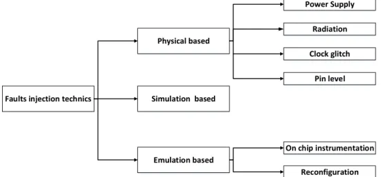
3.4.2 Fault Injection Techniques ... 50
3.4.2.1 Physical-based fault injection ... 51
-6-
3.4.2.3 Emulation-based fault injection ... 53
3.5 Conclusion ... 58
4
RFID emulator and robustness evaluation platform ... 60
4.1 Introduction ... 61
4.2 Proposed Emulator Architecture ... 61
4.2.1 Description of the emulator ... 61
4.2.1.1 UHF RFID tag Analog front-end ... 62
4.2.1.2 UHF RFID tag digital baseband architecture (RT level schematics) ... 63
4.3 RFID tag validation ... 73
4.3.1 RFID Emulator Functionality Validation ... 73
4.3.2 RFID Emulator Validation in UHF RFID Test Platform ... 76
4.4 Architecture and system descriptions of the fault emulator for RFID System (RFIM) ... 78
4.4.1 Set F ... 79
4.4.2 Set A ... 79
4.4.3 Set R ... 79
4.4.4 Set M ... 79
4.4.5 FARM set of RFIM platform ... 80
4.4.6 Fault injector ... 82
4.4.7 Fault injection mechanism: ... 85
4.5 Experiment using RFIM platform ... 87
4.5.1 Fault Effect Evaluation on read rate ... 89
4.5.2 Standalone tag Evaluation ... 89
4.5.3 Fault injection effects on tag behavior ... 92
4.5.4 Experiments and analysis of the fault injection data ... 93
4.5.4.1 Fault locations ... 93
4.5.4.2 Fault Models ... 94
4.5.4.3 Fault Timing ... 94
4.5.4.4 Fault value ... 94
4.5.5 Fault injection campaigns ... 95
4.5.5.1 Workload 1 ... 96
4.5.5.2 Workload 2 ... 97
4.5.5.3 Workload 3 ... 98
4.5.5.4 TRcal ... 100
-7-
4.5.5.6 Reader to tag calibration RTcal ... 100
4.5.5.7 Command register ... 101
4.5.5.8 Target and M parameters ... 101
4.5.5.9 The slot counter and Q parameter ... 102
4.5.5.10 The session parameter ... 102
4.5.5.11 Fault propagation path ... 103
4.6 EPC C1 Gen2 tag enhancement reliability ... 103
4.6.1 Countermeasure against SEU error to enhance the tag read rate ... 103
4.6.2 Countermeasures against the SEU faults ... 105
4.6.2.1 Sequence states integrity testing ... 105
4.6.2.2 Spatial redundancy ... 105
4.6.3 Assertion Based On-line Fault Detection ... 106
4.6.4 Error code correction for Fault Detection ... 111
4.7 Conclusion ... 115
5
Threat evaluation of Hardware Trojan within RFID System ... 116
5.1 Introduction ... 117
5.2 Hardware Trojans ... 118
5.2.1 Hardware Trojan Components ... 118
5.2.2 Hardware Trojan Insertion phase and location... 118
5.2.3 Trojan Taxonomy ... 120
5.2.4 Hardware Trojan trigger Taxonomy: ... 122
5.2.4.1 Analog trigger: ... 122
5.2.4.2 Digital trigger: combinational and sequential ... 122
Rare sequence Hardware Trojan trigger ... 123
5.2.5 Hardware Trojan payload Taxonomy... 124
5.2.5.1 Functional Modification ... 124
5.2.5.2 Specification modification ... 124
5.2.5.3 Information Leakage ... 125
5.2.5.4 Denial of Service ... 125
5.2.6 Hardware Trojan detection approaches ... 125
5.2.6.1 Destructive detection approaches... 126
5.2.6.2 Non-Destructive detection approaches ... 126
5.3 Hardware Trojan in RFID System ... 129
5.3.1 Objective of Hardware Trojan in RFID ... 130
-8-
5.3.3 Denial of Service Attack ... 130
5.3.4 Data eavesdropping/modification ... 130
5.3.5 RFID System specificities ... 131
5.3.6 Trigger design and validation ... 133
5.3.6.1 Triggering issues ... 133
5.3.6.2 Triggers sensitive to parametric changes (HT1) ... 134
5.3.6.3 Triggers sensitive to a sequence of commands (HT2) ... 135
5.3.6.4 Modification of frame contents (HT3) ... 137
5.3.7 Fault Injection based Validation of Hardware Trojans ... 138
5.3.8 Triggers Evaluations ... 139
5.3.9 Payload design and validation: ... 139
5.3.9.1 Denial of services HP1 ... 139
5.3.9.2 Leak sensitive information HP2 ... 140
5.3.9.3 Modify functionality HP3 ... 141
5.3.9.4 Modify specification HP4 ... 141
5.4 On line monitoring for Hardware Trojan Detection:... 142
5.5 Conclusions ... 143
6
Conclusion and perspective ... 145
6.1 Conclusions ... 146
6.2 Perspectives ... 148
Reference ... 150
-9-
List of Figures:
Figure 2.1: RFID system operations 17
Figure 2.2: RFID Frequencies 18
Figure 2.3: Semi passive RFID tag example 20
Figure 2.4: Example of passive UHF RFID tag 20
Figure 2.5: Block diagram of a UHF RFID tag 21
Figure 2.6: Detailed Block diagram of a UHF RFID tag 21
Figure 2.7: Block diagram of UHF RFID tag architecture 22
Figure 2.8: Block diagram of UHF RFID reader 23
Figure 2.9: Application areas of RFID technology 25
Figure 2.10: Pulse-Interval Encoding (PIE) Baseband Symbols 27
Figure 2.11: Data encoding in PIE format. 27
Figure 2.12: Reader-to-tag frame sync. 28
Figure 2.13: Reader-to-tag preamble. 28
Figure 2.14: FM0 encoding the tag to reader link. On the left), representation of bits 0 and 1.
On the right a few possible sequences [EPC2008] 29
Figure 2.15: Miller encoding schemes 29
Figure 2.16: tag to reader Miller encoding 30
Figure 2.17: Memory banks of a tag [EPC2008]. 31
Figure 2.18: Commands and state machine 32
Figure 2.19: Simplified protocol followed between a reader and a tag [EPC2008] 33
Figure 2.20 : Tag state diagram [EPC2008] 34
Figure 2.21: Access protocol of an EPC C1 Gen2 tag 36
Figure 2.22: Error propagation in digital system 38
Figure 2.23: Relationship among faults, errors, and failures 39
Figure 2.24: RFID System with several tags 40
Figure 2.25: Layers for UHF RFID system modeling 40
Figure 2.26: Hardware layer structure for UHF RFID system modeling 41
Figure 3.1: FARM model [Arlat1992]. 49
Figure 3.2: Modified FARM model [Elks 2005] 50
Figure 3.3: Taxonomy of fault injection techniques 51
Figure 3.4: Instrumentation based register mask [Civera 2001B] 56
Figure 3.5 RFID tag emulation environment 58
Figure 4.1: EPC C1 Gen2 tag block diagram 62
Figure 4.2: Analog Front-End architecture 62
Figure 4.3: RFID Baseband architecture 64
Figure 4.4: PIE decoder RTL schematic 64
Figure 4.5: Query command parameters 65
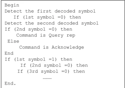
Figure 4.6: Part of the pseudo-code of the command decoder 65
Figure 4.7: CRC5 circuit 66
Figure 4.8: Pseudo code for tag to reader link frame encoding 67
Figure 4.9: RTL schematic of FM0 and Miller encoder 67
Figure 4.10 : Pseudo code for slot counter implementation 69
Figure 4.11: Slot counter 69
Figure 4.12: Session flag controller 70
-10-
Figure 4.14: Pseudo code for backscatter clock generator design. 72
Figure 4.15: Backscattering clock generator 72
Figure 4.16: RFID tag design and verification flow 74
Figure 4.17: Finite state machine functional simulation with a unit testbench 75
Figure 4.18: RFID tag Global test bench 75
Figure 4.19: Tag validation using the protocol analyzer 77 Figure 4.20: Experimental results of UHF RFID baseband response 77 Figure 4.21: RFIM platform for faults injection and monitoring 80
Figure 4.22: Log file for communication analysis 81
Figure 4.23: Bloc diagram of the fault injector 82
Figure 4.24: Permanent fault injection 83
Figure 4.25: Flowchart of the transient faults injection 84
Figure 4.26: Fault injection rate depending Ctrl 85
Figure 4.27: Fault injection in tag registers and propagation 85 Figure 4.28: Faulty transition in the FSM due to fault injection 86
Figure 4.29: Register Fault injection 86
Figure 4.30: Transient Fault Injection Simulation 87
Figure 4.31: Successful tag Identifications 89
Figure 4.32: Fault effects on each inventoried tags 91
Figure 4.33: Result for second third party reader 92
Figure 4.34: Main components of the fault injection environment 2 93
Figure 4.35: Improved RFIM Architecture 95
Figure 4.36: Relative percentages of each of the response 96
Figure 4.37: Fault tree in tag baseband 97
Figure 4.38: Fault path propagation 98
Figure 4.39: Fault duration effect on RFID tag Baseband 99
Figure 4.40: TRcal Registrer SEU faut effets 100
Figure 4.41: Impact of RTcal on the tag to reader communication timing 101 Figure 4.42: M and target register fault injection effect 102 Figure 4.43: Fault propagation in the case of TRcal register 103
Figure 4.44: TMR Protection 103
Figure 4.45: Fault Effect with Redundancy 104
Figure 4.46: Design of hardware redundancy using prediction 106 Figure 4.47: Proposed on-line fault detection approach based on hardware assertions and
applied on a developed RFID tag architecture. 108
Figure 4.48: Reading detected faults numbers with RFID reader software. 109 Figure 4.49: Limitation of simple parity check [Pfanz2002] 111 Figure 4.50: Row-and column-Parity checks [Pfanz2002] 112 Figure 4.51: Limitation of Row and column-parity check [Pfanz2002] 112 Figure 4.52: Cross-parity organisation for register files [Pfanz2002] 113 Figure 4.53: Cross parity coupled with the prediction parity architecture [Pfanz2002] 114 Figure 5.1: General structure of a Hardware Trojan in a design 118
Figure 5.2: IC life cycle [HeLi2016] 119
Figure 5.3: Hardware Trojan attacks by different parties at different stages of IC life cycle
[Bhnia2014]. 120
Figure 5.4: Global view of Hardware Trojan Taxonomy 121
-11-
Figure 5.6: Combinational triggered HT [Chen2008] 122
Figure 5.7: Synchronous counter Trojan [Bhunia2010] 123
Figure 5.8 : Hardware Trojan Detection Techniques [Mark2011] 126 Figure 5.9: Assistive approach to detect Hardware Trojan [Chakraborty2008] 127
Figure 5.10 : RFID IC tag Lifecycle 129
Figure 5.11: Malicious tags in an infected RFID System 129 Figure 5.12: RFID Emulation based platform for online monitoring of tag 132
Figure 5.13: Hardware Trojan in System Emulation 132
Figure 5.14: Example of tag Reader communication 134
Figure 5.15 : a) Reader to tag preamble frame, 135
Figure 5.16: Hardware Trojan HT2a trigged by BlockErase command 135 Figure 5.17: a) FSM modification b) Hardware Trojan trigger HT2b design 136
Figure 5.18: EPC C1 Gen2 Frame [EPC2008] 137
Figure 5.19: HT3b design, CRC calculation with a malicious data 138 Figure 5.20: Payload HP1 Modify Specification (parameters) 140
Figure 5.21: Payload HP2, leak of information 141
Figure 5.22: Payload HP3 Disable the mechanism of password verification 141
-12-
List of Tables:
Table 3.1: Experimental platform comparison 46
Table 3.2: Survey of RFID emulator 48
Table 4.1: EPC C1 Gen2 command 66
Table 4.2: Pseudo random number generator 68
Table 4.3: Fault injection rates given by ideal random generators 84 Table 4.4: Pseudo-random faults injections rates obtained by simulation with 10000 cycles 85
Table 4.5: Observed response modes 96
Table 4.6: Result of fault injection to determine the faults propagation 98 Table 4.7: Number of reading over the 100 inventory rounds for each parameter and
depending on the transient fault duration Register fault injection effect 99 Table 4:8: Device utilization table for the tag with TMR and tag without TMR 104
Table 4:9: ECC types using with prediction circuit 105
Table 4:10: Type of used assertion 109
Table 4:11: Fault detection effectiveness 110
Table 4:12: RFID tag area occupation on Spartan-3E FPGA before and after implementation
of on-line fault detection infrastructure circuit 110
Table 4:13: RFID tag area occupation before and after implementation of cross parity checks 115
Table 5.1: Hardware Trojan Trigger 123
Table 5.2: Triggers Evaluation 139
Table 5.3: HP1 payload effects of RFID tag 140
-13-
Chapter 1
-14-
UHF RFID tags are increasingly used for critical applications within harsh environments (aeronautics, railways) or for secure applications such as identification, countermeasure against counterfeiting. However, such low cost systems, initially designed for non-critical applications with a high production volume, are not robust by themselves. For critical applications, a malfunction of the RFID chip may have serious consequences or may induce a severe security breach for hackers. Dysfunctions can have many origins: for instance, hardware issues can be due to aging effects or can also be due to hacker attacks such as optical or electromagnetic fault attacks. It is thus a common practice for critical applications to increase the robustness of RFID systems. The main purpose of this PhD thesis is to increase UHF tag robustness by first proposing a dedicated robustness evaluation platform and then proposing new digital architectures of UHF RFID chips which would be resilient against both hardware attacks and natural defects.
Classical design techniques for robustness IC improvement aim to evaluate the design robustness by simulation with fault injection. Within the RFID context such an approach only based on simulation has several drawbacks. In fact, simulations are often inaccurate because the RFID system are heterogeneous and their behavior relies on several parameters such as the global electromagnetic environment, the number of tags present in the reader field, the RFID protocol parameters, etc.
The purposes of this thesis are to develop validation methods and tools dedicated to RFID system in order to avoid time consuming simulations and then to evaluate the design within a real environment.
In this thesis, an FPGA based emulation platform called RFIM is presented. This platform is compliant to EPC C1 Gen2 RFID standard [EPC2008]. The RFID tag emulator has been validated functionally in a real environment. The RFIM platform uses the instrumentation fault injection technique to inject faults in the digital tag circuit. Thanks to fault injection campaigns, RFIM platform allows analyzing the effects of the faults injected into the tag, and then helps designer validating new robust digital architectures within a real RFID environment. The RFIM platform can be used to demonstrate the effects of malicious attacks against RFID systems based on fault injection or malicious tag modification via Hardware Trojan.
Chapter 1 Introduction
-15-
Chapter 2 of this thesis is devoted to a presentation of the general concepts of RFID technologies: classification, regulations and RFID standards. We show the importance and the benefits of using RFID technology, especially in critical applications, which demand a high level of security and dependability. Following this presentation, we discuss about the heterogeneity and complexity of RFID systems. These complexity and heterogeneity involve that their dependability improvement is a difficult task. In this chapter, we finally justify the need for a validation platform that takes into account all the RFID system parameters.
In chapter 3, we present a state of the art of different RFID system validation platforms and a brief description of existing robustness evaluation tools. In the first part of this chapter, we detail the RFID system simulation based platforms and then we give more detailed descriptions on RFID system emulation platforms. In the second part of this chapter, we discuss the methodology of the fault injection. Then, we conclude this chapter with a state of art of different fault injection platforms that are proposed in literature. We distinguish between two categories of fault injection platforms: one based only on simulation and other based on emulation or prototyping.
In chapter 4, we present our RFID tag emulator (RFIM) with fault injection capabilities to emulate errors in order to validate the robustness of both tag architectures and its protocol. Using RFIM, in system fault injection is carried out and the results are presented and detailed. Finally, some architecture enhancements in order to increase the tag robustness are presented and evaluated.
In chapter 5, we focus on the RFID vulnerability to Hardware Trojan by presenting general research results on HT insertion and detection. Then, we show how the hardware emulation platform RFIM can help to evaluate some trigger and payload of Hardware Trojan. Finally, we discuss some countermeasures which could be designed at the system level in order to protect RFID system against untrusted RFID tags.
Finally the conclusion summarizes the main results of this work, and discusses perspectives.
-16-
Chapter 2
Chapter 2 Safety and RFID Systems
- 17 -
2.1 Introduction
In this chapter, we will present RFID systems from technology issues to usage and standard issues. We will first provide important information on RFID technology which are necessary to set-up the context of this work. Then, we will show the importance and the benefits of using RFID technology, especially in critical applications, which demand a high level of security and dependability. RFID systems are complex and heterogeneous systems. As a result to this complexity and this heterogeneity, analyzing and improving the dependability characteristics of such a system is a complex task. In this chapter, we will justify the need for a validation platform which deals with all the RFID system elements.
2.2 RFID technology
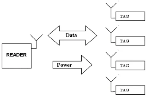
RFID (Radio Frequency Identification) is an automatic identification technology that uses radio frequency waves to identify objects attached to a tag when they pass close to an RFID reader. When communication is established between a tag and a reader, the data contained in the tag are transferred to the reader. The data in the tag can also be modified with specific commands issued by the reader. The radiated electromagnetic waves transmitted by the reader include information and at the same time provide energy to the tag which allows this one to process data before to backscatter information to the reader.
Figure 2.1: RFID system operations
Figure 2.1 describes the general operations of an RFID system. We can summarize the communication between a tag and a reader as follows:
The server must be able to handle the reader and to generate appropriate commands.
- 18 -
Communication between the reader and the tag is done by radio frequency signals.
The signal carrying command information is generated by the reader.
The carrier signal is emitted from the reader antenna to the tag.
The tag receives the transmitted signal, extracts digital information and then transmits the response to the reader
The reader antenna receives the modulated signal from the tag, and then demodulates it.
The reader decodes the received signal and extracts digital information.
The host server retrieves the received information; this information can be filtered, modified or aggregated before being stored in the database of the host.
2.2.1 RFID technologies
2.2.1.1 Frequencies used in RFID Technologies
Since RFID technologies use radio waves for communication between tag and reader, these technologies are then classified by frequency bands in which they operate. The different frequencies are allocated by regulatory authorities who set very specific rules to use each frequency. RFID systems work from Low frequency (LF) to Super High frequency (SHF). These frequencies have been standardized to avoid interferences from other devices of other technologies. All frequencies used for RFID technology are summarized in Figure 2.2.
Chapter 2 Safety and RFID Systems
- 19 -
a) Low frequency
From 100 kHz to 500 kHz, the reading distance is a few centimeters; these frequencies are used in industrial environments as well as for animal tracking. This band allows reading in any environments but only for short distances (less than 10 centimeters).
b) Medium frequency
From 10 MHz to 15 MHz with a reading distance of 50 to 80 cm, these frequencies are particularly used in library logistics, flows monitoring and access control. This band allows a medium reading distance (about one meter). Tags using this frequency range are more sensitive to nearby presence of metal or liquid.
c) High frequency
From UHF band (850-950 MHz) to SHF band (2.4 to 5.8 GHz), the reading distance is several meters (in free air, this distance can be reduced by the presence of metal or liquid). These frequencies are particularly used in supply chain management.
2.2.1.2 RFID tag types
RFID tag can also be classified according to their power supply source. We distinguish three different power supply types:
a) Active tag
This type contains an embedded battery allowing them to emit a signal without needing to be remotely powered. This type of tag can achieve reading distances of a few meters. They are mainly used to send big amounts of information over long distances. They have the disadvantage of being more expensive than other systems; they require maintenance service and are less integrated.
b) Semi-passive tag
Semi-passive tags, also called semi-active, are very similar to the active tags since they are also powered by an embedded energy source (Figure 2.3). The difference between these two types of tag is related to the battery used. The power of the semi-active RFID chip is not used to send any signal but for storing data between successive communication exchanges. The semi-active tags use backscattering techniques to send back the reader signal.
- 20 -
These tags are often used to record data during goods transporting. They are particularly useful in the field of food traceability and logistic traceability that require to:
Register temperature changes during transport,
Surveillance of equipment fleets, etc.
Figure 2.3: Semi passive RFID tag example c) Passive tag
Passive RFID tags are the most deployed because of their low cost, miniature size, and the simplicity of their architecture. They do not include neither battery nor RF transceiver as the semi-passive and the active tags do. This type of tag use the backscattering technique to response to reader commands. The backscattering technique consists in modulating the scattered electromagnetic wave incident from the reader. The scattered wave is modulated by changing the electrical impedance of the tag antenna. A passive backscatter tag receives the power needed to operate from the wave incident from the reader. This type of tag is compact and simple. The passive tag is composed of an antenna for communicating with the reader and an electronic chip which integrates memories that can store data to be transmitted. All these elements are combined in a packaging as shown in Figure 2.4
Chapter 2 Safety and RFID Systems
- 21 -
2.3 RFID system components
In this work we focus on passive tags. Indeed, thanks to its low cost, passive UHF RFID technology remains the most deployed one for traceability applications.
2.3.1 Passive UHF RFID tag architecture
A passive UHF RFID tag consists of an antenna and an integrated circuit that includes both the radio frequency part (Analog front end), and the digital part (digital baseband). An overview diagram of an UHF tag is shown in Figure 2.5.
Tag
Digital PART RF Front End AntennaChip
Figure 2.5: Block diagram of a UHF RFID tag
ENERGY Haversting Antenna Signal receiver Load Modulation
Figure 2.6: Detailed Block diagram of a UHF RFID tag
The different features of the radio frequency front-end, as shown in Figure 2.6, can be described as follows:
The energy recovery function is performed by a rectifier which can recover a DC voltage from the RF carrier sensed by the antenna. This voltage is supposed to power the tag.
Frequently, the rectifier is connected to a regulator or a voltage limiter allowing the voltage stability and protecting the chip from overvoltage risks.
- 22 -
All requests transmitted by the reader are provided to the signal receiver block. This block contains a demodulator, a baseband filter and an analog to digital converter. The demodulation type used in UHF RFID tags is the ASK (Amplitude Shift Keying).
Finally, the backscattering function is performed by the load modulation block which modifies the load at the input of the antenna.
We present in Figure 2.7 a block diagram illustrating in more details the complete UHF RFID tag architecture. The radio frequency part (RF Front-End), contains ASK demodulator, a rectifier, and load modulation part.
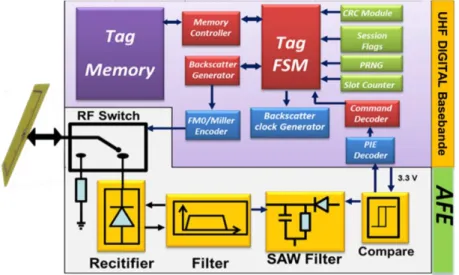
The digital baseband contains the power management block to ensure a stable energy supply to the tag and the baseband signal processing block used to encode and to decode the digital baseband signal. The role of the modulation control block is to control the load modulation part to generate the backscattering signal. Finally, the digital part manages the execution of the RFID protocol [EPC2008].
Digital part - Memory -Decoding -Response management baseband signal processing Power Management Modulation control Demodulator rectifier Load Modulation Digital Part Baseband
Analog Front End
Antenna
Figure 2.7: Block diagram of UHF RFID tag architecture
2.3.2 UHF RFID reader architecture
The RFID reader is the interface between the application/server and the RFID tags as shown in Figure 2.1. Executed by the server, the middleware is a software which is used to filter the tags data and manage several readers across a network. The reader just ensures the transfer of all information extracted from the tags to send it to the middleware.
Chapter 2 Safety and RFID Systems
- 23 -
The main role of the reader is the communication establishment: it aims at managing the communication with the RFID tags and with the server. It executes the middleware to communicate with the server and controls the communication protocols to communicate with tags. For example, for UHF RFID, one standard protocol is the EPC C1 Gen2 [EPC2008]. This protocol will be described in the section 2.4.1. All these functions are performed by a digital part (as shown in Figure 2.8), composed of microprocessor, memory and an RF interface controller.
Digital part:
- Protocol management - Coding and encoding - Application
Transceiver
Signal modulation
Carrier signal
Receiver
Digital part
Analog Front End
Antenna
Figure 2.8: Block diagram of UHF RFID reader
All RFID reader features are summarized in the block diagram of Figure 2.8. The digital part ensures the digital signal generation. This signal contains information to be transmitted to the tag. The digital part also manages information returned by the tag. In addition to the implementation of the communication protocol, the digital part is able to encode and to decode signals and optionally to encrypt and to decrypt information, or to perform any other functions required by the application (middleware).
As shown in Figure 2.8 the physical layer of the communication is realized by a Radio Frequency Front-End which consists of a transmitter and a receiver. This RF front-end is thus responsible for generating carrier frequency to remotely supply the tag.
2.3.3 RFID applications
Applications based on RFID systems are more and more numerous. We will not describe in this document all the possible applications. Since we are interested by critical systems, we will only focus on critical applications that use RFID technology: security, health and military applications.
- 24 - a) Health
In the health sector, RFID technology is used in some applications such as:
Hospital Management: Equipment available in hospitals can contain tags for tracing their cleaning, disinfection, sterilization and availability. Another very interesting application is to ensure the traceability of blood donation through a system that contains a temperature sensor allowing permanent control along the reservation chain.
Medical Surveillance: RFID bracelets can be attributed to patients, replacing the care sheets. They contain the number of the doctor or of the nurse, and are connected to a database that stores all the patient records. The system can be accessed via tablet or PCs.
Securing medical information stored in the RFID tag is an important issue. Indeed, integrity and availability of medical sensitive information must be guaranteed.
b) Security:
Many security applications are also using RFID technologies, among them we can give the following ones.
Passport: This is an important example of RFID technology usage in security applications. All individual information are stored in RFID tag and the RFID technology is used to check the validity of the documents.
c) Military application:
The US military has been one of the early adopters of RFID technology. They have used RFID for over ten years in a limited area of their operations. In 2003, they improved their use of this technology by requiring that all suppliers must put an RFID tag to each pallet or product being shipped to the military. The American Department of Defense (DoD) estimated that the military has saved 300 million US$ in Iraq by using RFID [Silicon2005]. In fact, this technology has played a very important role in logistics for military operations through a fully automated and visible management resources. This has allowed commanders to visualize in real time the movements of all war materials.
In France, the French Ministry of Defense launched a new IT project called System Monitoring Logistics Information of the Inter-Armed Resources [Capgemini2013]. The
Chapter 2 Safety and RFID Systems
- 25 -
objective is to follow the routing of all French army materials of all the French forces in the world. All materials of the French army will be equipped with RFID tags.
All these applications and examples show the pervasiveness of this technology in our life as shown in Figure 2.9 which illustrates all the applications using RFID.
RFID APLICATION
Health Transport
Manufacture
Gouvernement Education
Commerce
Figure 2.9: Application areas of RFID technology
After presenting the interests and benefits of RFID systems, we will spread out on different communication protocols between components constituting the RFID systems and their architectures. In this thesis, we focus on UHF RFID technology that is compliant with the EPC C1 Gen2 standard [EPC2008]. This technology is widely used in many applications because it ensures the data transfer over several meters, and with data throughput higher than for other RFID technologies (allowing reading more than 200 tags at a time). In order to understand the different elements which, fulfill this standard, we first give a description of this one.
2.4 EPC global (Electronic Product Code)
In this work, an RFID tag compliant to the EPC Global Class 1 Generation 2 (EPC C1 Gen2) standard has been designed. This tag will be used to evaluate RFID system dependability using fault injection in its architecture. In order to understand the functionality of this RFID tag, it is important to know this EPC C1 Gen2 standard. Understanding this standard will also allow identifying dependability issues and defining potential countermeasures.
EPCglobal is the organization that leads the development of standards for the EPC to support the use of RFID.
- 26 -
EPC C1 Gen 2 defines the physical and logical requirements for a passive-backscatter tag and Reader-Interrogator operating in the 860 MHz ~ 960 MHz frequency range. Both RFID tag and reader physical and logical requirements are defined in EPC C1 Gen2 [EPC2008]. In this standard two layers are introduced: the Physical Layer and the tag identification layer.
2.4.1 EPC C1 Gen2 features
The most important EPC C1 Gen2 protocol functionalities are tag inventory feature, which differentiates it from other RFID standards. This feature is based on four commands which are:
1. Select 2. Query 3. Query Rep 4. QueryAdjust
These commands are used to read the EPC number of tags which are into the reading range of UHF RFID reader. This identification number is used to identify the tag holder thanks to a database that stores information about this tag in a server. The inventory commands allow inventorying all the tags found in the field of the reader in a very short time. The standard also defines the commands allowing reading and writing within the tag memory. These commands are the so called access commands.
2.4.1.1 Physical Layer Communication Features
In EPC C1 Gen2 protocol, the reader controls all communication features and tunes most of the parameters in physical communication layer including the two communication links:
Reader-to-tag link
tag-to-reader link
These two links are different. Each one has its own data rates, data encoding schemes and parameters. This allows readers to adapt them at any environment change by setting specific parameters for these two communication links.
For example, if the environment is very noisy, it is preferable to use the FM0 encoding that is more immune against noise and error communication. Another example concerns the reading of a large number of tags. In this case, in order to speed up the read rate, the reader changes inventory parameters to get the fastest data read rate. The different data rate options and types will be detailed in the following section.
Chapter 2 Safety and RFID Systems
- 27 -
2.4.1.2 Data encoding
The EPC C1 Gen2 protocol reader-to-tag link uses PIE (Pulse Interval Encoding) code [EPC2008]. In this encoding scheme two pulses of different length represent data 1 and data 0. Data 0 pulse duration is shorter than the data 1 pulse duration. Data 1 is represented by a low level for a short time followed by a high level for a long time. Data 0 is represented by high and low level of the same periods as shown in Figure 2.10
Figure 2.10: Pulse-Interval Encoding (PIE) Baseband Symbols
Tari is the reference time interval for EPC C1 Gen2 standard. It can range between 6.5 us up to 25 us. Data 0 duration equals Tari length. The high signal values represent transmitted continuous wave (CW), and the low signal values represent attenuated CW as shown in Figure 2.11.
Figure 2.11: Data encoding in PIE format.
In EPC C1 Gen2 standard, the reader adds at the beginning of the communication some timing information to each packet it sends. These informations specify the reader and tag communication rates. These timing information can be included in a Preamble or a Frame-Sync. A preamble is added at the beginning of a Query commands, and a Frame-Sync is added at the beginning of all other commands. The difference between a Preamble and Frame-Sync is the inclusion of TRcal which gives the backscatter link frequency (BLF). Figure 2.12 and Figure 2.13 describe these two types of beginning frame.
- 28 -
Figure 2.12: Reader-to-tag frame sync.
The preamble contains only four components: (1), the delimiter; (2) data 0 bit; (3) the reader-to-tag calibration RTcal symbol; and (4) the tag-to-reader calibration TRcal symbol [EPC 2008], as shown in Figure 2.13.
Figure 2.13: Reader-to-tag preamble.
TRcal holds information about data rate and data encoding schemes that will be used by
the tag during response to reader commands. During Query command decoding frame, the tag parses a parameter called divide ratio (DR), and using TRcal symbol duration tag can compute data rate for tag to reader link. The data rate is calculated based on the BLF (backscatter link frequency) value [EPC 2008] using the following equation [EPC 2008]:
TRCAL DR
BLF Equation 2-1
We note that BLF is calculated only one time at the beginning of every inventory round. This is done when the Query command is received by the tag. Then it’s fixed until the end of the current inventory round.
2.4.1.3 Miller and FM0 encodings: tag to Reader link
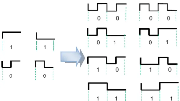
The encoding methods used can be FM0 Baseband (40-640 Kbit /s) or Miller Sub-Carrier (5-320 Kbit / s). In FM0, encoding transitions (from 1 to 0 or 0 to 1) must be at the end of each bit period and additional bit 0 at half the bit period transition is necessary. This is shown in Figure 2.14.
Chapter 2 Safety and RFID Systems
- 29 -
Figure 2.14: FM0 encoding the tag to reader link. On the left), representation of bits 0 and 1. On the right a few possible sequences [EPC2008]
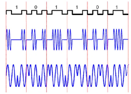
Miller encoding is characterized by the transition that occurs between two zero or two one sequences. As shown in Figure 2.15, a sequence of Miller may have M = 2, 4 or 8 cycles per bit. The M value is present in the query command frame. This parameter is defined by the reader at the beginning of the inventory round.
Figure 2.15: Miller encoding schemes
Figure 2.16 shows how to use Miller encoding, as well as two possible modulations to use this link: ASK or PSK.
- 30 -
Figure 2.16: tag to reader Miller encoding 2.4.1.4 Sessions & inventoried flags
If more than one reader tries to communicate with a single tag at the same time, consistency problems will occur. In this case to allow multiple readers to communicate with a single tag EPC C1 Gen2 standard provides solution support for allowing up to four readers to communicate with the same tag in the same time. This mechanism is called sessions and is based on inventoried flags.
Sessions are useful because they can be used to set the inventoried flags of all tags to a known value. After reading the EPC number of each tag the inventoried flag will be switched. Tag will no longer participate in the current inventory round of this reader. This allows it to communicate with other readers using different sessions.
When the tag is powered on, session flag S0 is set to A, and the other session flags S1 to S3 are set to their previous values (A or B). The SL flag (select flag) is used by the reader to select a tag population before starting an inventory round. The tag modifies its SL flag only when the reader sends the select command before inventory round [EPC 2008].
Chapter 2 Safety and RFID Systems
- 31 -
2.4.1.5 Tag memory
The tags have 4 banks of non-volatile memory as shown in Figure 2.17.
Figure 2.17: Memory banks of a tag [EPC2008].
1. Reserved Memory: contains two 32 bit passwords, one to access to tag and the second to kill the tag. Kill operation permanently disables the tag. The access password allows tag to enter into a state called the secured state.
2. EPC Memory: contains the Cyclic Redundancy Code (CRC), Protocol Control (PC) that contain physical-layer information, and EPC code (Electronic Product Code). During an inventory round the tag backscatters these three codes to the reader.
3. TID Memory: contains the tag identifier.
4. User Memory: this bank is optional and contains specific data. 2.4.1.6 Commands and state machine
There are three basic operations that manage the tag behavior, as shown in Figure 2.18. 1. Select: this command determines which group of tag will respond, i.e. which tags
will answer in the next state.
2. Inventory: identification of tags; in this phase, the reader identifies all tags by their identifier stored in their EPC memory.
3. Access: once the tags have been identified, reader can exchange data with the tags by reading and writing data in their memory.
- 32 - SELECT
INVENTORY
ACCESS
Choose Tag population
Query EPC codes,identify tag
Operate on tag memory
Ready Arbitrate Reply Acknowledged Open Secured
Reader operations
Tag states
State
Killed
Figure 2.18: Commands and state machine
Slot counter: at the beginning of the inventory round the reader sends select command then query command. The tag picks up the Q field in query command frame to generate a random number to preload their slot counter, then every time the tag receive a query rep, it decrements the counter, and when reaching the value of 0 the Tag responds with a 16bit random number.
All operations according to EPC C1 Gen 2 protocol follow the state diagram described in the air-interface specifications in the section 6.3.2.4 of [EPC 2008]. A simplified version of this state diagram following the reader operations is summarized in Figure 2.19.
At the beginning of the inventory round the reader sends the select command then the query command. The tag picks up the Q field found in the query command frame to generate a random number to preload a counter (named slot counter). Then, every time the tag receives a query rep command, it decrements the slot counter. When this counter reaches 0, the Tag answers with a 16 bits random number (RN16_1). This mechanism allows avoiding collision when multiple tags try to communicate simultaneously. Then the following commands sent by the reader will allow to obtain the EPC number and to access to the tag memory.
Chapter 2 Safety and RFID Systems
- 33 -
Figure 2.19: Simplified protocol followed between a reader and a tag [EPC2008] The tag behavior can be described by a finite state machine; this state machine has a large number of states that depend on several parameters, such as slot counter, flags, current state... Using tag state diagram shown in Figure 2.20, we briefly introduce the meanings of each state and transition rules as described in [EPC2008].
- 34 -
Figure 2.20 : Tag state diagram [EPC2008] 1. Ready state:
The initial state when the tag is power up is ready state except in the case the tag is killed. 2. Arbitrate State:
Tags in this state participate in the inventory rounds, and load their slot counter with a random value. If the slot counter is different from zero, the tag still in arbitrate state and counts down this value until it reaches zero. Then the tags go to the reply state. If the tags load the initial slot counter with a zero value, will directly answer to the reader.
Chapter 2 Safety and RFID Systems
- 35 -
3. Reply state:
The tag in this state answers with a 16-bit random number. 4. Acknowledged State:
When the tag is in reply state and the reader sends an Acknowledged command to confirm their response. The tag then transmits its EPC number followed with Identifier called program counter (PC) and CRC that protect the sent frame. The tag remains in this state for a time equals to T1 [EPC2008]. In the absence of any new command from reader, tag will automatically return to arbitrate state. In this state that the reader is able to transition the tag to the Open (or Secured) state allowing access operations such as Read, Write, Lock, and KILL
5. Open state:
When the tag is in acknowledge and the reader sends a request random number (Req_RN) command. If the password stored in reserved memory of the tag equal zero then the tag goes directly to secure state, and if the stored password is different from zero then tag go to open state, and there will be some challenge response between the reader and the tag before the tag go to secure state, this communication is shown in Figure2.21.
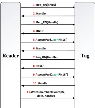
The tag replies by a new 16-bit random number that is called Handle step2, any command requested by the reader must include this random number as a parameter in the command. The reader provides 32-bit password that protects the writing operation. This password consists of two 16-bit sequences, denoted in Figure2.21 as Pw2 and Pw2 code. The reader gets in steps 4 and 8, two random sequences of 16 bits, denoted as RN16 'and RN16". In step 5, the reader applies an XOR operation between the first 16-bit word sequence and the RN16’. Then, it sends the result to the tag for a tag response in step 6, then the reader applies an XOR operation of the remaining 16 bits of the password and the RN16” sequence ", and sends the result to the tag in step 9. The tag recognizes the reception in step 10 by sending a new handle to the reader. Using the latter, the reader can do all access command such as read write kill operation reader step 11.
- 36 - Reader Tag 1. Req_RN(RN16) 2. Handle 3. Req_RN(Handle) 4. RN16' 5.Access(Pwd1 xor RN16') 6. Handle 8.RN16" 9.Access(Pwd2 xor RN16") 10. Handle 11.Write(membank,wordptr, data, handle) 7.Req_RN(Handle)
Figure 2.21: Access protocol of an EPC C1 Gen2 tag 6. Secured state:
The tag transits to secured state after receiving a ReqRN and the Access password is zero. If the tag implements a password, the reader must provide the correct password as described in open state subsection.
7. Kill state:
If the tag receives the kill command with a valid Kill password while it is in the secured state, then it will transit to kill state. The tag will stop any response to reader request and will never be reused.
2.5 Safety and security validation of UHF RFID systems
As we have seen the use of RFID has considerably increased in several critical areas as medical, industrial or military applications. This puts tremendous pressure on designers of RFID systems for security and reliability of critical applications.
Eventual design problems or weaknesses not detected at design time can lead to serious materials or financial damages. Therefore, it is important to evaluate RFID system robustness at design time in order to provide safe and secure systems. The evaluation should tackle both natural and malicious faults which can decrease the system robustness. Due to the inherent heterogeneity and complexity of such systems discussed hereafter, such validation at design time can hardly be performed considering the whole system.
Chapter 2 Safety and RFID Systems
- 37 -
The aim of this work is to present a novel system evaluation platform using emulation and fault injection techniques to provide an additional tool for developers of RFID systems. First, such a tool aims at validating tag hardware architecture taking into account the entire RFID system component interactions. Secondly, it aims at enhancing and validating security-and reliability of the tag once again taking into account the whole RFID system. Faults are emulated using flexible fault injection method. The platform developed in this work enables the efficient evaluation of new hardware implementations of critical security or reliability solutions for UHF RFID tags.
2.5.1 Safety issues
RFID tags are increasingly used into critical applications within harsh environments or for secure applications such identification, counterfeiting protection, etc. However, such low cost systems, initially designed for non-critical applications with a high volume, are not robust by themselves. The behavior of a RFID system must be the same than the one described in the functional specifications, in terms of both performances and functions. The functions are described by the sequences of states of the EPC C1 Gen2 standard [EPC2008]. In these states, the RFID tag performs computation, communication, and store information. The service delivered by the tag is a sequence of information in the form of commands and information requested by Reader. To deliver a correct service regardless its environment, a tag must guarantee the following attributes:
Reliability:
The probability that the tag gives correct outputs within a given time interval [t0,t1]
[Johnson1989]. For this attribute, our objective is to ensure that the tag response is always furnished during an inventory round even in harsh environments or in the presence of attacks.
Availability:
The conditional probability that the tag will correctly work within the time interval [t0, t1], given the system was performing correctly at time t0 [Johnson1989]. It means the tag is ready to be used.
Safety:
The probability that an RFID tag will either perform its functions correctly or will discontinue its functions in a manner that does not disrupt the operation of other tags found in the field of
- 38 -
reader, [Johnson1989]. This is related to the nonoccurrence of catastrophic consequences on the environment.
Integrity:
The absence of improper system alterations, which can appear for example using a malicious reader [Johnson1989].
Maintainability:
The ability to undergo modifications and repairs these modifications by introducing a mechanism of fault tolerance [Johnson 1989].
We will consider an UHF tag delivers a correct service when the service accurately reflects the EPC C1 Gen 2 function requirements. Failures are either because the tag is not well conforming to the standard [EPC2008] or because its architecture does not adequately describe a robust system. In this thesis we will focus on the reliability and the security of tag digital part. We will describe in the following the potential issues in the reliability of digital part of RFID UHF tag.
Since the tag functionalities are based on a correct sequence of states, if a fault occurs then the tag can deviate from its correct state to another. This deviation is called Error. This error can propagate and be transformed to another failures as shown in Figure 2.22 (fault, error and then failure from component A propagates to component B). In Chapter 4 we will analyze in details all fault propagation mechanisms available in the tag architecture.
Figure 2.22: Error propagation in digital system
Figure 2.23 shows the relationship between faults, errors, and failures [Johnson 89]. When a fault occurs, it can cause errors, and errors may propagate to cause service failures.
Chapter 2 Safety and RFID Systems - 39 -
Design Faults
Errors
Failures
Operational
Faults
Physical Information External univers
Figure 2.23: Relationship among faults, errors, and failures
We explain this relationship more in details with an example in the context of an RFID tag. When a tag makes an incorrect state transition, this can be caused by a fault in its design or by a bit flip in one or more registers. This fault can involve a wrong transition of the tag. For example, a transition from the ready state directly to the reply state without passing by the acknowledge state. We can say this is the failure caused by the fault. The reader will detect something wrong and will not consider the tag response. This is the service failure due to the previous error.
2.5.2 Interaction faults that include all external faults RFID Heterogeneity
and complexity:
The main objective of this work is to develop an RFID emulation platform capable of validating both software and hardware solutions and aiming at increasing UHF RFID systems reliability. It must also take into account the problems between tags and effect of a faulty tag on the complete system. Due to the RFID system heterogeneity, this platform should be able to take into account all the system components and all the possible error sources: multiple tags or readers interactions, communication channel errors, disruptions of the environment, radiations, and threats of attack, etc...
As detailed in the previous section, RFID systems are composed of many tags, readers and a middleware. These components consist of analog, digital hardware and software parts. An RFID tag exchanges with a reader via an RF channel, but in the same time this channel can be shared with other tags as illustrated in Figure 2.24. So when validating a tag, one may first validate that the tag fulfills the specifications, and then when a robustness validation is engaged, it is also necessary to consider all system configurations. A faulty tag can impact other system elements but also other elements may disturb the tag under verification. Such a validation may then require to simultaneously consider all elements as explained later on.
- 40 -
Figure 2.24: RFID System with several tags RFID system has several abstraction levels as shown in Figure 2.25
RFID application layer
RFID software layer
RFID hardware layer
RFID Application Layer
RFID Software Layer
RFID Hardware Layer System level model
Algorithm level models
Functional And behavioural level models
Field setup
Communication Protocols
Hardware Models and Physical Devices Figure 2.25: Layers for UHF RFID system modeling
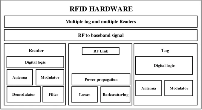
Figure 2.25 shows the complexity of the model for each layer. At the top, the application layer defines the parameters of the hardware component layer that manages the functionality of the whole system. Software layer defines the algorithm to control communication links and data transfers between reader and tags, the communication protocols like collision arbitration, the possible authentication protocol. The hardware layer defines the physical structure of devices and the air interface [EPC2008]. Figure 2.26 shows the hardware layer component structure.
Chapter 2 Safety and RFID Systems - 41 - Digital logic Antenna Demodulator Modulator Filter Reader RF Link Power propagation Losses Backscattering Digital logic Antenna Modulator Tag RF to baseband signal Multiple tag and multiple Readers
RFID HARDWARE
Figure 2.26: Hardware layer structure for UHF RFID system modeling
RFID system improvement needs to check two aspects: the first aspect is the requirement of the system level and the second concerns the hardware level. At system level, functionality and performances verification are required for the “End user” .At hardware level, the designs need to be verified for their conformance to regulations and protocols.
RFID simulation requires a large knowledge on the system and its environment. Simulation can be very time-consuming, in particular if it is necessary to test a lot of environment configurations. It is not possible to meet all RFID component requirements in one simulator. So one alternative to simulation is hardware emulation. First, emulation is much faster than simulation. Secondly, emulation can be used to observe the behavior of an entire system in realistic conditions. This justifies the use of an emulator to validate a complex and heterogeneous system as RFID.
2.6 Conclusion:
In this chapter, we have given a wide overview of RFID technology, by detailing some technical aspects of the structure of RFID system components. Different technical details on reader architecture, tag architecture, and the protocol used in this works [EPC2008] have been detailed in order to better see later implications on dependability issues. The second part of the chapter shows that the use of RFID technology in different critical application requires to study the robustness and the security of such a system. The heterogeneity of the RFID system composed of different technologies (RF, analog, digital hardware, and software) and numerous
- 42 -
components (several tags, reader) communication channels make the robustness enhancement a complex task. For these reasons, we propose an RFID emulator platform that allows us to carry out this task taking into account all the RFID system parameters.
-43-
![Figure 2.19: Simplified protocol followed between a reader and a tag [EPC2008]](https://thumb-eu.123doks.com/thumbv2/123doknet/14409742.704293/35.892.129.769.120.976/figure-simplified-protocol-followed-reader-tag-epc.webp)
![Figure 3.4: Instrumentation based register mask [Civera 2001B]](https://thumb-eu.123doks.com/thumbv2/123doknet/14409742.704293/58.892.237.656.109.472/figure-instrumentation-based-register-mask-civera-b.webp)