IET Electrical Systems in Transportation
Special Issue: Selected Papers from the 2019 IEEE Vehicle Power
and Propulsion Conference (VPPC)
Energy management strategy to optimise
regenerative braking in a hybrid dual-mode
locomotive
ISSN 2042-9738 Received on 14th May 2020 Revised 15th August 2020 Accepted on 18th August 2020 E-First on 23rd November 2020 doi: 10.1049/iet-est.2020.0070 www.ietdl.orgDiana Sofía Mendoza
1, Javier Solano
1, Loïc Boulon
21Universidad Industrial de Santander (UIS), Bucaramanga, Colombia 2Université du Québec à Trois-Rivières, Canada
E-mail: jesolano@uis.edu.co
Abstract: This study proposes an energy management strategy (EMS) for a dual-mode hybrid locomotive equipped with a fuel
cell, supercapacitors, and batteries, and intermittent access to an electrified overhead catenary. It is inspired by the Ragone plot and does not consider information or predictions of future load consumption. It aims to reduce a cost function that considers the cost of hydrogen, the electricity consumed from the network, and the energy sources' degradation. The EMS focuses on maximising the energy recovered during braking. The study introduces a methodology to tune the EMS parameters. Two study cases are used to evaluate the EMS. In the evaluation driving profile, typical for a French freight train, the braking energy is around 12.8% of the total energy. With the proposed EMS, the energy recovered is around 99.8% of the total braking energy. A second EMS not oriented to reduce the energy in the braking resistor is also evaluated. The energy recovered with this strategy is around 91.5% of the total braking energy. The global energy reduction is around 1.1% compared with the second EMS and 12.8% without energy recovering. These results show a real opportunity to increase the energy recovered during braking.
1 Introduction
A dual-mode locomotive has a common drivetrain that operates on not- and electrified tracks. It allows driving a locomotive in a partially electrified railway. Considering the high cost of the network electrification, this is a good compromise to reduce energy consumption in rail transport [1]. In this regard, fuel cell (FC) locomotives are considered as a great alternative to moving away from locomotives using diesel engines [2–8]. FCs are not reversible and the responsiveness of the gas supply limits their response. Therefore, the time constants as obtained from step responses of electrical power are rather, pointing to a rather low bandwidth and a low-access speed [9]. For these reasons, the FC cannot be considered as a unique source for electrical locomotives. Supercapacitors (SCs) and batteries offer high efficiency and a high speed of access to electrical energy. They are, therefore, an ideal complement to the FC in hybrid electric locomotives [10–13]. Control of FC, and in general, hybrid locomotives is a very complex problem. For the sake of ease, it can be subdivided into two independent problems: to define driving strategies based on optimal speed trajectories and to determine power distribution among the available sources.
Many research studies aim to define optimal speed trajectories using analytical techniques such as Pontryagin's minimum principle [14–16] or numerical methods such as dynamic programming [17–19]. These techniques require a perfect knowledge of the operating conditions during a mission. This could be true for a great number of locomotives periodically running on the same track according to a strict timetable.
Methodologies to determine optimal train speed profiles are proposed in both theory and applications, but they are complicated and complex to achieve. In real operation conditions, the train may not always follow the planned schedule. It will not arrive at or depart from the station on time because of unpredictable traffic conditions, unplanned stops, unsteady driving behaviours, passenger demand variations, infrastructure failures, or even the willingness of the train driver to follow the recommended speed profile [20–22].
As these optimal speed profiles are theoretical but difficult to follow, then real-time operation adjustment is recommended [23]. Therefore, developing on-line algorithms that consider dynamic
situations such as traffic in the path ahead may be more applicable for practical purposes [24]. Heuristic solutions such as fuzzy logic [24, 25] or genetic algorithms [26, 27] are often proposed to define the optimal speed trajectory references.
Once the speed profile is determined using the dynamical model of the train, braking and traction force profiles are computed. These are used to compute power profiles on the locomotive power bus. The new challenge consists of defining the power and energy distribution among the available sources. Energy management strategies (EMSs) are designed to determine power and energy distributions among the energy sources for a given bus power profile. The solutions aim to minimise a multi-objective cost function while respecting static and dynamic constraints to limit the power, currents, and the state-of-charge (SOC) of the energy storage sources.
As stated before, in real operation conditions, it is not easy to predict power profiles, and then real-time EMSs are more than desirable. The proposed EMS should guarantee good performances even without knowledge of train speed and power profiles. Rule-based approaches lean on human experience to design EMS algorithms to define the power distribution. Compared with other approaches, these strategies are intuitive and easier to implement. Many research studies propose rule-based methodologies to determine the power distribution in hybrid trains [13, 28–30].
The energy dissipated during train braking can be very high. In some urban rail systems, this value can be up to 50% of the net traction energy [31, 32]. Thus, it is not surprising that one of the most significant opportunities to reduce the energy consumption in trains is to perform an efficient use of energy regenerated during braking. Regenerative braking can be used by other trains, but it is only possible if, at the same time, a train is accelerating and another is braking, then a sophisticated, coordinated train control and time-scheduling is required [33–35]. The braking energy can be supplied to the power system using reversible substations that require a very high investment.
Embedded energy storage sources such as SCs or batteries are used to perform recovery braking. They are a more viable alternative to recover energy during braking. This option is similar to the one used in an application with a high-start/stop frequency such as elevators driven by synchronous machines [36, 37]. These embedded sources present additional advantages such as reduction
of peak power demand, reduction of energy losses in the catenary, and a certain degree of autonomy for catenary-free services [31].
Most of the works published in energy recovery using embedded sources focus on metro trains and tramways, considering their frequent start/stops. Most of these research studies estimate a reduction in total energy consumption around 12–35% when using SC. Simulation results reported in the literature show reduction of 33% for a metro line in Brussels [38], 24% for a metro line in Madrid [39], 25% for a tramway in Mannheim [40], or 30% for a Blackpool tramway [41] are reported in the literature. The research presented in [21], oriented to freight trains, shows that using a storage unit to enable regenerative braking reduces up to 25% of the total energy.
Experimental research has pointed out that SCs can recover most of the energy recovered in braking [29, 30, 42]. An experimental study suggests a reduction of around 16% energy savings in a tramway in Paris [43]. Moreover, experimental tests performed so far on a light railway vehicle prototype of Bombardier Transportation have highlighted that the energy saved using SCs could be ≃30% [44].
This work aims to solve the problem proposed in the IEEE Vehicular Technology Society (VTS) motor vehicles challenge 2019 – energy management of a dual-mode locomotive [45]. It consists of proposing an EMS for a dual-mode locomotive equipped with a FC, SCs, batteries, and access to an electrified overhead catenary. The solution must minimise a cost function that considers the consumption of the electricity network, the consumption of hydrogen, the lifetime of the FC, and the lifetime of energy sources. The solutions to the challenge must respect an additional constraint: no previous knowledge of the speed or power profile is allowed to compute the power distribution.
This paper proposes an extended version of the research presented in [46], which was the best solution submitted to the IEEE VTS Motor Vehicles Challenge 2019. This EMS has new objectives such as maximising the energy recovered during braking, which can represent an important part of the total energy losses of the train. The paper is organised as follows: Section 2 introduces the global EMS. Then it presents the local EMSs for the FC, batteries, SCs, and DC bus capacitor. Section 3 presents simulation results, and Section 4 presents the conclusions.
2 Model and EMS of the dual-mode locomotive
The considered hybrid locomotive can be powered by a nreversible DC overhead line through a pantograph or using an on-board FC with batteries and SCs. The sources are connected to the DC bus using power converters. Fig. 1 presents the schematic of the dual-mode locomotive.The proposed EMS defines current references for the FC system
ifcS(t), the battery system ibS(t), the SC system iscS(t), and the
braking resistor ibr(t). The current supplied by the pantograph
ipant(t), when available, and the current supplied to/by the DC bus
capacitor ibus depend on the DC bus capacitor voltage which can be
indirectly controlled. The current consumed by the motor drives
itr(t) and the ancillary iaux(t) is not known a priori.
The current distribution between the sources and loads, at the DC bus level, respects the balance defined in (1)
itr(t) + iaux(t) + ibus(t) − ipant(t)
= ifcS(t) + ibS(t) + iscS(t) + ibr(t) (1)
2.1 Constraints
The solutions must respect constraints in the sources powers, currents, voltages, and SOC. One additional challenge to consider is that the EMS references are given at the DC bus level, after the power converters, but most of the constraints are given in the terminals of each source before the power converters. These constraints are defined for the voltage and current in the terminals of the FC ifc(t), vfc(t), the battery ib(t), vb(t) and the SC isc(t), vsc(t).
The batteries and SCs SOCs SOCb, SOCsc are also constrained. Additional constraints are given for the power supplied by the power converters pscS(t), pfcS(t), pbS(t), and pbr(t).
The restrictions for a generic source k and its power converter
ks are presented below
Vkmin< vkt < Vkmax (2) SOCkmin< SOCkt < SOCkmax (3)
Ikmin< ikt < Ikmax (4) dIk dtmin< d ik dt t < dikdtmax (5) Pksmin< pkst < Pksmax (6) 2.2 Cost function
The viable solutions are evaluated and compared using a multi-objective function €tot composed of six cost functions to minimise
[1]
(i) The hydrogen consumption €H2. It depends on the H2 mass flow, which at its time depends on the current supplied by the FC
ϵH2(t) = H1.102 −cost3
∫
0 tm˙H2(t)dt (7) with m˙H2(t) the hydrogen mass flow (g/s) and H2 −cost the hydrogen cost per unit of hydrogen mass €/kg .
(ii) The FC degradation €fc. The FC degradation function Δfc(t)
depends on the power operation pfc(t) and the start number Nstart of
the FC [47, 48] Δfc(t) = NstartΔstart(t) +
∫
0 t δ(t)dt (8) δ(t) = δ0 3600 1 +Pfc2α−rat pfc(t) − Pfc−rat 2 (9)with Δstart(t) the start-stop degradation coefficient, δ0 and α load coefficients, and Pfc−rat the rated power of the FC (W). The
operational cost of the FC can then be deduced from Δfc(t)
ϵfc(t) = Pfc−rat
1.103FCcostΔfc(t) (10) 1. ith FCcost the FC cost per unit of power €/kW .
2. iii) The SC degradation €sc. The degradation function of the
SCs Δsc(t) is calculated by the ratio between the use time tuse
and the expected lifetime
ΔSC(t) =30.10tuse3 (11) 3. The operational cost of the SCs can then be deduced from
Δsc(t) Fig. 1 Structural scheme of the studied locomotive
ϵsc(t) = Esc−ratSCcostΔsc(t) (12)
1. ith Esc−rat the rated energy of the SCs (kWh) and SCcost the
SCs cost per unit of energy (€/kWh).
2. iv) The batteries degradation €bat. The battery degradation
function Δb(t) depends on the SOC with f SOCb and power
dynamics with g ib [49] Δb(t) = 3600.15 ⋅ 101 3⋅ Q b−rat
∫
0 t f SOCb ⋅ g ib ⋅ ib(t) dt (13) 3. with Qb−rat and ib(t), respectively, the rated capacity (Ah) andthe current (A) of the battery. The operational cost of the battery can then be calculated from Δb(t)
ϵb(t) = Eb−ratBcostΔb(t) (14)
ith Eb−rat the rated energy of the battery (kWh) and Bcost the battery
cost per unit of energy €/kWh .
(v) The electricity consumed from the network €net
ϵnet(t) = 3600.1.10Ncost 6
∫
0 tpline(t)dt (15)
1. ith pline(t) the instantaneous power (W) delivered by the DC
line of the electricity network and Ncost the cost of the
electricity network per unit of energy e/MWh , which takes into account the public electricity network tariffs.
2. vi) The battery and SC recharge after the cycle €sust
ϵsust(t) =1.10Ncost3ηdc−b−avg⋅ Eb−end
+ηdc−sc−avg⋅ Esc−end
(16)
1. ith ηdc−b−avg and ηdc−sc−avg the average value of the efficiency
maps of the boost choppers; and Eb−end and Esc−end the energy
stored of the battery and SCs at the end of the simulation (kWh). The sustainability cost €sust can be negative if the final
SOC of the SC or batteries is higher than the initial.
2.3 Solution
Considering the characteristics and constraints of each energy source, and inspired on the Ragone plot illustrated in Fig. 2, a rule-based global EMS is proposed and implemented. The FC is the primary energy source embedded in the dual-mode locomotive. Together with the pantograph, when available, they must supply the total energy consumed by the traction system. However, during braking, the FC current is reduced to limit the energy dissipated in the braking resistor. The pantograph is an interesting source in terms of power and energy, but the EMS has to consider its intermittent availability (dual-mode EMS). The batteries are characterised by a good compromise between power and energy. They can be used to provide energy to the load and in regenerative braking. The SC, as the main power source of the locomotive, is used to balance the current balance defined in (1).
The guidelines listed below are proposed to define the EMS rules.
• The FC and pantograph recharge the batteries. • The batteries regulate the SC SOC.
• The SC regulates the DC bus voltage. • The braking resistor use must be avoided.
Compared with the previous EMS presented in [46], this one is oriented to reduce the energy consumed in the braking resistor. Two sets of rules are used to reach this objective. The first one
rapidly decreases the output power of the FC when braking is detected. The second set of rules allows using the DC bus capacitor to store part of the braking energy. The local EMSs allow achieving the proposed objectives presented in the next subsections.
2.4 FC local EMS
The FC is the primary energy source embedded in the locomotive. As the FC has strong constraints to fast changes in the supplied current, its local EMS does not consider information about the current consumed by the loads or provided by the sources. The degradation is fast accelerated when turning the FC off and on again.
In normal operation, the FC's only objective is to regulate the batteries SOC. The reference for its current ifcSref will increase with the reduction on the batteries measured SOC SOCb compared with
a static reference SOCbref. Here, this reference is constant and considered an optimisation parameter. This SOC regulation is performed by a proportional controller with Kfc gain.
The proportional controller is used to define the FC current reference ifcref considering the error between the batteries SOC SOCb and its reference SOCbref. Fig. 1 illustrates ifcref for three different values of Kfc. Here, Kfc1 is the maximal and Kfc3 is the minimal feasible value for the controller gain.
A second operation mode is considered when the locomotive is braking fast. This is when a negative acceleration aloco goes below
a predetermined value amin. In this operation mode, regenerative
braking is activated, and the batteries and SC are expected to operate at maximal recharge current. To avoid, or at least reduce, the dissipation of energy in the braking resistor, during strong braking, the FC current reference is fast reduced to a low value
Ifclow.
Additionally, due to the high degradation cost, the EMS must prevent the FC to turn off as possible, and the current reference is then limited by a lower bound Ifclow. Finally, the FC current must respect the static Ifcmax and dynamic dIfcmax limits defined by the characteristics of the source (Fig. 3).
The FC reference current is computed using Algorithm 1 (Fig. 4).
Fig. 2 Ragone plot and energy flow between the locomotive's sources
Fig. 3 Static reference for if cre f
2.5 Batteries local EMS
The batteries transfer energy from the FC to the SCs. This condition is mandatory to ensure the SC system can operate as the main power source. The batteries do not have the same dynamic limitations as the FC and can be used as a power source and in less degree for regenerative braking. The reference for its current ibref increases if the SC SOC SOCsc decreases compared with a
dynamic reference SOCscref. This control is performed using a proportional controller with Kb gain and is shown in Fig. 5. Here,
Kb1 is the maximal and Kb3 is the minimal feasible value for the controller gain.
Several research studies suggest defining a dynamic reference for the SC SOC considering the speed and kinetic energy of the vehicle [28–30, 50]. The reference for the SC SOC SOCscref depends on the train speed: at maximal speed Velmax the SCs are
discharged to a minimal SOC SOCscVelmax: this enables enough place to store the energy recovered by the regenerative braking hence minimising the risk of using the braking resistor. When the locomotive is stopped, the ultracapacitors (UCs) are recharged until a maximal SOC SOCscVel0, and this enables enough energy in the SC to support accelerating the train.
A proportional controller is used to define SOCscref: a decreasing function of the train speed, which is directly related to the kinetic energy of the train. This controller is illustrated in Fig. 6. The battery's local EMS does not consider the power consumed by the load or provided by the other sources.
The batteries reference current is computed using Algorithm 2 (Fig. 7).
2.6 SCs local EMS
The SC system balances the currents consumed by the locomotive and provided by the FC system and batteries system. Additionally, the SC system regulates the DC bus voltage level, supplying a
regulation current ibus. The algorithm to define this current is
presented in the next subsection.
As the SCs balance the currents supplied and consumed by the loads, the SC EMS only uses currents as inputs. Additionally, and compared with the FC and batteries, the UC system reference current iscSref is the only reference directly computed at the DC bus level side.
The UC system reference current is computed using Algorithm 3 (Fig. 8).
2.7 Braking resistor local EMS
A braking resistor is implemented in the locomotive. It is modelled as a perfectly controllable current source [1]. The braking resistor use must be minimised. However, during braking, the excess of power that cannot be stored in the SC and batteries should be sent to the braking resistor to avoid overvoltages in the DC bus. This local EMS has no parameters. The braking resistor reference current ibrref is computed using Algorithm 4 (Fig. 9).
2.8 DC bus EMS
The DC bus voltage local EMS depends on the presence or not of the pantograph. The main difference between the two operation modes is the reference for the DC bus operation voltage. The DC bus voltage level depends on the energy supplied to/from the DC bus capacitor. A regulation current ibus(t) can be supplied to/from
the capacitor to control the DC bus voltage. As the capacitor
Fig. 4 Algorithm 1: FC local EMS
Fig. 5 Reference for ibre f(t)
Fig. 6 Reference for SOCscre f
Fig. 7 Algorithm 2: batteries local EMS
Fig. 8 Algorithm 3: SCs local EMS
Fig. 9 Algorithm 4: braking resistor local EMS
current depends on the balance shown in (1), and the DC bus capacitor has no power converter, this current has to be indirectly controlled.
To keep the DC bus voltage constant, ibus(t) in (1) is set to zero.
Then the UCs balance the current supplied by the sources and consumed by the loads. To increase/decrease the DC bus voltage, the UCs provide more/less current than required in this balance. This excess of current ibus(t) is supplied by the DC bus capacitor
and increases/decreases the DC bus voltage.
A proportional controller is used to determine the reference value for ibus(t). The input of this controller is the difference between the DC bus voltage reference vbusref and measure vbus(t).
With or without pantograph, only one proportional controller with
Kbus gain is implemented. This controller is illustrated in Fig. 10
2.8.1 Mode pantograph ON: The pantograph is a secondary
source that can be eventually used to supply power to recharge the batteries. The energy from the pantograph cannot be directly controlled. This is indirectly done by controlling the DC bus voltage, as explained before. If the DC bus voltage is lower than the pantograph voltage, the power flows from the network to the locomotive. If the DC bus voltage has the same magnitude as the pantograph, the flow of power will be zero.
If the batteries are charged, the DC bus voltage reference vbusref is set to the same value of the pantograph voltage Vline. When the
batteries are discharged, and their SOC goes beyond a low boundary SOCblow, the DC bus voltage reference vbusref is set to a lower value, to consume power from the pantograph. In this paper, the pantograph supplies a constant current Irech.
2.8.2 Mode pantograph OFF: The DC bus capacitor can store a
limited amount of energy during strong braking. When the train is in normal operation vbusref is set to a low value Vlow. This voltage should respect the restrictions of the DC bus.
When strong braking is detected, vbusref is set to a high value
Vhigh. This condition allows storing some of the braking energy in the capacitor. The DC bus voltage regulation current reference is computed using Algorithm 5 (see Fig. 11).
2.9 Dual-mode EMS and parameters
Fig. 12 illustrates the global EMS for the dual-mode locomotive. This strategy requires defining two sets of parameters. The first subset of parameters is related to the characteristics and constraints of sources, e.g. the maximal current. The second set of parameters is related to the local EMS for each source, e.g. the proportional controllers' gains.
The first subset has nine parameters: the maximal FC current
Ifcmax, the maximal change of the FC current in a computing period dIfcmax, the maximal batteries current Ibattmax, the minimal batteries current Ibattmin, the maximal SC current, the minimal SC current, the maximal locomotive speed Velmax, the pantograph resistance Rpanto,
and the network voltage Vline.
The subset related to the local EMS has 14 parameters: three for the local FC EMS, seven for the local DC bus EMS, three for the local batteries EMS, and the acceleration to identify strong braking
amin.
The local FC EMS requires the proportional gain Kfc, the minimal FC current Ifclow, and the batteries SOC reference SOCbatref. The local batteries EMS requires the SC SOC reference at maximal locomotive speed SOCscVelmax, the SC SOC reference
Fig. 10 Reference for ibusre f
Fig. 11 Algorithm 5: local DC bus capacitor EMS
Fig. 12 Dual-mode locomotive EMS
when the locomotive stopped SOCscVel0 and the proportional gain
Kb.
The local DC bus EMS requires the maximal Ibushigh and minimal Ibuslow bus current, the constant pantograph current Irech, the proportional gain Kbus, the batteries SOC reference for start pantograph recharge SOCblow, and the voltage references for normal operation Vlow and strong braking without pantograph Vhigh.
2.10 EMS parameters tuning
For any load profile, an optimal set of EMS parameters should minimise the cost function presented in Section 2.2 and respect the constraints defined in Section 2.1. With all the EMS parameters listed, the next challenge is to identify their optimal values. Some authors use heuristic or analytical optimisation techniques to determine sets of optimal EMS parameters. These sets can be optimal for a determined profile but not optimal for every possible profile. This tuning process strongly depends on the problem specifications. However, optimising any EMS for these evaluation profiles does not guarantee optimally for an unknown scoring profile.
We propose in this paper a simple methodology to determine the EMS parameters. This methodology is inspired by the experimental method [51, 52] and the Taguchi approach [53]. It is a systematic approach to understand how EMS parameters affect the system dynamics and cost functions. The proposed method consists of evaluating in a feasible space of solutions several sets of parameters.
The main set of parameters WEMS is composed of subsets of feasible solutions for each parameter
WEMS= {w1, w2, w3, …, wm}
Each parameter subset wi is composed of xi levels (feasible solutions). These subsets are defined using the following methodology.
First, boundaries for each of the EMS parameters are defined. It is necessary to carefully select lower and higher limits (wilow and
wihigh) to generate a feasible search space.
Then the xi levels for each parameter are determined. This number could be different for each parameter. The subsets with feasible values are generated as illustrated below
wi→ wi1, wi2, wi3, …, win feasible solutions range
with wi1= wilow and win= wihigh.
Finally, a full factorial experiment is performed. It is an exhaustive research of all the feasible combinations of levels for each parameter (solutions). This experiment requires SN simulations given by
SN=
∏
i = 1 mxi
where m is the total number of parameters.
The computational cost of this method could be prohibitive when the number of solutions increases. Simultaneous optimisation of all the parameters will exponentially increase the number of solutions. An alternative iterative algorithm is used to reduce the computational cost. The optimisable parameters are divided into two groups. In a first step, the FC local EMS and batteries local EMS are simultaneously optimised with the other parameters constant. After this, in a second step, the DC bus local EMS parameters are optimised, keeping the other parameters constant. This process is repeated until the best solution between successive iterations has no significant improvement. The output of this methodology can be considered as a set of near-optimal parameters for the proposed EMS.
3 Validation results
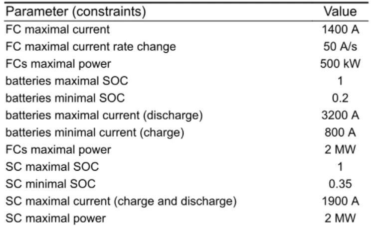
The proposed EMS is evaluated by simulations using the dualmode locomotive model, and speed and bus power profiles provided by the IEEE VTS Motor Vehicles Challenge 2019 organisers [1]. The problem constraints are presented in Table 1.
Following the rules and the IEEE VTS Motor Vehicles Challenge's philosophy, the three profiles presented in [1] are used to tune the EMS. This tuning is performed following the methodology presented in Section 2.10. A fourth power profile, provided by the organisers of the IEEE VTS Motor Vehicles Challenge 2020, is used to evaluate the EMS. This profile was unknown to the challenge participants and is not used to tune the EMS.
The scoring profiles are illustrated in Fig. 13. All the solutions must respect the constraints in Table 2. Two study cases are presented, the two cases use the same sources model and power profiles, but they consider two different hydrogen consumption models illustrated in Fig. 14.
Table 1 Constraints
Parameter (constraints) Value
FC maximal current 1400 A
FC maximal current rate change 50 A/s
FCs maximal power 500 kW
batteries maximal SOC 1
batteries minimal SOC 0.2
batteries maximal current (discharge) 3200 A batteries minimal current (charge) 800 A
FCs maximal power 2 MW
SC maximal SOC 1
SC minimal SOC 0.35
SC maximal current (charge and discharge) 1900 A
SC maximal power 2 MW
Fig. 13 Traction + auxiliaries power and speed profile
Table 2 Results
Variables Original EMS New EMS
recovered braking energy, % 91.5 99.8 energy consumption reduction, % 11.7 12.8
Fig. 14 H2 flow models
Each of the considered study cases has a specific purpose: the first evaluation aims to highlight the principal contributions of the EMS, compared with the EMS proposed in [46]. The second evaluation's main objective is to demonstrate that the proposed strategy can almost eliminate the necessity to use the braking resistor and then maximise the energy recovered using regenerative braking.
3.1 First H2 consumption model
For the first validation scenario, the cost function defined in [1] is used. The simulation results are compared with that proposed by Mendoza et al. [46]. These results are not optimal, but they were the best solution submitted to the IEEE VTS Motor Vehicles Challenge 2019.
The methodology in Section 2.10 is used to find a set of parameters of the EMS. Fig. 15 presents the best results submitted to the IEEE VTS Motors Vehicles Challenge 2019. Fig. 6 illustrates the results obtained with the new EMS. The total cost is
€6.03 for the original EMS and €1.21 for the new EMS. The original EMS has a braking resistor energy consumption of 3.03 kWh. The improved strategy has a braking resistor energy consumption of 2.85 kWh.
In both EMSs, the FC starts operating in a high-power zone to recharge the batteries until the desired SOC. After this, the FC operates in a high-efficiency zone, keeping the batteries charged. In the new EMS, when strong braking is detected, the FC power decreases its output power, at the maximal rate, to reduce the necessity to use the braking resistor. Eliminating this waste of energy is, however, only possible when the FC operates in a high-efficiency zone. In this specific study case, after the first hour needed to recharge the batteries. The high difference observed in the total cost obtained with the two EMSs is mainly due to the sustainability cost, because the energy stored in the batteries at the end of the mission is much higher in the new strategy.
It has been demonstrated with this first case study that a considerable reduction in the total cost of the mission can be obtained using the new EMS. The work presented in Jia et al. [54] proposes a rule-based EMS where the FC operates supplying high power all the time. This power is used to recharge the SC and batteries to their maximal SOC. In this strategy, the total cost is even negative −€4.69.
In the scoring cycle, the locomotive is driven for 70.86 km during more than 2 h. The locomotive and its ancillaries consume around 260 kWh. Using the model provided by Lhomme et al. [1], the hydrogen consumption is 88 g with the proposed EMS, and 90 and 178 for the EMS in [46, 54], respectively. These results are not realistic: one gram of hydrogen stores about 0.04 kWh. A FC with 50% (high) average efficiency consumes around 50 g H2 to produce one electrical kWh. Around 13 kg of H2 are needed to supply the energy consumed by the locomotive. Additional H2 is required to provide the system energy losses and to recharge the SC and batteries. As the H2 consumption is underestimated, the equivalent cost of energy produced by the FC is very low compared with the expected in a realistic FC. With this consumption model, it is better to use the FC to produce energy to recharge the batteries and SC. For this reason, the solutions presented by Jia et al. [54] or Mendoza et al. [46] operate the FC close to the maximal power and were the best solutions to the IEEE VTS Motor Vehicles Challenge 2019.
3.2 Second H2 consumption model
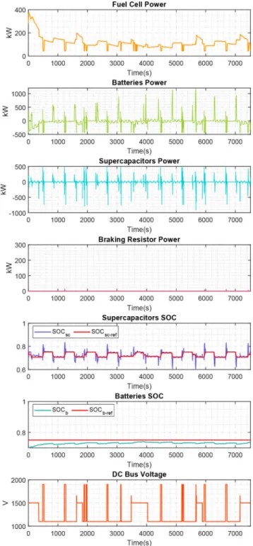
A second evaluation of the EMS is performed using the same speed and bus power profile but a different H2 consumption model. The new model is inspired by that proposed in IEEE VTS Motors Vehicles Challenge 2017 (Fig. 16). The methodology proposed in Section 2.10 is used to find a set of parameters of the proposed EMS. Fig. 17 illustrates the results obtained with the new H2 consumption model. The new total cost is €57.56 and 14 kg of H2. In this case, the FC operates in a high-power zone to recharge the batteries until the desired SOC. However, the desired SOC with this strategy is much lower than the previous EMS, and the FC will work in this operation mode only for a few minutes compared with 1 h in the previous study case. When strong braking is detected, the FC power decreases at its minimal power at the maximal rate, to reduce the necessity to use the braking resistor. As the FC does not operate a long time in high-power mode, the energy dissipated in the braking resistor is almost eliminated. The proposed DC bus voltage regulation strategy allows recovering part of the braking energy. The energy consumed in the braking resistor is 0.064 kWh, around 50 times less than the energy dissipated with the previous EMS. This reduction is illustrated in Fig. 18. Table 2 summarises the results obtained with the new strategy and compare it with the results obtained with the old strategy, in terms of recovery of braking energy. It is demonstrated here that using this EMS, the energy recovered in braking can be improved. Considering the efficiency of the FC and the energy consumed by the load, the optimal consumption should be around 13 kg of H2. These results confirm that by using the proposed EMS, and the results are close to the expected optimal values.
Fig. 15 IEEE VTS Motors Vehicles Challenge 2019 best solution
4 Conclusion
This paper proposed an EMS to define power distribution references in a dual-mode locomotive equipped with a FC system, a SC system, batteries, a braking resistor, and intermittent access to a DC electrified overhead line. The solution proposed is a rule-based approach inspired on the Ragone plot. The proposed EMS is relatively simple and conceived to be intuitive and easy to implement. The paper also introduces a simple methodology to tune the EMS parameters. As illustrated with the two study cases, the parameters of the EMS strongly depends on the problem characteristics, such as the price of the electricity from the network or the hydrogen.
As the EMS has a low number of parameters, future research can focus on improving the tuning procedure, using optimisation techniques such as genetic algorithms. New research should also focus on including global positioning system information in the EMS: anticipating potential energy gains at negative slope profiles, the SC and batteries SOC references can be modified to enable
recovering this energy. Even if the results are not optimal, this strategy is straightforward to implement and could be easily adapted to be used in other FC–UC–battery hybrid sources.
In the study case, up to 99.8% of the braking energy in a freight train can be recovered. This saving represents a 8.3% increase in the energy recovered and 1.1% of the total energy consumption, compared with the work presented in [46]. The global energy consumption reduction in these trains is estimated by 12.8% using UC. These results suggest that in applications with a higher frequency of start/stops like metro trains or tramways, this reduction could be even more than 30%. This demonstrates that using a well-designed EMS, the energy recovered during braking in embedded energy sources can be highly increased and almost eliminate the necessity to dissipate energy in braking resistors.
5 Acknowledgment
This research was partially funded by the Emerging Leaders in the Americas Program (ELAP) from the Government of Canada.
Fig. 16 IEEE VTS Motors Vehicles Challenge 2019 – new EMS Fig. 17 New H2 consumption model – new EMS
6 References
[1] Lhomme, W., Letrouve, T., Boulon, L., et al.: ‘IEEE VTS Motor Vehicles Challenge 2019-energy management of a dual-mode locomotive’. 2018 IEEE Vehicle Power and Propulsion Conf. (VPPC), Chicago, IL, USA, 2018, pp. 1– 6
[2] Din, T., Hillmansen, S.: ‘Energy consumption and carbon dioxide emissions analysis for a concept design of a hydrogen hybrid railway vehicle’, IET Electr. Syst. Transp., 2018, 8, (2), pp. 112–121
[3] Hoffrichter, A., Hillmansen, S., Roberts, C.: ‘Conceptual propulsion system design for a hydrogen-powered regional train’, IET Electr. Syst. Transp., 2016, 6, (2), pp. 56–66
[4] Hong, Z., Li, Q., Han, Y., et al.: ‘An energy management strategy based on dynamic power factor for fuel cell/battery hybrid locomotive’, Int. J. Hydrog. Energy, 2018, 43, (6), pp. 3261–3272
[5] Li, Q., Wang, T., Dai, C., et al.: ‘Power management strategy based on adaptive droop control for a fuel cell–battery–supercapacitor hybrid tramway’, IEEE Trans. Veh. Technol., 2017, 67, (7), pp. 5658–5670 [6] Sarma, U., Ganguly, S.: ‘Design optimisation for component sizing using
multiobjective particle swarm optimisation and control of PEM fuel cell– battery hybrid energy system for locomotive application’, IET Electr. Syst. Transp., 2019, 10, pp. 52–61
[7] Yoneyama, T., Yamamoto, T., Kondo, K., et al.: ‘Fuel cell powered railway vehicle and experimental test results’. 2007 European Conf. on Power Electronics and Applications, 2007, pp. 1–10
[8] Yedavalli, K., Guo, L., Zinger, D.S.: ‘Simple control system for a switcher locomotive hybrid fuel cell power system’, IEEE Trans. Ind. Appl., 2011, 47, (6), pp. 2384–2390
[9] Strunz, K., Brock, E.K.: ‘Stochastic energy source access management: infrastructure-integrative modular plant for sustainable hydrogen-electric cogeneration’, Int. J. Hydrog. Energy, 2006, 31, (9), pp. 1129–1141 [10] Baert, J., Jemei, S., Chamagne, D., et al.: ‘Energetic macroscopic
representation of a hybrid electric locomotive and experimental characterization of nickel–cadmium battery cells’. 15th European Conf. on Power Electronics and Applications (EPE), 2013, pp. 1–10
[11] Jaafar, A., Akli, C.R., Sareni, B., et al.: ‘Sizing and energy management of a hybrid locomotive based on flywheel and accumulators’, IEEE Trans. Veh. Technol., 2009, 58, (8), pp. 3947–3958
[12] Strunz, K., Louie, H.: ‘Cache energy control for storage: power system integration and education based on analogies derived from computer engineering’, IEEE Trans. Power Syst., 2009, 24, (1), pp. 12–19
[13] Radu, P.V., Szelag, A., Steczek, M.: ‘On-board energy storage devices with supercapacitors for metro trains-case study analysis of application effectiveness’, Energies, 2019, 12, (7), p. 1291
[14] Khmelnitsky, E.: ‘On an optimal control problem of train operation’, IEEE Trans. Autom. Control, 2000, 45, (7), pp. 1257–1266
[15] Albrecht, A., Howlett, P., Pudney, P., et al.: ‘The key principles of optimal train control—part 1: formulation of the model, strategies of optimal type, evolutionary lines, location of optimal switching points’, Transp. Res. B, Methodol., 2016, 94, pp. 482–508
[16] Liu, R., Golovitcher, I.M.: ‘Energy-efficient operation of rail vehicles’, Transp. Res. A, Policy Pract., 2003, 37, (10), pp. 917–932
[17] Franke, R., Terwiesch, P., Meyer, M.: ‘An algorithm for the optimal control of the driving of trains’, Proc. IEEE Conf. on Decision and Control, 2000, 3, pp. 2123–2128
[18] Sorrentino, M., Serge Agbli, K., Hissel, D., et al.: ‘Application of dynamic programming to optimal energy management of grid-independent hybrid railcars’. Proc. Inst. Mech. Eng. F, J. Rail Rapid Transit, 2020, p. 0954409720920080
[19] Haahr, J.T., Pisinger, D., Sabbaghian, M.: ‘A dynamic programming approach for optimizing train speed profiles with speed restrictions and passage points’, Transp. Res. B, Methodol., 2017, 99, pp. 167–182
[20] Yin, J., Tang, T., Yang, L., et al.: ‘Energy-efficient metro train rescheduling with uncertain time-variant passenger demands: an approximate dynamic programming approach’, Transp. Res. B, Methodol., 2016, 91, pp. 178–210 [21] Lanneluc, C., Pouget, J., Poline, M., et al.: ‘Optimal energy management of a
hybrid train: focus on saving braking energy’. Proc. 2017 IEEE Vehicle Power and Propulsion Conf. (VPPC 2017), Belfort, France, 2017, pp. 1–6 [22] Yang, Z., Yang, Z., Xia, H., et al.: ‘Brake voltage following control of
supercapacitor-based energy storage systems in metro considering train operation state’, IEEE Trans. Ind. Electron., 2018, 65, (8), pp. 6751–6761 [23] Gu, Q., Tang, T., Cao, F., et al.: ‘Energy-efficient train operation in urban
rail’, IEEE Trans. Intell. Transp. Syst., 2014, 15, (3), pp. 1216–1233 [24] Saadat, M., Esfahanian, M., Saket, M.H.: ‘Energy-efficient operation of diesel
electric locomotives using ahead path data’, Control Eng. Pract., 2016, 46, pp. 85–93
[25] Cucala, A.P., Fernández, A., Sicre, C., et al.: ‘Fuzzy optimal schedule of high speed train operation to minimize energy consumption with uncertain delays and drivers behavioral response’, Eng. Appl. Artif. Intell., 2012, 25, (8), pp. 1548–1557
[26] Bocharnikov, Y., Tobias, A., Roberts, C., et al.: ‘Optimal driving strategy for traction energy saving on dc suburban railways’, IET Electr. Power Appl., 2007, 1, (5), pp. 675–682
[27] Hwang, H.S.: ‘Control strategy for optimal compromise between trip time and energy consumption in a high-speed railway’, IEEE Trans. Syst. Man Cybern. A, Syst. Hum., 1998, 28, (6), pp. 791–802
[28] Allègre, A.L., Bouscayrol, A., Delarue, P., et al.: ‘Energy storage system with supercapacitor for an innovative subway’, IEEE Trans. Ind. Electron., 2010,
57, (12), pp. 4001–4012
[29] Ciccarelli, F., Iannuzzi, D., Tricoli, P.: ‘Control of metro-trains equipped with onboard supercapacitors for energy saving and reduction of power peak demand’, Transp. Res. C, Emerg. Technol., 2012, 24, pp. 36–49
[30] Iannuzzi, D., Tricoli, P.: ‘Speed-based state-of-charge tracking control for metro trains with onboard supercapacitors’, IEEE Trans. Power Electron., 2012, 27, (4), pp. 2129–2140
[31] González Gil, A., Palacin, R., Batty, P., et al.: ‘A systems approach to reduce urban rail energy consumption’, Energy Convers. Manage., 2014, 80, pp. 509–524
[32] González Gil, A., Palacin, R., Batty, P.: ‘Sustainable urban rail systems: strategies and technologies for optimal management of regenerative braking energy’, Energy Convers. Manage., 2013, 75, pp. 374–388
[33] Gordon, S.P., Lehrer, D.G.: ‘Coordinated train control and energy management control strategies’. Proc. IEEE/ASME Joint Railroad Conf., Philadelphia, PA, USA, 1998, pp. 165–176
[34] Kampeerawat, W., Koseki, T.: ‘Efficient urban railway design integrating train scheduling, wayside energy storage, and traction power management’, IEEJ J. Ind. Appl., 2019, 8, (6), pp. 915–925
[35] Khayyam, S., Berr, N., Razik, L., et al.: ‘Railway system energy management optimization demonstrated at offline and online case studies’, IEEE Trans. Intell. Transp. Syst., 2018, 19, (11), pp. 3570–3583
[36] Raghavendra Rao, A., Mahesh, M.: ‘Analysis of the energy and safety critical traction parameters for elevators’, EPE J., 2018, 28, (4), pp. 169–181 [37] Rao, A.R., Mahesh, M., Keshavan, B.: ‘Analysis of energy during
regenerative modes’. 2018 IEEE Int. Conf. on Power Electronics, Drives and Energy Systems (PEDES), Chennai, India, 2018, pp. 1–6
[38] Barrero, R., Van Mierlo, J., Tackoen, X.: ‘Energy savings in public transport’, IEEE Veh. Technol. Mag., 2008, 3, (3), pp. 26–36
[39] Domínguez, M., Cucala, A., Fernández, A., et al.: ‘Energy efficiency on train control: design of metro ATO driving and impact of energy accumulation devices’. 9th World Congress of Railway Research, Lille, France, 2011, pp. 22–26
[40] Destraz, B., Barrade, P., Rufer, A., et al.: ‘Study and simulation of the energy balance of an urban transportation network’. 2007 European Conf. on Power Electronics and Applications, 2007, pp. 1–10
[41] Chymera, M., Renfrew, A., Barnes, M.: ‘Analyzing the potential of energy storage on electrified transit systems’. Proc. 8th World Congress of Railway Research, 2008, pp. 1–10
[42] Solano, J., Mulot, J., Harel, F., et al.: ‘Experimental validation of a type-2 fuzzy logic controller for energy management in hybrid electrical vehicles’, Eng. Appl. Artif. Intell., 2013, 26, (7), pp. 1772–1779
[43] Moskowitz, J.P., Cohuau, J.L.: ‘STEEM: ALSTOM and RATP experience of supercapacitors in tramway operation’. 2010 IEEE Vehicle Power and Propulsion Conf., 2010, pp. 1–5
[44] Steiner, M., Klohr, M., Pagiela, S.: ‘Energy storage system with ultracaps on board of railway vehicles’. 2007 European Conf. on Power Electronics and Applications, EPE, Aalborg, Denmark, 2007
[45] Lhomme, W., Sicard, P., Bouscayrol, A.: ‘Real-time backstepping control for fuel cell vehicle using supercapacitors’, IEEE Trans. Veh. Technol., 2018, 67, (1), pp. 306–314
[46] Mendoza, D.S., Acevedo, P., Jaimes, J.S., et al.: ‘Energy management of a dual-mode locomotive based on the energy sources characteristics’. 2019 IEEE Vehicle Power and Propulsion Conf. (VPPC), 2019, pp. 1–4
[47] Chen, H., Pei, P., Song, M.: ‘Lifetime prediction and the economic lifetime of proton exchange membrane fuel cells’, Appl. Energy, 2015, 142, pp. 154–163 [48] Herr, N., Nicod, J.M., Varnier, C., et al.: ‘Decision process to manage useful
life of multi-stacks fuel cell systems under service constraint’, Renew. Energy, 2017, 105, pp. 590–600
[49] Babazadeh, H., Asghari, B., Sharma, R.: ‘A new control scheme in a multi-battery management system for expanding microgrids’. ISGT 2014, 2014, pp. 1–5
Fig. 18 Braking resistor power
[50] Solano, J., Hissel, D., Pera, M.C., et al.: ‘Practical control structure and energy management of a testbed hybrid electric vehicle’, IEEE Trans. Veh. Technol., 2011, 60, (9), pp. 4139–4152
[51] Friedman, S., Friedman, D., Sunder, S.: ‘Experimental methods: a primer for economists’ (Cambridge University Press, Cambridge, UK, 1994)
[52] Wagner, J.R., Mount, E.M., Giles, H.F.: ‘Design of experiments’, In Wagner, J.R., Mount, E.M., Giles, H.F. (Eds): ‘Extrusion plastics design library’ (William Andrew Publishing, Oxford, 2014, 2nd edn.), pp. 291–308
[53] Taguchi, G., Phadke, M.S.: ‘Quality engineering through design optimization’ in ‘Quality control, robust design, and the Taguchi method’ (Springer, Berlin, Germany, 1989), pp. 77–96
[54] Jia, C., Qiao, W., Qu, L.: ‘A cost-oriented control strategy for energy management of a dual-mode locomotive’. 2019 IEEE Vehicle Power and Propulsion Conf. (VPPC), 2019, pp. 1–6