Received: August 2011
Alexandros TERZIS: Researcher
www.springerlink.com DOI: 10.1007/s11630-012-0531-8 Article ID: 1003-2169(2012)02-0162-10
Heat Transfer and Performance Characteristics of Axial Cooling Fans with
Downstream Guide Vanes
Alexandros Terzis, Ioannis Stylianou
*, Anestis I. Kalfas
*and Peter Ott
Group of Thermal Turbomachinery (GTT)
School of Engineering, EPFL-SCI-STI-PO, CH-1015, Lausanne, Switzerland
*Laboratory of Fluid Mechanics and Turbomachinery
Dept. of Mechanical Engineering, School of Engineering
Aristotle University of Thessaloniki (AUTH), GR-54124, Thessaloniki, Greece
© Science Press and Institute of Engineering Thermophysics, CAS and Springer-Verlag Berlin Heidelberg 2012
This study examines experimentally the effect of stators on the performance and heat transfer characteristics of small axial cooling fans. A single fan impeller, followed by nine stator blades in the case of a complete stage, was used for all the experimental configurations. Performance measurements were carried out in a constant speed stage performance test rig while the transient liquid crystal technique was used for the heat transfer measurements. Full surface heat transfer coefficient distributions were obtained by recording the temperature history of liquid crystals on a target plate. The experimental data indicated that the results are highly affected by the flow condi-tions at the fan outlet. Stators can be beneficial in terms of pressure drop and efficiency, and thus more economi-cal operation, as well as, in the loeconomi-cal heat transfer distribution at the wake of the stator blades if the fan is installed very close to the cooling object. However, as the separation distance increases, enhanced heat transfer rate in the order of 25% is observed in the case of the fan impeller.
Keywords: axial fans, stators, performance, thermochromic liquid crystals, transient heat transfer Introduction
Small fans, which are primarily axial machines, in-duce the air movement of a relatively large mass flow with comparatively low velocities. These machines find great applicability over a wide range of engineering ap-plications for reasons of thermal management, as for example in cooling of electronics; one of the main con-cerns for the achievement of higher packaging densities which are required by the general trend of microminia-turization. However, the continuously raised heat fluxes create even more adverse operational conditions increas-ing temperatures. Additionally, the modern complex
shapes of electronic boxes require even more pressure development through their cooling system in order to overcome the increased flow resistance. As a result, the achievement of optimum performance and thermal de-sign is a big challenge for cooling engineers since the combination of complex spaces and high temperatures is an additional concern in order to ensure a reliable elec-tronic system.
Several works have been published on cooling of electronic equipment [1-5]. A large number of high per-formance cooling techniques using both experimental and numerical data as well as liquid and air coolants have been presented [6-7]. However, direct air cooling through
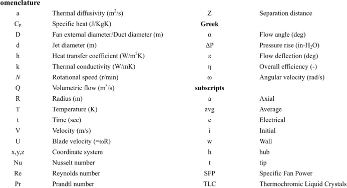
Nomenclature
a Thermal diffusivity (m2/s) Z Separation distance
CP Specific heat (J/KgK) Greek
D Fan external diameter/Duct diameter (m) α Flow angle (deg)
d Jet diameter (m) ΔP Pressure rise (in-H2O)
h Heat transfer coefficient (W/m2K) ε Flow deflection (deg)
k Thermal conductivity (W/mK) η Overall efficiency (-)
N Rotational speed (r/min) ω Angular velocity (rad/s)
Q Volumetric flow (m3/s) subscripts
R Radius (m) a Axial
T Temperature (K) avg Average
t Time (sec) e Electrical
V Velocity (m/s) i Initial
U Blade velocity (=ωR) w Wall
x,y,z Coordinate system h hub
Nu Nusselt number t tip
Re Reynolds number SFP Specific Fan Power
Pr Prandtl number TLC Thermochromic Liquid Crystals
small fans or impingement jets, still remains an attractive cooling mechanism due to the inexpensiveness and the mechanical simplicity of the design. Additionally, forced air systems can provide heat transfer rates that are 10 times greater than those available with natural convection or radiation.
Small axial fans can be assumed as impingement jets with a relatively big stagnation point region. Impinge-ment cooling, through single or multiple jets (fans) [8-11], finds great applicability in cooling of electronics due to the very high heat and mass transfer rate while the con-tinuously injected coolant flow ensures very high heat fluxes in the stagnation region of the jet. However, the continuous demand for higher temperatures within the electronic boxes requires new cooling concepts and more advanced cooling techniques to be considered. The over-all operational performance of smover-all axial cooling fans in terms of pressure drop and heat transfer removal capa-bilities can be affected by many parameters. For example, blade metal angles [12] and tip leakages [13] can be a critical factor in determining how well a cooling fan will perform since the position of the fan blades within the axial flow fan housings affects the flow conditions. A new concept for further improvement of the performance and efficiency curves includes contra rotating fan impel-lers [14] however the increase in noise has to be considered [15]. Many other factors such as blade num-ber, external diameter, hub/tip ratio etc. can affect the overall performance and the cooling efficiency of small axial fans. However, very little information of the effect of stators has been reported in the open literature.
This investigation examines experimentally the effect
of stators on the performance and the heat transfer capa-bilities of small axial cooling fans. A single fan impeller, followed by nine stator blades in the case of a complete stage, was used for all the examined configurations. The constant speed stage performance method and the tran-sient liquid crystal technique were used for the perform-ance and the heat transfer experiments, respectively. The results are analyzed by various post-processing proce-dures aiming to clarify and quantify the effect of stators on the operability of the cooling fans at low separation distances (Z/D=0.2, 0.5 and 1) and normal rotational speeds (3000-6000r/min).
Fig. 1 Constant speed stage performance test rig Experimental Arrangement
Performance Measurements
Fan impeller and fan stage performance experiments were carried out in the constant speed stage performance test rig of Aristotle University of Thessaloniki (AUTH), shown in Fig.1. The setup consists of long upstream and downstream ducts of constant area, the test section where the fans were mounted and a throttle valve at the exit plane. Air movement inside the pipe was induced by the
fan impeller mounted in the middle of the test section and powered by an adjustable DC-Power Supply. The blade row of the fan impeller consists of seven rotor blades. The performance measurements of the fan impeller and fan stage performed with the same motor and rotor blades, followed by nine stator blades of the same hub to tip ratio (Rhub/Rtip=0.4) in the case of a complete fan stage.
At a given rotational speed fan speed lines can be measured by varying the mass flow rate using a conical throttle valve at the exit plane of the test rig. The reduc-tion of the exit plane area reduces the mass-flow rate increasing the pressure difference at a given rotational speed, until the surge point is reached. At this position the diffusing blade passage is no longer able to handle the positive pressure gradient and hence flow separation occurs. The pressure rise of the fan at each throttle point is measured directly upstream (1) and downstream (2) of the fan configuration, at four equally spaced radial pres-sure tapping holes.
Fan rotational speed was measured using an infrared laser tachometer (DT2234A) between 3000r/min and 6000r/min (±2r/min). A programmable stepper motor controller (±0.01mm) was used for the movement of the throttle while mass-flow was evaluated with a Pitot - static tube placed in the centerline of the duct. The aver-age axial velocity (∼0.75V∞) was estimated with a probe traversing. Pressure signals were acquired using a cali-brated high performance multi-channel pressure acquisi-tion module (NetScanner 9016, ±0.05% after re-zeroing) via LabVIEW. Totally, twelve sets of measurement data were collected for each speed line in order to derive the performance maps of the fan impeller (rotor) and fan stage (rotor and stator).
Heat Transfer Measurements
The heat transfer experiments were carried out in the low speed wind tunnel of GTT at EPFL. The test facility, shown in Fig.2,consists of an axial blower used as an air source, long upstream rectangle ducts, a heater mesh used for the temperature step in the flow, the fan impel-ler/stage placed at the exit of the tunnel and the target plate placed at three different separation distances of
Z/D=0.2,0.5 and 1.0.
Fig.2 General layout of the low speed wind tunnel
The heat transfer experiments were carried out using the transient liquid crystal technique [16-18]. This tech-nique uses the full surface temperature history derived from the colour of the liquid crystals in order to obtain full surface heat transfer coefficient distributions on the target plate. The main advantages are the high resolution obtained and the minimum intrusiveness of the flow. TLC are sprayed on the surface of the target plate using an air brush while black paint is applied above liquid crystals in order to create a black background providing brilliant colors. A narrow bandwidth type (31.5oC –
32.8oC) of TLCs was used for all experiments while the
green color was used for the post-processing. Liquid crystals were calibrated with a surface thermocouple glued in the middle of the target plate.
In a typical transient heat transfer experiment, the flow temperature is subjected to a sudden temperature step and the optical response of the liquid crystal surface coating is monitored using a digital video camera at the back of the target plate. If the thermal conductivity of the model is sufficiently low, the wall temperature response is lim-ited to a thin layer near the wall surface while the lateral conduction is assumed relatively small and hence negli-gible. Therefore, the heat conduction into the model can be assumed to be one-dimensional when a semi-infinite medium approach is used. Numerical and analytical techniques can be used to solve the 1D transient conduc-tion equaconduc-tions. The relaconduc-tion between the wall surface temperature, Tw, and the heat transfer coefficient, h for
the semi-infinite case is then described by:
2 1 w i g i T T e erfc T T ; w w w t h C k (1)where, ρw, Cpw and kw are the Perspex density, specific heat and thermal conductivity, Ti and Tg are the initial
wall and gas temperatures and t is the time from the ini-tiation of the heating step. Gas temperature corresponds to the jet total temperature and is measured in the plenum. The temperature step in the flow achieved with a heater mesh [19], which has the capability of providing an al-most instantaneous temperature step in the mainstream flow through the Joule Heating law. Three layers of me-tallic heater meshes, with open area of 25%, were used for the initiation of the heating step. Power to the mesh is supplied through a 5kW DC-Power supply. The response time of the device needed to reach steady state condition has been measured to less than 60msec and hence assumed suitable for the creation of the temperature step in the flow. The temperature of the flow upstream of the fan was ac-quired via LabVIEW at a sampling rate of 25Hz.
A single jet configuration placed at the same position with the fans providing similar illumination and viewing angle settings was used for the validation of the meas-urement technique. The results of the standard single
impingement case of Z/d=2 and Red=23000 were com-pared with literature data indicating good agreement over a certain radial distance, as shown in Fig.3.
Fig. 3 Validation of the measurement technique Results and Discussion
Performance data
Fan selection for a particular application is usually concerned with its characteristic curve which defines a relation between pressure and mass-flow. For axial fans and incompressible flows, due to the low developed pressure rise, the characteristic curve for standard at-mospheric conditions can be expressed as a relation be-tween the achievable static pressure difference and the mass flow rare at a given rotational speed. The main ad-vantages of axial flow fans are their high efficiency, compactness and simplicity of installation. However, in all applications, fan selection involves choosing the most inexpensive combination of size, arrangement and type while providing stable operation.
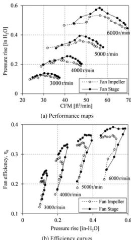
Fig. 4 indicates the overall performance of the fan impeller and the fan stage configuration. Fig.4 (a) indi-cates the performance map of the two studied cases where on both situations the inclination of the curves in the unstalled part is constant as the rotational speed in-creases indicating the incompressible character of the flow. However, the slope of the speed lines is greater when guide vanes are installed after the fan rotor. This is due to the direct straightening of the flow and the pres-sure recovery achieved within the stators’ passages. As a result, higher static pressure rise can be obtained for a given mass flow rate at given rotational speed. Increased values of static pressure are desirable when the geometry of the cooling object is relatively complex which result in a higher pressure drop through the cooling system. Al-though complex shapes, containing obstacles and rough-ened surfaces create turbulent flow conditions, and thus more heat to be removed is permitted, additional power is required in order to overcome the added flow resistance. However, the increase in static pressure is relatively low resulting in a reaction stage efficiency (static pressure rise achieved by the rotor divided by the static pressure
rise achieved by the stator) of approximately 90%. Addi-tionally, the experimental data indicate that the installa-tion of stators after the rotor maintains the operainstalla-tional mass flow range at a given speed line unaffected.
(a) Performance maps
(b) Efficiency curves
Fig.4 (a) Performance maps and (b) efficiency curves for the fan impeller and the fan stage configuration
Fig. 4 (b) indicates the overall efficiencies for the two studied cases. Fan efficiency is defined as the ratio of the power transferred to the airflow to the power used by the fan, and can be expressed as:
out st e in P P Q P VI (2) where ΔP is the static pressure rise, Q is the volumetric flow and P is the input and output power. In general, fan efficiency increases with rotational speed since the in-crease in static pressure and volume flow is higher than the increase in electrical consumption. Furthermore the best operation point in terms of maximum efficiency is different than the point of maximum power output since the peak in the efficiency curve is observed, as expected, before the surge point is reached. The efficiencies of the fan stage are higher compared with the fan impeller in the unstalled part of the characteristic curve due to the higher static pressure rise achieved through the fan stage at a given mass flow rate and hence electrical input
(rota-tional speed). However, further decrease of mass flow (increase of pressure rise) results in stall of the rotor blade passage and a sharp reduction of the achievable pressure rise which degrades sharply fan efficiency. The differences in the efficiency curves are negligible in the stalled region between the fan impeller and the fan stage. The general trends and the slope of the curves are the same over the entire range of rotational speeds involved in this study indicating that no compressibility effects appeared.
Fig. 5 Specific fan power for the fan impeller and the fan stage configuration
An alternative way of describing the energy efficiency is the Specific Fan Power (SFP) measured in Ws/m3.
SFP can be expressed in units of pressure, since pressure is a measure of energy per m³ air. The relation between SFP, fan pressure rise, and fan efficiency is simply:
SFP st e P (3) where ηe is the overall efficiency of the fan and ΔP is the total static pressure difference through the fan. Fig. 5 illustrates SFP for the fan impeller and fan stage as a function of mass flow rate at various speed lines. Con-trary to overall efficiency curves (Fig.4a) there is no
‘peak’ or a ‘best’ operating point. At a given speed line,
SFP is continuously reduced with increasing mass flow. Additionally, as expected, there is no difference between the SFP values of the fan impeller and the fan stage. This is because SFP is a measure of the electric power that is needed to drive a fan relative to the amount of air that is circulated through the fan. Given that rotational speed depends only on the electrical input and stators do not affect the operation range of the fan (Fig.5), installation of guide vanes after the rotor maintain the specific power of the fan system constant.
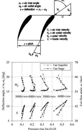
Fig.6 indicates the deflection angle (ε) and the exit flow angle (α2) of the rotor blade for the two studied cases. The velocity triangles on the rotor blade of the fan
stage have been calculated at the mid-span of the blade (50% span) assuming a reaction stage efficiency of 90% as well as negligible radial equilibrium effect which means constant static pressure distribution along the blade span. A schematic of velocity triangles at the inlet and outlet of the rotor blade is presented in upper part of the figure. As the throttle valve (see Fig.1) reduces the exit flow area of the test rig and hence pressure rise is gradually increased, the exit flow angle (α2) remains con-stant for the two studied cases, at approximately 55deg and is independent of the rotational speed. The reduced mass flow (Vα in the upper figure) increases also the inlet flow angle (α1) which in combination with the constant
α2, result in a sharp increase of the deflection of the flow (ε=α2-α1) in the unstalled part of the characteristic curve. The deflection angle reaches a maximum when the surge point is reached and therefore flow separation occurs. The separated flow blockages the blade exit area and destructs the diffusive character of the blade passage. Subsequently, further decrease of mass-flow steeply in-creases the exit flow angle (α2) and therefore abrupt re-duction of the deflection angle (ε) is observed. Addition-ally, the deflection angle is slightly increased with the rotational speed while the smaller inclination of the curve at higher speed lines is a direct consequence of the broader operational range.
Fig. 6 Velocity triangles notation and flow angles for the rotor blade of the two studied cases
Fig.6 indicates also that the flow angles, and hence the velocity triangles, are similar for the rotor of the fan im-peller and the fan stage. This indicates that the behavior of the flow on the rotor blade is independent of any downstream guide vane installation. The contribution of stator is then limited on the transformation of the swirl velocity induced by the rotor into static pressure, due to the pressure recovery within their passages.
Heat Transfer Data Surface contours
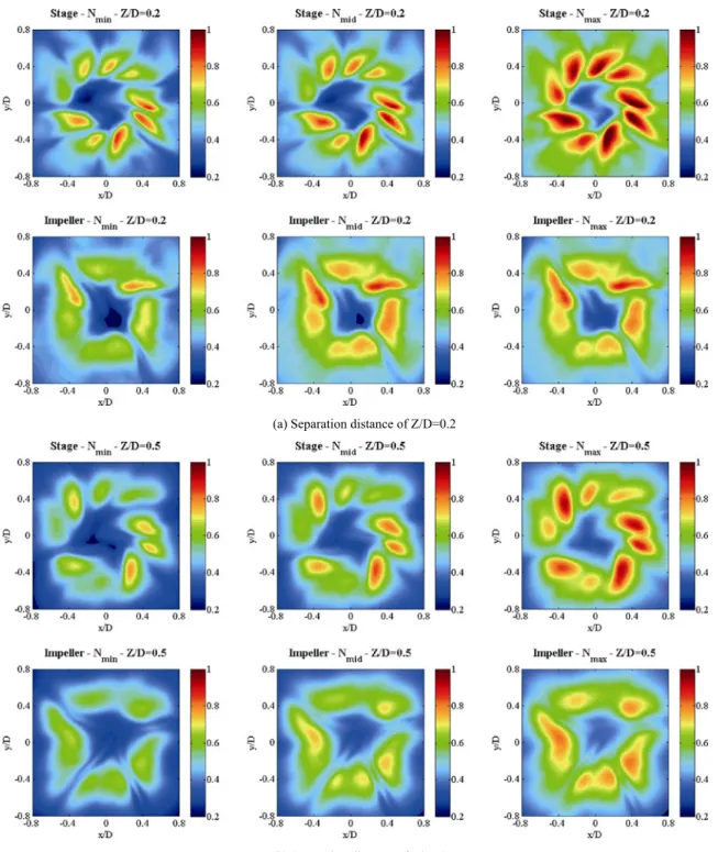
Fig.7 indicates surface contours of the heat transfer coefficient on the target plate normalized with the maxi-mum value appeared on these data, approximately 300 W/m2K on the stage configuration at Z/D=0.2 and
maximum rotational speed. For both cases heat transfer is
(a) Separation distance of Z/D=0.2
(b) Separation distance of Z/D=0.5
enhanced with increasing rotational speed in agreement with the basics of the heat transfer theory. However, heat transfer distribution is highly affected by the exit flow angles from the fan blades and the diversion of the flow around the motor supports at the fan outlet. In the case of a complete fan stage and Z/D=0.2, stators restore the air flow in axial direction and normal to the target plate. As a result, peak values of heat transfer rate appear as traces of the guide vanes due to the increased velocities at the wake of the stator blades. On the other hand, the distribu-tion of the heat transfer coefficient of a single fan impel-ler is more uniform and the discontinuations appeared are due to the supports of the fan motor similar to [20]. All the surface contours indicate a central region (dark blue color) where the low values of heat transfer coefficient is a direct consequence of the fan hub since the net exit area of the flow is actually a ring where Rh/Rt=0.4.
Similar results are observed at Z/D=0.5, however, the overall heat transfer coefficient is considerably lower indicating a degradation of heat transfer rate as the sepa-ration distance increases. Additionally, the ring of the high heat transfer rate (green and red color) appears closer to the edges of the target plate indicating a spread-ing of the flow at higher Z/D. Note also that the heat transfer in the central ‘’uncooled’’ area (fan hub) is en-hanced in the case of a single fan impeller. This is proba-bly, due to the absence of stator blades where the re-maining swirl of the flow induced by the rotor forces the jet ring produced by the fan to move in the radial direc-tion and hence in the fan hub region.
Local heat transfer rate
Fig.8 indicates the local heat transfer distribution in terms of Nusselt number, in the angular direction (R/D=0.1 and 0.35) at 6000r/min and the three separation distances. At Z/D=0.2 and R/D=0.35 the peaks of the heat transfer coefficient at the wake of the stator blades are clearly seen as stator blade wake traces while the distri-bution of the heat transfer in the case of the fan impeller is slightly more uniform providing smaller fluctuations. Closer to the center of the impingement region (R/D=0.1) the Nu number distribution for the two cases lies at the same level is more uniform due to the smaller impact of the wake of the blades. At Z/D=0.5, similar results are obtained, however, close to the stagnation region (R/D=0.1) the achievable heat transfer rate is slightly higher in the case of a single fan impeller. The difference between the two cases is more evident at Z/D=1 where the heat transfer range of the fan impeller is considerably higher than the case of the fan stage not only in the stag-nation region but also at a greater radial distance (R/D=0.35). Similar trends observed by a few studies focused swirling impinging jets [21-23]. They reported enhanced heat transfer rates in the stagnation region at
low swirl numbers and Z/D between 1 and 2. Swirl ve-locity enhances the spreading of the jet and the mixing with the surroundings resulting in higher turbulence val-ues and thus higher heat transfer coefficient. However, at very low Z/D (0.20.5) there is no space for the devel-opment of the jet potential core and as a consequence the heat transfer rate is mainly affected by the amount of mass-flow which is the same in the case of the fan im-peller and the fan stage configuration.
Fig. 8 Angular Nu number distribution at 6000r/min and Z/D=0.2, 0.5 and 1.
Average heat transfer rate
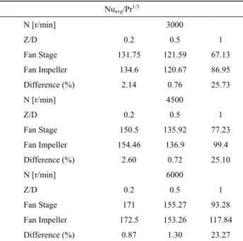
The area averaged Nu number ratio on the target plate is indicated in Fig. 9 as a function of the separation dis-tance (Z/D) and the rotational speed (N). In the first part
of the figure is observed a decrease of the average heat transfer rate as the separation distance increases from 0.2 to 1 fan diameters. Note that the average heat transfer rate achieved by the fan impeller and fan stage is fairly the same over the entire range of speed lines at low sepa-ration distances (Z/D=0.2 and 0.5) since there is no space for the development of the jet and the heat transfer rate is mainly affected by the amount of mass-flow, which is the same for the two cases. In particular, at Z/D=0.2 and
Z/D=0.5 the maximum difference between the Nu
num-ber ratio of the fan impeller and the fan stage configura-tion is 2.6% and 1.3%, respectively as shown in Table 1. However, further increase of separation distance (Z/D=1) allows a small development of the fan jet and therefore the average heat transfer is also affected by the flow con-ditions at the fan outlet. Absence of stators, in the case of a fan impeller, result in swirling flow conditions and en-hanced cooling capabilities for the entire range of rota-tional speeds. The average heat transfer rate achieved by the fan impeller at Z/D=1 is approximately 25% higher compared to the complete fan stage; percentage which is fairly enough in order to have a positive impact on the operation of an electronic device. Similar results on the averaged heat transfer obtained by [23].
Experimental Uncertainties
An uncertainty analysis performed on the heat transfer experimental results of this study in order to provide in-
Fig. 9 Area averaged Nu number ratio as a function of Z/D and rotational speed (rpm)
Table 1 Area averaged Nu number ratio on the target plate Nuavg/Pr1/3 N [r/min] 3000 Z/D 0.2 0.5 1 Fan Stage 131.75 121.59 67.13 Fan Impeller 134.6 120.67 86.95 Difference (%) 2.14 0.76 25.73 N [r/min] 4500 Z/D 0.2 0.5 1 Fan Stage 150.5 135.92 77.23 Fan Impeller 154.46 136.9 99.4 Difference (%) 2.60 0.72 25.10 N [r/min] 6000 Z/D 0.2 0.5 1 Fan Stage 171 155.27 93.28 Fan Impeller 172.5 153.26 117.84 Difference (%) 0.87 1.30 23.27
formation for the effect of measurement errors and their propagation on the calculation of the heat transfer coeffi-cient. The estimation of the uncertainties associated within the current investigation is based on the method of small perturbations [24], which has been successfully applied in heat transfer measurements obtained with a transient liquid crystal technique [25-26].
The effect of each type of measurement error on the area averaged heat transfer rate is considered in isolation. The error analysis was performed by applying small per-turbations in the test case of a fan stage at Z/D=0.2 and
N=4500r/min. The results are shown in Table 2 where the
maximum error in the calculation of heat transfer coeffi-cient is approximately 11%.
Table 2 Uncertainty analysis of the experimental results Values Error Error in havg [%]
Tj [oC] 43 ±0.25 1.89
Ti [oC] 20 ±0.15 1.13
TTLC [oC] 31.5 ±0.3 2.63
a (x10-7) [m2/s] 1.08 ±0.022 3.58
t [s] 10 ±0.05 1.85
Maximum error in havg 11.1
Summary and Conclusions
In the present work, the effect of stators on the per-formance curves and the heat transfer capabilities of a small axial fan impeller, followed by nine stator blades of the same hub to tip ratio in the case of a complete fan stage, were experimentally investigated. The constant
speed stage performance method and the transient liquid crystal technique were used for the performance and the heat transfer experiments, respectively. An error propaga-tion analysis indicated that the maximum error in the calculation of the area averaged heat transfer coefficient is approximately 11.1% which is a fairly good value for a transient heat transfer experiment.
The results indicated that fan efficiency and heat transfer distributions are affected by the flow conditions at the fan outlet. The findings of this investigation can be summarized as follows
:
Stator installation results in higher efficiency (in the order of 10%) and hence more economical operation at a given massflow rate and rotational speed.
The operation range, the specific fan power and the velocity triangles at the rotor blades are not affected by any stator installation and remain the same for the two studied cases.
In general, the heat transfer removal capabilities of a small axial fan impeller/stage are increased by reducing the separation distance (Z/D) between the fan and the cooling object and increasing the rotational speed.
At low separation distances (Z/D=0.20.5) the local heat transfer distribution is highly affected by the condi-tions at the fan outlet. Peak values of heat transfer appear as traces of the stator blades in the case of a complete stage while the distribution is more uniform when only a fan impeller is used.
At low Z/D no detrimental differences were found in the area averaged heat transfer coefficient between the two studied cases. However, at Z/D=1, increased heat transfer rate of approximately 25% is observed in the case of a fan impeller which is assumed enough to affect the operability of an electronic device.
Acknowledgements
The authors acknowledge Georgios Michailidis from École Polytechnique (Paris, France) for his contribution during the post processing of experimental data as well as Prof. Jens von Wolfersdorf and Prof. Bernhard Wei-gand from ITLR of Stuttgart University (Germany) for their overall support during the design of the heat transfer test rig.
References
[1] Mohamend, M. M. (2006). Air Cooling Characteristics of a Uniform Square Modules Array for Electronic Device Heat Sink,. Applied Thermal Engineering, 26, 486–493. [2] Chomdee, S., & Kiatsiriroat, T. (2006). Enhancement of
Air Cooling in Staggered Array of Electronic Modules by Integrating Delta Winglet Vortex Generators.
Interna-tional Communications in Heat and Mass Transfer, 618626.
[3] Jiang, J. Z., & Lin, S. (2001). Similarity of Heat Transfer on Heat Source Elements in the Entrance Region in Elec-tronic Equipment. Journal of Thermal Science, 10(2), 164169.
[4] Roy, G., Palm, S., & Nguyen, C. (2005). Heat Transfer and Fluid Flow of Nanofluids in Laminar Radial Flow Cooling. Journal of Thermal Science, 14(4), 362367. [5] Icoz, T., & Jaluria, Y. (2004). Design of Cooling Systems
for Electronic Equipment Using Both Experimental and Numerica Inputs. Journal of Electronic Packaging, 126, 465471.
[6] Sathe, S., & Samakia, B. (1998). A Review of Recent Developments in Some Practical Aspects of Air-Cooled Electronic Packages. Journal of Heat Transfer, 120, 830839.
[7] Garimella, S. V. (2006). Advances in Micro-Scale Ther-mal Management Technologies for Microelectronics. Mi-croelectronics Journal, 37, 1165–1185.
[8] Holloworth, R., & Durbin, S. (1992). Impingement Cool-ing of Electronics. Journal of Heat Transfer, 114, 607613.
[9] Brizzi, E., Bernhard, A., Bousgarbies, J., Dorignac, E., & Vullierme, J. (2000). Study of Several Impinging Jets. Journal of Thermal Science, 9(3), 217223.
[10] Quan, D., Liu, S., Li, J., & Liu, G. (2005). Cooling Per-formance of an Impingement Cooling Device Combined with Pins. Journal of Thermal Science, 14(1), 5661. [11] Weigand, B., & Spring, S. (2009). Multiple Jet
Impinge-ments - A Review. Int. Symp. on Heat Transfer in Gas Turbine Systems. Antalya, Turkey.
[12] Wang, L., Jin, Y., Cui, B., Jin, Y., Lin, J., Wang, Y., et al. (2010). Factors Affecting Small Axial Cooling Fan Per-formance. Journal of Thermal Science, 19(2), 126131. [13] Shiomi, N., Jin, Y., Kaneko, K., Kinoue, Y., & Setoguchi,
T. (2008). Flow Fields with Tip Leakage Vortex in a Small Axial Cooling Fan. Journal of Thermal Science, 17(2), 156162.
[14] Shigemitsu, T., Fukutomi, J., & Okabe, Y. (2010). Per-formance and Flow Condition of Small-Sized Axial Fan and Adoption of Contra-rotating Rotors. Journal of Ther-mal Science, 19(1), 16.
[15] Hidaka, R., Kanemoto, T., & Sunada, T. (2008). Per-formance and Accoustic Noise of Micro Multi-blade Fan. Journal of Thermal Science, 17(4), 343348.
[16] Baughn, J. W. (1995). Liquid Crystal Methods for Study-ing Turbulent Heat Transfer. International Journal of Heat and Fluid Flow, 16, 365375.
[17] Ireland, P. T., & Jones, T. V. (2000). Liquid Crystals Measurements of Heat Transfer and Surface Shear Stress.
Measurement Science and Technology, 11, 969986. [18] Stasiek, J. A., & Kowalewski, T. A. (2002).
Thermo-chromic Liquid Crystals Applied for Heat Transfer Re-search. Opto-Electronics Review, 10(1), 110.
[19] Gillespie, D., Ireland, P., & Wang, Z. (1996). Heating Element. British Patent Application, PCT/GB96/02017. [20] Stafford, J., Walsh, E., & Egan, V. (2009). Characterizing
Convective Heat Transfer Using Infrared Thermography and the Heated-Thin-Foil Technique. Measurement Science and Technology, http://iopscience.iop.org./0957- 0233/20/10/105401(11pp)
[21] Ichimiya, K., & Tsukamoto, K. (2010). Heat Transfer Characteristics of a Swirling Laminar Impinging Jet. Journal of Heat Transfer, 132, 012201/1-5.
[22] Uddin, N., Neumann, S. O., Lammers, P., & Weigand, B. (2008). Thermal and Flow Field Analysis of Turbulent Swirling Jet Impingement Using LES. High Performance
Computing in Science and Engineering, Springer, Hei-delberg, Part 5, 301315.
[23] Lee, D. H., Won, S., Kim, Y., & Chung, Y. (2002). Tur-bulent Heat Transfer from a Flat Surface to a Swirling Round Impinging Jet. International Journal of Heat and Mass Transfer, 45, 223227
[24] Moffat, R. J. (1988). Describing the Uncertainties in Ex-perimental Results. ExEx-perimental Thermal and Fluid Sci-ence, 1, 317.
[25] Chambers, A. C., Gillespie, D., Ireland, P. T., & Dailey, G. M. (2005). The Effect of Initial Cross Flow on the Cool-ing Performance of a Narrow ImpCool-ingement Channel. Journal of Heat Transfer, 127, 358365.
[26] Terzis A., Wagner, G and Ott P. (2012) Hole Staggering Effect on the Cooling Performance of Narrow Impinge-ment Passages, ASME Turbo Expo 2012/GT68323, Glasgow, Scotland.