HAL Id: inria-00443634
https://hal.inria.fr/inria-00443634
Submitted on 31 Dec 2009
HAL is a multi-disciplinary open access
archive for the deposit and dissemination of
sci-entific research documents, whether they are
pub-lished or not. The documents may come from
teaching and research institutions in France or
L’archive ouverte pluridisciplinaire HAL, est
destinée au dépôt et à la diffusion de documents
scientifiques de niveau recherche, publiés ou non,
émanant des établissements d’enseignement et de
recherche français ou étrangers, des laboratoires
Real-time Rendering of Heterogeneous Translucent
Objects with Arbitrary Shapes
Yajun Wang, Jiaping Wang, Nicolas Holzschuch, Kartic Subr, Jun-Hai Yong,
Baining Guo
To cite this version:
Yajun Wang, Jiaping Wang, Nicolas Holzschuch, Kartic Subr, Jun-Hai Yong, et al.. Real-time
Render-ing of Heterogeneous Translucent Objects with Arbitrary Shapes. Computer Graphics Forum, Wiley,
2010, 29 (2), pp.497-506. �10.1111/j.1467-8659.2009.01619.x�. �inria-00443634�
EUROGRAPHICS 2010 / T. Akenine-Möller and M. Zwicker (Guest Editors)
Volume 29 (2010), Number 2
Real-time Rendering of Heterogeneous Translucent Objects
with Arbitrary Shapes
Yajun Wang†‡§¶ Jiaping Wang† Nicolas Holzschuch‡¶ Kartic Subr‡¶ Jun-Hai Yong§ Baining Guo†§
† Microsoft Research Asia § Tsinghua University
‡ INRIA Grenoble Rhône-Alpes ¶ CNRS and Université de Grenoble, Laboratoire Jean Kuntzman
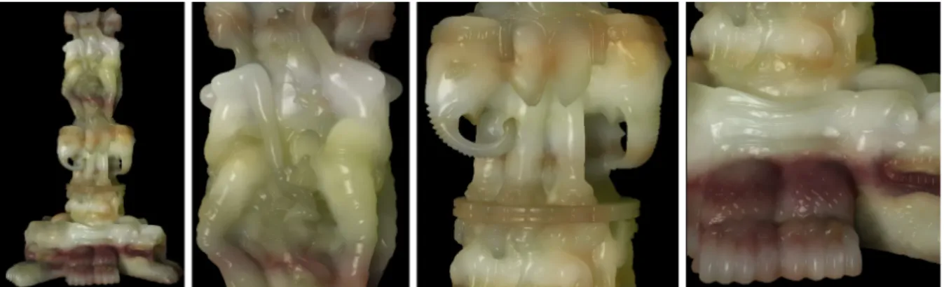
Figure 1:Rendering results at 22 frames per-second of the Stanford Thai Statue (157 K triangles) with our system.
Abstract
We present a real-time algorithm for rendering translucent objects of arbitrary shapes. We approximate the scatter-ing of light inside the objects usscatter-ing the diffusion equation, which we solve on-the-fly usscatter-ing the GPU. Our algorithm is general enough to handle arbitrary geometry, heterogeneous materials, deformable objects and modifications of lighting, all in real-time. In a pre-processing step, we discretize the object into a regular 4-connected structure (QuadGraph). Due to its regular connectivity, this structure is easily packed into a texture and stored on the GPU. At runtime, we use the QuadGraph stored on the GPU to solve the diffusion equation, in real-time, taking into ac-count the varying input conditions: Incoming light, object material and geometry. We handle deformable objects, provided the deformation does not change the topological structure of the objects.
1. Introduction
Subsurface scattering of light is a complex phenomenon that occurs in many materials such as jade, marble and human skin. It plays an important role in the realism of rendered scenes, but unfortunately is also challenging to simulate. In translucent objects, the outgoing radiance at each point on the surface depends on three factors: Incoming radiance at all points on the surface, the path followed by the light inside the object as well as the optical properties along this path.
Accurately rendering a translucent object can take sev-eral hours with off-line physical simulation. To accelerate the rendering process, Jensen et al. [JMLH01,JB02] intro-duced the diffusion approximation: Assuming homogeneous materials and infinite planar boundaries, multiple scattering effects can be simulated efficiently using a dipole
approxi-mation. However, the constraints for this diffusion approx-imation are not fully satisfied by many real-world objects, that have complex shapes and are composed of heteroge-neous scattering materials.
The diffusion equation [Ish78] fully describes subsurface multiple-scattering effects in translucent objects, including heterogeneous materials. In practice, solving the diffusion requires a discretized model of the interior of the translucent object. Wang et al. [WZT∗08] used a regular grid, the
poly-grid; this grid had to be built manually, and is not suited for
complex geometry (high genus or thin features).
In this paper, we present the first method to solve the dif-fusion equation, in real-time, on objects of arbitrary shapes with heterogeneous materials. Our method is based on a 4-connected structure, the QuadGraph. In a pre-processing
step, we build the QuadGraph automatically as the connec-tivity graph of a tetrahedralization of the object. At each node, we store the diffusion coefficients of the material. This QuadGraph is then stored on the GPU in a compact way, exploiting the regular connectivity. At run-time, we use the GPU to solve the diffusion equation at each node of the QuadGraph, in real-time, accounting for dynamic material properties and deformations to the geometry. Our algorithm is robust enough to handle objects with arbitrary genus and arbitrarily thin features (see figures 1 and10).
We first review the literature on translucent materials and subsurface scattering (section2). Next, we present the back-ground on the diffusion equation (section3). In section4we describe our datastructure, the QuadGraph, its construction and the linearization of the diffusion equation. Practical im-plementation details including compact storage of the Quad-Graph on the GPU, solving the equation and rendering are explained in section5. In section6, we present experimental results and timings. Finally, in section7, we propose direc-tions for future work.
2. Related Work
Translucent Materials: Subsurface scattering
ef-fects can be simulated using Monte-Carlo
meth-ods [DEJ∗99,PH00,LPT05] or Photon Mapping [JC98]. These methods are physically accurate, and apply to any object or material, but require considerable rendering time for each frame (usually hours). Jensen et al. [JMLH01] introduced the diffusion approximation for homogeneous materials with an infinite planar boundary. With this approximation, the rendering time is lowered to minutes. Dachsbacher and Stamminger [DS03] extended this work to achieve real-time rendering, using the same approximation. Several papers have extended this work to multi-layered translucent materials, e.g. [DJ05], and especially human skin [GHP∗08,DWd∗08]. Arbree et al. [AWB08] used the lightcuts approach [WFA∗05,WABG06] to render objects of arbitrary shape, with homogeneous materials. Several papers have presented algorithms for fast rendering of par-ticipating media [MSM∗04,ZRL∗08,SKLU∗09], but they are restricted to regular volumetric shape representation. Acquisition: A different line of research targets the acquisition of material properties, for translucent objects: Tong et al. [TWL∗05] for quasi-homogeneous translucent materials, Goesele et al. [GLL∗04] for acquiring the properties of an entire object, Peers et al. [PvBM∗06] for capturing the properties of a flat sample. These methods sample the complete light transport operator for the object or for a material sample. Consequently, they store very large data sets that restricts editability of material properties.
Precomputed Radiance Transfer: Recently
Precom-puted Radiance Transfer [SKS02] has been extended
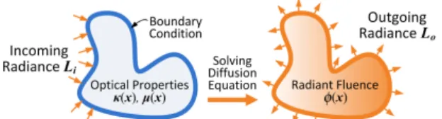
Figure 2: Rendering with diffusion equation. to render translucent objects in real-time, through pre-computation of the light transport due to subsurface scattering [HV04, WTL05]. Xu et al. [XGL∗07] and Wang et al. [WCPW∗08] precomputed the subsurface scattering of a series of 1D homogeneous basis scattering profiles and linearly combined them on-the-fly with varying weights to achieve runtime alteration of optical proper-ties. These methods require precomputation of the light transport, with fixed material properties and/or geometrical shape of the object. They are not suited for applications that require dynamic editing of the material or the geometry. Diffusion Equation: Multiple scattering effects can be modeled by the diffusion process [Ish78], described by a PDE– the diffusion equation– that can be numerically solved. The Diffusion Equation was first introduced in com-puter graphics [Sta95] for rendering participating media. Haber et al. [HMBV05] extended this work to objects of arbitrary shapes, using embedded boundary discretization. Wang et al. [WZT∗08] achieved real-time rendering of translucent objects on the GPU, using a quasi-regular 6-connected structure, the polygrid. However, this method is restricted to objects with simple geometry (low genus, no sharp features).
Our algorithm is also based on the diffusion equation, al-lowing us to handle heterogeneous materials. However, the main difference with previous work is that we discretize translucent objects using tetrahedra instead of cubic grids. This allows us to handle arbitrary geometry, in real-time.
3. The Diffusion Equation
Light entering a translucent object interacts with the material of the object and is scattered several times before leaving the object. If we focus only on this multiply-scattered compo-nent, light within the object is related to the light entering the object by a PDE, the diffusion equation [Ish78,Sta95] with incoming radiance being the boundary condition (see figure
2). The solution to the diffusion equation expresses the dis-tribution of light throughout the object and light leaving the object is obtained by computing the outgoing radiance at the surface.
More formally, consider an objectΩ with boundary∂Ω, composed of a highly scattering, non-emissive, heteroge-neous material, defined by its absorption coefficientµ(x) and reduced scattering coefficientσs′(x) [JMLH01]. The dif-fusion equation defines the radiant fluxϕ(x) within this
ob-1316 / Real-time Rendering of Heterogeneous Translucent Objects 3
Figure 3: QuadGraph (c) is constructed from the
tetrahe-dralization (b) of a surface mesh by taking centroid of tetra-hedra as nodes and faces as edges. (d) zooms in the blue box region of (c). Green line: a link between inner nodes. Red line: a link between inner node and surface node.
ject as:
∇ · (κ(x)∇ϕ(x)) − µ(x)ϕ(x) = 0, x ∈ Ω (1) whereκ(x) = [3µ(x) + σs′(x)]−1.
We use the diffusive source boundary condition as de-scribed by Arbree [AWB09] based on the Robin boundary condition [HST∗94,SAMD95], which relates the incoming radiance Lion the surface of the object∂Ω to the radiant flux as ϕ(x) + 2Aκ(x)∂ϕ(x)∂⃗n = 4 1− Fdr q(x), x∈∂Ω (2) where q(x) = ∫ 2π Li(x,ωi)(⃗n·ωi)Ft(ωi)dωi, (3)
A = (1 + Fdr)/(1− Fdr) and q(x) is the diffused incoming light at the surface point x. Ftand Fdrare the diffuse Fresnel transmittance and Fresnel reflectance coefficients, respec-tively [JMLH01]. Both are functions of the refraction index η.
Once radiant fluxϕ(x) inside the object is determined, we compute the outgoing radiance on the boundary Lo(xo,ωo) as its derivative along the normal ⃗n at point xo ∈∂Ω [AWB09]: Lo(xo,ωo) = Ft(ωo) 4π [( 1 +1 A ) ϕ(x) − 4 1 + Fdr q(x) ] (4)
4. Solving the Diffusion Equation on QuadGraph We represent the boundary condition and solve the diffusion equation in a discrete domain. A regular 4-connected volu-metric graph called QuadGraph is proposed to serve as such a domain, which is automatically constructed given the sur-face geometry of the object. In this section, we describe how to construct the QuadGraph and solve the diffusion equation on it.
4.1. QuadGraph
The QuadGraph is a volumetric graph; nodes are connected to either 1 other node (surface nodes), or to 4 other nodes
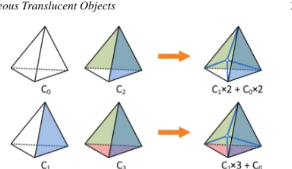
Figure 4: Four types of tetrahedron (C0−3) with 0-3
out-side face(s). Outout-side faces, rely on the volume boundary, are filled with solid color. C2/C3tetrahedra are split by adding
a new vertex and four edges shown in blue. Splitting a C2
tetrahedron results in two C0tetrahedra and two C1
tetrahe-dra. Splitting a C3tetrahedron results in one C0tetrahedra
and three C1tetrahedra.
(inner nodes). Surface nodes (N∂Ω) are positioned at the sur-face of the object, and they sample the incoming radiance and represent the boundary condition. Inner nodes (NΩ), dis-tributed inside the volume, sample volumetric optical prop-erties and represent the solution of the diffusion equation, radiant flux. The entire graph (NΩ+) is the union of surface
nodes and inner nodes, NΩ∪ N∂Ω.
As shown in figure3, to build the QuadGraph, we start with an automatic tetrahedralization of the triangle mesh [ACSYD05,LS07]. After the tetrahedralization, a given tetrahedron can have from 0 to 3 of its faces on the boundary of the object (we assume that there are no isolated tetrahe-dra).
We split all tetrahedra with 2 or 3 faces on the boundary by adding a new vertex at their centroids as shown in figure4, so that the resulting tetrahedral mesh only contains tetrahedra with 0 or 1 faces on the boundary.
We then build the QuadGraph as the connectivity graph of this tetrahedral mesh as illustrated in figure5: each tetra-hedron is converted into a graph node, located at its troid. If two tetrahedra share a given face, then their cen-troids are connected in the graph. Tetrahedra with one face on the boundary of the object are converted into a set of two connected nodes: an inner node and a surface node. The geo-metric position of the surface node is determined as the clos-est intersection between the surface mesh and the ray linking it to the inner node. Figure3shows an example of the Quad-Graph. Once we have built the initial QuadGraph, we refine
Figure 5: Construction QuadGraph from tetrahedron mesh.
Left: a C0tetrahedron is converted to an inner node (Green).
Right: a C1 tetrahedron is converted to an inner node
the position of the inner nodes for even distribution by ap-plying reaction-diffusion [Tur91] to the 3D points.
Our method is based on the tetrahedralization method of Alliez et al. [ACSYD05], which produces nearly equilat-eral tetrahedra of regular size. It takes a single parameter, K, which controls how much larger tetrahedra inside the object are, compared to those near the surface.
4.2. Discretized Diffusion Equation
Once we have built the QuadGraph {NΩ, N∂Ω}, we
dis-cretize the Diffusion Equation (Equations1and2) into lin-ear equations using a Finite Difference Method (FDM), as in [Sta95]: 4
∑
j=1 1 di j2κ(nj)ϕ(nj)− (wκ(ni) +µ(ni))ϕ(ni) = 0 (5) ϕ(ns) + 2Aκ(ns)ϕ(ns )−ϕ(nk) dsk = 4 1− Fdr q(ns) (6) ni∈ NΩ ns∈ N∂Ω The sum in Equation5is over the four nodes njconnected to the node ni. In Equation6, nk is the single inner node connected to the surface node ns. In equation5, we use w = ∑4j=11/di j2, and d∗∗denotes the distance between two nodes, or the length of the graph edge connecting them.
We sample optical properties (κ and µ) at the graph nodes. q(ns) is the diffused incoming light for each surface node. We approximate the coefficients of Laplacian operator with the inverse distance (α = −2) [Tau95]. Once we have solved the diffusion equation described in section4.3, we find the outgoing radiance Lo(ns,ωo) according to the radi-ant flux of the corresponding surface nodeϕ(ns):
Lo(ns,ωo) =
Ft(ωo) (ϕ(ns)− 2q(ns)) 2π(1 + Fdr)
, ns∈ N∂Ω (7) 4.3. Solving the linearized equation
We solve the linearized equations (5, 6) on the Quad-Graph using the relaxation scheme as in [Sta95,WZT∗08]: we start by initializing the value of the radiant flux at each node toϕ0(n) (e.g. zero), and iterate the following steps until reach a user defined number of iterations.
ϕt+1(ni) = ∑4 j=1κ(nj)ϕt(nj)/di j2 wκ(ni) +µ(ni) ni∈ NΩ (8) ϕt+1(ns) = 2Aκ(ns)ϕt(nk) + dsk4q(n1+Fdrs) 2Aκ(ns) + dsk ns∈ N∂Ω (9)
To speed-up the convergence, we use a multi-resolution scheme, similar to [WZT∗08]. We design multiple levels h of the QuadGraph,{NΩh, N∂Ωh }. Each level is built,
indepen-dently, as a tetrahedralization of a simpler version of the sur-face mesh, with the number of sursur-face points decreasing by a factor of four between two hierarchical levels. Note that
the finest level uses the exact full QuadGraph, so no approx-imation is introduced by using the multi-resolution scheme if convergence is fulfilled.
After we have these multi-resolution representations of the object, we start by solving at the coarsest level, h = 0, use this solution as the starting point for solving at the next level, and iterate. The coarse level generates a blurred solu-tion (figure14b) with correct overall distribution and serves as the initialization for the finer level. Specifically, initial ra-diant flux at the level h + 1 is sampled from the solution of b nearby nodes on level h, with interpolation weights propor-tional to the square of the inverse distance [She68]:
ϕ(nh+1 x ) = b
∑
y=1 wxyϕ ( nhy ) (10) wxy= w′xy ∑b y=1w′xy w′xy= nh+1x − nhy −2.We treat surface nodes and inner nodes independently in this hierarchical sampling process. We used b = 4 for surface nodes, and b = 8 for inner nodes, i.e. each surface node at a finer level is computed by interpolating the values from 4 surface nodes at the coarser level. The interpolation weights between the different levels of the QuadGraph (wxy) are pre-computed as part of the pre-processing step. They are inde-pendent of the optical properties of the material, and invari-ant to smooth shape deformation.
5. GPU Implementation and Rendering
Our algorithm solves the diffusion equation inside the translucent object at each frame, without precomputation of the light transport, thus allowing for dynamic illumina-tion, optical properties and shape deformations. We store the QuadGraph in textures on the GPU as a pre-processing step. At each frame, we first sample the incoming illumination us-ing shadow mappus-ing on the surface of the translucent object, then solve the Diffusion Equation on the GPU using it as a boundary condition.
5.1. Storage
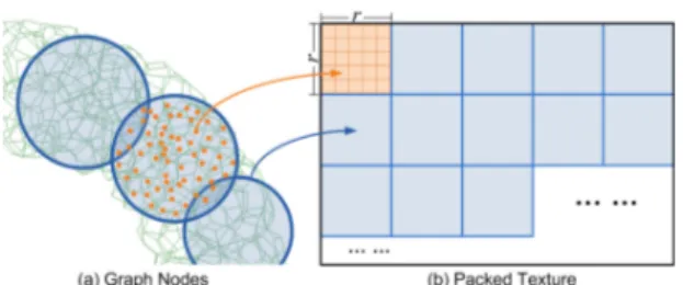
We store the QuadGraph itself on the GPU using 2D textures (see figure6). Each node of the QuadGraph corresponds to
Figure 6: Textures for encoding parameters. Upper row (a):
16-bits float textures that encode variables. Bottom row (b): 32-bits integer textures that encode constants.
1316 / Real-time Rendering of Heterogeneous Translucent Objects 5
Figure 7: Texture packing. Topologically nearby nodes (red)
are packed in the same texture block (blue).
a single index (u, v), applying to all the textures. The tex-tures are subdivided along one dimension (v) between sur-face nodes and inner nodes, so that the node type is easily determined by a simple test.
Connectivity is encoded using two 32-bits RGBA inte-ger textures, encoding for each node the indices of the con-nected nodes (two channels per index). We also use 2 RGBA textures of 16-bits floating-point numbers to encode the ge-ometric position of each node and its optical properties (κ(n), µ(n)). We uses 16-bits floating-point instead of 32-bits in any situation if the precision is sufficient, which re-duced the amount of video memory to be accessed.
A separate set of textures encodes the hierarchical lev-els of the QuadGraph: 32-bits RGBA integer textures to en-code the connectivity between the different levels, and 16-bits floating point numbers to encode the weights used for sampling results on the next hierarchical level. The entire GPU memory cost for our algorithm is roughly 20 MB for models with roughly 100 K vertices (see Table1).
A crucial point for a practical GPU implementation is im-proving the cache hit rate of graphics memory access on the GPU. We pack together nearby nodes (see figure7): the tex-ture is subdivided into multiple blocks of r× r texels, and each block is filled with a set of connected nodes. We use a greedy approach for filling the texture: starting from a seed node, we do a breadth-first traversal on the graph, and as-sign them to the block until we have reached r2nodes. The next node is then used as a new seed node, to fill the next block. When the traversal finds an already assigned node, it does not assign it to another block, but it still visits all the nodes that are connected to it. We iterate this process until all graph nodes have been assigned. In our experiments, we
bindtextureϕt+1to a FBO as the render target
rendera rectangle covering the texels containing the nodes to be updated, with fragment shader.
for eachfragment:
fetchindices of neighbouring nodes nj
fetchpositions and optical properties for ni, nj
compute Laplace weights based on distance between nodes compute value forϕt+1based on Eq.9or8.
end for
Figure 8: Pseudocode for a single iteration
use r = 32. Such a chosen is based on the tetrahedralization density of the geometry models used in our experiments.
For packing together inner nodes, we use the connectivity inside the graph. For surface nodes, we use proximity on the surface. In our experiments, this localized storage of the QuadGraph in textures results in a 30 % to 60 % speedup over random storage.
5.2. Solving the Equation
We solve the diffusion equation at each frame, recursively on each hierarchical level of the QuadGraph, starting with the coarsest level (h = 0) (see figure9for a pseudo-code of our algorithm).
For each level, we start by evaluating the incoming dif-fuse illumination on the surface, including shadows (using shadow mapping) and multiply with Fresnel transmission coefficient . Incoming light is stored in a 16-bits floating point texture, for each surface node of the QuadGraph.
We then solve the diffusion equation iteratively, using two auxiliary textures to store the radiant flux, before and after the current iteration (see figure8for the pseudo-code of a single iteration). After computing an iteration, we test for convergence. If we have converged at this hierarchical level, we move on to the next level, using the results at this level as a starting point, after re-sampling. Otherwise, we swap the two textures and compute the next iteration.
5.3. Displaying Results
We do not display the geometry of the original object; in-stead, we build a surfaceϒ that maps directly to the Quad-Graph, by triangulating all its surface nodes. Once we have computed the solution of the Diffusion Equation, we use it to compute the outgoing radiance Lofor all surface nodes ns using Eq.7, then we renderϒ.
6. Experimental Results
We have implemented our algorithm on an Intel Core2Duo 2.13GHz CPU, with 2GB memory and an NVIDIA Geforce 8800GTX GPU with 768MB graphics memory. We used GLSL to implement the algorithm on the GPU.
At each new frame:
for eachmulti-resolution level h
compute incoming light q(ns) on all surface nodes
initializeϕ(n) by sampling from level h− 1 whilenot converged
updateϕ(ns) for all surface nodes (Eq.9)
updateϕ(ni) for all inner nodes (Eq.8)
end while end for
compute radiance Lo(ns,ωs) for all surface nodes (Eq.7)
render the object surface using Lo
Scene Fig. QuadGraph Mem Prep Iter FPS Ns Ni K L (MB) (min) Thai 1 157k 369k 1 4 35 24 40 21.8 Gargoyle 10a 62k 139k 0.5 3 18 10 50 46.4 Topmod 10b 121k 260k 0.2 3 36 15 40 29.4 Buddha 10c 66k 120k 0.5 3 17 9 30 57.6 Fertility 10d 82k 182k 0.3 3 25 12 50 34.4 Twirl 10e 82k 226k 0.1 3 27 16 60 22.1 Heptoroid 10f 82k 178k 0.2 2 24 11 80 21.6 Lucy 10g 150k 363k 0.2 4 33 20 40 21.0
Table 1: Statistics of test scenes: Nsand Niare the number of
surface and inner nodes, respectively, of the QuadGraph at the finest level. L is number of multi-resolution levels; Mem is the total size of textures over all levels; Prep is the prepro-cessing time including tetrahedralization, QuadGraph con-struction and texture packing; Iter is the number of iterations of the solver at each level.
All images are rendered at 1024× 1024 with 2 × 2 super-sampling for antialiasing. We added surface shading to all results using the Cook-Torrance BRDF model [CT81]. We have tested our algorithm on several complex objects, with sharp geometric features (see figures 1 and10). Rendering statistics for all our models can be found in Table1.
6.1. Test Scenes
Figure 1 shows the rendering results of the Stanford Thai model with the colorful agate material. Our system generates the subsurface effects due to the highly heterogeneous ma-terial. Complex surface details and small geometry features, such as the trunk in the middle and claw in the bottom, are well preserved and exhibit rich visual effects with different lighting conditions. Please refer to the accompanying video for animated sequences.
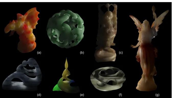
Figure10 shows rendering results with various objects. Objects with high genus (b, c, f), high curvature (b, e, f) and thin features (a, c, e, g) are well handled. We can also han-dle any kind of material and heterogeneities, such as wax (a, c, e, f), jade (b), and marble (d, g). Our algorithm produces convincing results in all cases, which demonstrates various visual effect on translucent materials, such as color bleed-ing (a, d, e, g), back-lightbleed-ing (b, c, d, f) and blurrbleed-ing of the geometry features (a, c, g).
6.2. Computation time
Figure12shows the computation time (in ms) for several test scenes, as a function of the number of tetrahedra. For three of our models, the Stanford Bunny, the double-hole donut (figure3) and the Fertility statue (figure10d), we have sev-eral tetrahedralization: they are plotted as lines. Other mod-els, for which we have a single tetrahedralization, appear as
0 50 100 150 0 250000 500000 750000 1e+06 R e n d e ri n g t ime (ms) Number of tetrahedra Bunny Double hole Donut Fertility Other models Lucy Thai statue Budha Gargoyle Heptoroid Twirl Topmod ball
Figure 12: Computation time, inms, as a function of the
number of tetrahedra. Models with several tetrahedraliza-tions are plotted as straight lines (Bunny, Donut, Fertility). Other models appear as points in the graph. For most of the models, the rendering time varies linearly with respect to the number of tetrahedra. The two outliers (Twirl and Hep-toroid) have thinner features and require more iterations.
points on the graph. For most of the models, the rendering time appears to vary linearly with respect to the number of tetrahedra. The two outliers are the Twirl (figure10e) and the Heptoroid (figure10f). These two models have thinner features, and require more iterations for convergence.
6.3. Comparison with Ground Truth
To study the effect of the parameter K on the results of our algorithm, we compared resulting images for different val-ues of K against a ground truth reference image that was computed using photon mapping. Figure11tabulates these results for four different values of K and shows difference images to the reference and scanline plots. A lower value for
K constrains the sizes of surface and internal tetrahedra to
vary less. While reducing K increases the number of tetra-hedra and hence computation time, it results in rendered im-ages that are closer to the ground truth. However, even the increased quality images render at interactive rates (8 fps). By increasing K, we can further increase the efficiency at the appropriate compromise of fidelity to the ground truth. The plots in the image show our result (blue) across two dif-ferent scanlines compared against the ground truth (black). For K = 0.1, the blue curve is quite close to the reference black curve.
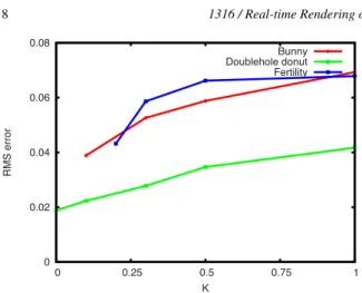
To obtain intuition about the “sweet spot”, or the value of K at which we achieve a suitable trade-off between qual-ity and efficiency, we plotted the relative root mean squared (RMS) error of our result (in comparison with the ground truth) against K for multiple models (see figure13). This plot reveals that even at K = 1.0 the RMS error is less than
1316 / Real-time Rendering of Heterogeneous Translucent Objects 7
Figure 10: We have tested our algorithm on several complex objects, including objects with high genus (b, c, f), high curvature
(b, e, f) and with sharp geometric features (a, c, e, g).
Ground Truth K = 1, N = 141k K = 0.5, N = 246k K = 0.3, N = 468k K = 0.1, N = 973k 21 ms 35 ms 68 ms 122 ms Image Dif ference y=300 y=400
Figure 11: Comparison between ground truth and our method, for different values of K [ACSYD05]. For this figure, we com-puted only the translucency effects, with no reflections on the surface, to ensure a fair comparison. First row: the actual pictures computed. Second row: pixel-by-pixel difference with reference image (top left). Third and fourth row: 1D plot of pixel values along a scanline. The positions of the two scanlines appear on the leftmost image of the second row. The values for the reference image are in black, our results are in blue. For K = 0.1, our results are quite close to the reference. Note that for all values of K, our algorithm finds the salient features of illumination, resulting in a good visual quality.
0 0.02 0.04 0.06 0.08 0 0.25 0.5 0.75 1 R MS e rro r K Bunny Doublehole donut Fertility
Figure 13: RMS error of the images computed with our
al-gorithm (compared to a reference image), as a function of K.
10 %. The plot also shows that we can achieve errors as low as 2 % at slight costs in efficiency.
Finally, we verified the contribution of the multi-resolution scheme to convergence rate by plotting relative errors against execution time, with and without the multi-resolution solver. Figure14 shows that the use of a multi-resolution solver significantly increases convergence rate.
6.4. Shape Deformation and Material Editing
Our system also supports runtime shape deformation as shown in figure15and the accompanying video. Any de-formation algorithm that is able to apply a dede-formation field to the object volume (e.g. [SP86,JSW05,LLCO08]), can be applied to drive the deformation of QuadGraph. Defor-mation described here is only changing on geometry shape, the material changing due to deformation (e.g. condensed by squeezing) is not considered. Runtime editing of the optical
Figure 14: The plot (a) compares relative error achieved
with (blue) and without (red) the multi-resolution solver. (b) the solution of the coarse level. (c) the solution of the finer level with (b) as initialization.
Figure 15: Our algorithm can handle deforming objects, as
long as the deformation does not break the underlying tetra-hedralization.
Figure 16: Our algorithm can handle changing the optical
properties at runtime.
properties is demonstrated in figure16(and accompanying video)
We can only handle deformations that maintain the under-lying tetrahedralization. Deformations are therefore limited in scope and amplitude: we cannot change the topology of the object.
Although we only show simple material optical editing operations, our system is flexible enough to work with com-plicated editing operations since the rendering takes the op-tical property volume as input directly.
6.5. Discussion
Real-time solver:The main advantage of our QuadGraph algorithm is its ability to solve the diffusion equation in real-time. Since there are no precomputations besides the tetrahe-dralization of the input geometry, our algorithm can handle dynamically changing the incoming lighting, material prop-erties, and even limited deformations of the geometry, with-out the need for precomputing the light transport.
1316 / Real-time Rendering of Heterogeneous Translucent Objects 9
Quality vs. efficiency: The parameter K can be used to trade-off accuracy for efficiency: large values of K result in a smaller number of inside tetrahedra, thus making the al-gorithm run faster, at the expense of accuracy. Small values of K give results that are more accurate, at the expense of rendering time. But even in its fast, low-quality version, our algorithm identifies the salient lighting features, resulting in a good visual quality, and it maintains RMS error under 10 % (see figure13).
Sampling: Just as any discretization scheme, our Quad-Graph domain requires adequate sampling for capturing high-frequency effects. That is, the tetrahedralization needs to be dense enough to capture variations in (1) incident il-lumination at the surface as well as (2) the optical proper-ties of heterogenous materials. The former is less of a prob-lem since multiple scattering results in a decimation of high-frequencies in the incident surface radiance. The latter prob-lem limits the range of editable materials that can be faith-fully rendered without re-tetrahedralization.
Arbitrary shape: The dipole approximation [JMLH01] breaks down at points with high curvature, while the poly-grid method [WZT∗08] is unable to handle thin features or geometries with high genuses. Since our discretization is based on the input geometry, our algorithm is robust to vari-ations in these features.
Discretization method: Our algorithm uses a Finite Dif-ference Method for discretizing the diffusion equation. Other algorithms have used a Finite Element Methods in-stead [AWB08,AWB09]. The latter is more accurate, but the former maps well to the GPU, allowing us to better take ad-vantage of the computing power of this architecture. 7. Conclusion and Future Work
In this paper, we introduced an algorithm for real-time ren-dering of translucent objects, of arbitrary shape, with hetero-geneous materials. Our algorithm is robust enough to handle objects with arbitrary genus and fine sharp features. Since all illumination computations are conducted in real-time, we can handle deformable objects as well as dynamic changes in the optical properties and lighting conditions. Our algo-rithm is based on a simple 4-connected graph, the Quad-Graph, built automatically from a tetrahedralization of the triangle mesh defining the surface of the object.
As most existing algorithms for approximating subsurface scattering, our algorithm is restricted to the multiple scatter-ing component of subsurface scatterscatter-ing. While this compo-nent is usually the most visible for optically dense materials, recent research [DLR∗09,WZHB09] have shown that low-order scattering effects can be quite impressive in some cir-cumstances. In future work, we will investigate computation of low-order scattering effects for increased realism.
Although our algorithm handles deformable objects, de-formations are limited, in the sense that the underlying
tetrahedralization must remain valid. We cannot change the topology of the object, or break it into pieces. Future work will include handling arbitrary deformations of the object.
Finally, we would like to extend our algorithm to de-couple the local scattering and handle it by texture space filtering as in [dLE07], for fine detailed material variation. Acknowledgements: We are grateful to Adam Arbree, Bruce Walter and Kavita Bala for sharing their latest work on the new diffusion equation formula and the helpful dis-cussions on its accuracy and robustness. We thank Shuang Zhao and Yue Dong for their source code, as reference, for the forward diffusion equation and photo-tracing. We also thank Jean-Claude Paul for the helpful discussions.
The authors from Tsinghua University were supported by the National Science Foundation of China (60625202, 60911130368) and Chinese 863 Program (2007AA040401). This work was funded in part by ANR (ANR-07-BLAN-0331 "HFIBMR"). Yajun Wang is supported by an INRIA internship grant.
Geometry model credits: Gargoyle, fertility and twirl in figure 10(a,d,e) are downloaded from the AIM@SHAPE Shape Repository (http://shapes.aim-at-shape.net/). Thai Statue, Buddha and Lucy in figure 1 and figure10(c,g) are downloaded from the Stanford 3D Scanning Repository (http://graphics.stanford.edu/data/3Dscanrep/). Heptagonal Toroid in figure 10(f) is generated with Carlo Séquin’s sculpture generator (http://www.eecs.berkeley.edu/∼sequin /SFF/spec.heptoroid.html). Topmod Ball in figure10(b) is obtained from David Morris and is originally created by Torolf Sauermann (http://www.evolution-of-genius.de/). References
[ACSYD05] ALLIEZ P., COHEN-STEINER D., YVINEC M., DESBRUN M.: Variational tetrahedral meshing. ACM Trans.
Graph. 24, 3 (2005), 617–625.
[AWB08] ARBREEA., WALTERB., BALAK.: Single-pass scal-able subsurface rendering with lightcuts. Computer Graphics
Fo-rum (Eurographics’08) 27, 2 (2008), 507–516.
[AWB09] ARBREE A., WALTER B., BALA K.: Diffusion formulation for heterogeneous subsurface scattering. Cor-nell Computer Science Technical Report, CorCor-nell University (http://hdl.handle.net/1813/14199) (Dec 2009).
[CT81] COOKR. L., TORRANCEK. E.: A reflectance model for computer graphics. Computer Graphics (SIGGRAPH ’81) 15, 3 (1981), 307–316.
[DEJ∗99] DORSEYJ., EDELMANA., JENSENH. W., LEGAKIS
J., PEDERSENH. K.: Modeling and rendering of weathered stone. In Proc. ACM SIGGRAPH (1999), pp. 225–234. [DJ05] DONNERC., JENSENH. W.: Light diffusion in
multi-layered translucent materials. ACM Trans. Graph. 24, 3 (2005), 1032–1039.
[dLE07] D’EONE., LUEBKED., ENDERTONE.: Efficient Ren-dering of Human Skin. In RenRen-dering Techniques (Eurographics
[DLR∗09] DONNER C., LAWRENCE J., RAMAMOORTHI R., HACHISUKAT., JENSENH. W., NAYARS.: An empirical bssrdf model. ACM Trans. Graph. 28, 3 (2009), 1–10.
[DS03] DACHSBACHER C., STAMMINGER M.: Translucent shadow maps. In Rendering Techniques (Eurographics Workshop
on Rendering) (2003), pp. 197–201.
[DWd∗08] DONNERC., WEYRICHT.,D’EONE., RAMAMOOR
-THIR., RUSINKIEWICZS.: A layered, heterogeneous reflectance model for acquiring and rendering human skin. ACM Trans. Graph. 27, 5 (2008), 1–12.
[GHP∗08] GHOSHA., HAWKINST., PEERSP., FREDERIKSEN
S., DEBEVECP.: Practical modeling and acquisition of layered facial reflectance. ACM Trans. Graph. 27, 5 (2008), 1–10. [GLL∗04] GOESELEM., LENSCHH. P. A., LANGJ., FUCHS
C., SEIDELH.-P.: DISCO: acquisition of translucent objects.
ACM Trans. Graph. 23, 3 (2004), 835–844.
[HMBV05] HABERT., MERTENST., BEKAERTP., VANREETH
F.: A computational approach to simulate light diffusion in ar-bitrarily shaped objects. In Proc. Graphics Interface (2005), pp. 79–85.
[HST∗94] HASKELL R. C., SVAASAND L. O., TSAY T.-T., FENGT.-C., MCADAMSM. S., TROMBERGB. J.: Boundary conditions for the diffusion equation in radiative transfer. J. Opt.
Soc. Am. A 11, 10 (1994), 2727–2741.
[HV04] HAOX., VARSHNEYA.: Real-time rendering of translu-cent meshes. ACM Trans. Graph. 23, 2 (2004), 120–142. [Ish78] ISHIMARUA.: Wave Propagation and Scattering in
Ran-dom Media. Academic Press, 1978.
[JB02] JENSENH. W., BUHLERJ.: A rapid hierarchical render-ing technique for translucent materials. ACM Trans. Graph. 21, 3 (2002), 576–581.
[JC98] JENSENH. W., CHRISTENSENP.: Efficient simulation of light transport in scenes with participating media using photon maps. In Proc. ACM SIGGRAPH (1998), pp. 311–320. [JMLH01] JENSEN H. W., MARSCHNER S. R., LEVOY M.,
HANRAHANP.: A practical model for subsurface light transport. In Proc. ACM SIGGRAPH (2001), pp. 511–518.
[JSW05] JUT., SCHAEFERS., WARRENJ.: Mean value coor-dinates for closed triangular meshes. ACM Trans. Graph. 24, 3 (2005), 561–566.
[LLCO08] LIPMANY., LEVIND., COHEN-ORD.: Green coor-dinates. ACM Trans. Graph. 27, 3 (2008), 1–10.
[LPT05] LI H., PELLACINIF., TORRANCE K. E.: A hybrid monte carlo method for accurate and efficient subsurface scat-tering. In Rendering Techniques (Eurographics Symposium on
Rendering) (June 2005), pp. 283–290.
[LS07] LABELLE F., SHEWCHUK J. R.: Isosurface stuffing: fast tetrahedral meshes with good dihedral angles. ACM Trans.
Graph. 26, 3 (2007), 57.
[MSM∗04] MAX N. L., SCHUSSMAN G., MIYAZAKI R., IWASAKIK., NISHITAT.: Diffusion and multiple anisotropic scattering for global illumination in clouds. Journal of WSCG
12, 1-3 (February 2004).
[PH00] PHARRM., HANRAHANP. M.: Monte Carlo evaluation of non-linear scattering equations for subsurface reflection. In
Proc. ACM SIGGRAPH (2000), pp. 275–286.
[PvBM∗06] PEERS P., VOM BERGE K., MATUSIK W., RA
-MAMOORTHIR., LAWRENCEJ., RUSINKIEWICZS., DUTRÉP.: A compact factored representation of heterogeneous subsurface scattering. ACM Trans. Graph. 25, 3 (2006), 746–753.
[SAMD95] SCHWEIGERM., ARRIDGES., M. H., D.T. D.: The finite element method for the propagation of light in scattering media: Boundary and source conditions. Medical Physics 22, 11 (1995), 1779–1792.
[She68] SHEPARDD.: A two-dimensional interpolation function for irregularly-spaced data. In ACM National Conference (New York, NY, USA, 1968), ACM, pp. 517–524.
[SKLU∗09] SZIRMAY-KALOS L., LIKTOR G., UMENHOFFER
T., TÓTHB., KUMARS., LUPTONG.: Parallel solution to the radiative transport. Parallel Graphics and Visualization
Sympo-sium 2009 (2009).
[SKS02] SLOAN P.-P., KAUTZ J., SNYDER J.: Precomputed radiance transfer for real-time rendering in dynamic, low-frequency lighting environments. ACM Trans. Graph. 21, 3
(2002), 527–536.
[SP86] SEDERBERGT. W., PARRYS. R.: Free-form deformation of solid geometric models. SIGGRAPH Comput. Graph. 20, 4 (1986), 151–160.
[Sta95] STAMJ.: Multiple scattering as a diffusion process. In
Eurographics Workshop on Rendering (June 1995), pp. 41–50.
[Tau95] TAUBING.: A signal processing approach to fair surface design. In Proc. ACM SIGGRAPH (1995), pp. 351–358. [Tur91] TURKG.: Generating textures on arbitrary surfaces using
reaction-diffusion. Computer Graphics 25, 4 (1991), 289–298. [TWL∗05] TONGX., WANGJ., LINS., GUOB., SHUMH.-Y.:
Modeling and rendering of quasi-homogeneous materials. ACM
Trans. Graph. 24, 3 (2005), 1054–1061.
[WABG06] WALTER B., ARBREEA., BALAK., GREENBERG
D. P.: Multidimensional lightcuts. ACM Trans. Graph. 25, 3 (2006), 1081–1088.
[WCPW∗08] WANG R., CHESLACK-POSTAVA E., WANG R., LUEBKED., CHENQ., HUAW., PENGQ., BAOH.: Real-time editing and relighting of homogeneous translucent materials. The
Visual Computer Journal (Proceedings of Computer Graphics In-ternational 2008) 24, 7-9 (2008), 565–575.
[WFA∗05] WALTERB., FERNANDEZS., ARBREEA., BALAK., DONIKIANM., GREENBERGD. P.: Lightcuts: a scalable ap-proach to illumination. ACM Trans. Graph. 24, 3 (2005). [WTL05] WANGR., TRANJ., LUEBKED.: All-frequency
inter-active relighting of translucent objects with single and multiple scattering. ACM Trans. Graph. 24, 3 (2005), 1202–1207. [WZHB09] WALTERB., ZHAOS., HOLZSCHUCHN., BALAK.:
Single scattering in refractive media with triangle mesh bound-aries. ACM Trans. Graph. 28, 3 (2009).
[WZT∗08] WANGJ., ZHAOS., TONGX., LINS., LINZ., DONG
Y., GUOB., SHUMH.-Y.: Modeling and rendering of hetero-geneous translucent materials using the diffusion equation. ACM
Trans. Graph. 27, 9 (2008).
[XGL∗07] XUK., GAOY., LIY., JUT., HUS.-M.: Real-time homogenous translucent material editing. Computer Graphics
Forum 26, 3 (2007), 545–552.
[ZRL∗08] ZHOUK., RENZ., LINS., BAOH., GUOB., SHUM
H.-Y.: Real-time smoke rendering using compensated ray marching. ACM Trans. Graph. 27, 3 (2008), 36.