Artificial Muscle Morphology
Structure/Property Relationships in Polypyrrole Actuators
by
Rachel Zimet Pytel
B.S. Chemical Engineering
Worcester Polytechnic Institute, 2002
Submitted to the Department of Materials Science and Engineering
in partial fulfillment of the requirements for the degree of
Doctor of Philosophy
at the
MASSACHUSETTS INSTITUTE OF TECHNOLOGY
June 2007
@
Massachusetts Institute of Technology 2007. All rights reserved.
A1
/I
A
j ,
/
Author...
.v ...
.
gn...
A uth r
....
..
....
....
ep
.
nt Of M a
s...
.
S cience and Engine e ring
mveT1 0
an
May 2, 2007Certified by...
Edwin L. Thomas
Morris Cohen Professor of Materials Science and Engineering
Thesis Supervisor
Certified by... ... . .. . ...Ian W. Hunter
Hatsopoulos Professor of Mechanical Engineering
Thesis Supervisor
Certified by. ... ...
Timothy M. Swager
John D. MacArthur Professor of Chemistry
7) Thesis Supervisor
A ccepted by ... ... ... . . ... .
Samuel M. Allen
MASSACHUSETTS INSTiUTE
Chairman, Department Committee on Graduate Students
OF TECHNOLOGY
JUL 0 5 2007
Artificial Muscle Morphology
Structure/Property Relationships in Polypyrrole Actuators
by
Rachel Zimet Pytel
Submitted to the Department of Materials Science and Engineering
on May 2, 2007, in partial fulfillment of the
requirements for the degree of
Doctor of Philosophy
Abstract
We seek to improve polypyrrole and other conducting polymer actuators by
discover-ing and exploitdiscover-ing the connection between nanoscale transport events and macroscale
active strain. To this end we have used diffraction and electron microscopy to
inves-tigate the microstructure of polypyrrole. and propose a new description consisting
of disordered polypyrrole chains held together by small crystalline bundles, around
which solvent and counterions are randomly distributed. We utilize different modes of deformation to impart orientational texture to polypyrrole films, and show that by controlling polymer chain conformation and packing at a sub-micron level a conduct-ing polymer actuator can be engineered that shows a significantly larger macroscopic electroactive response. We also alter the synthesis and doping conditions to produce films with widely varying surface morphologies, allowing us to control the rate of elec-troactive response. Our detailed understanding of polypyrrole morphology at differ-ent lengthscales provides valuable insight to the mechanisms of polypyrrole actuation, and has helped us process polypyrrole more intelligently for improved electroactive devices.Thesis Supervisor: Edwin L. Thomas
Title: Morris Cohen Professor of Materials Science and Engineering Thesis Supervisor: Ian W. Hunter
Title: Hatsopoulos Professor of Mechanical Engineering Thesis Supervisor: Timothy M. Swager
Acknowledgments
The most striking thing about my experience at MIT has been the quality of people I have met here. I thought I was going to be able to individually thank everyone who really helped me through this process, but once I started I realized that would be impossible - there are too many. My DMSE colleagues have been an incredible resource for me, somehow being both brilliant and well grounded, driven and fun. My volleyball teammates and coach (in addition to providing an outlet to hit something) have given me both their unconditional support and dose of reality, two things that are not easy to give at the same time. My colleagues in the Hunter and Thomas groups have inspired me to work harder, be more clever, and ask more questions. It sounds a bit clich6d to thank someone for "stimulating discussions," but they really have been stimulating, I've been inspired, and I've learned so much from you. I must specifically thank Ellen Chen and Arjun Naskar for their efforts in producing and processing films used in this work, Nate Vandesteeg and Priam Pillai for building and maintaining the EDMA. Vahik Krikorian for his help with TEM and EELS. and Carl Michal and Jenny Chien-Hsin Tso from the University of British Columbia for measuring the diffusivities of my processed samples.
I decided to come to MIT to work for the "dream team" of conducting polymer advisors. and I have been so lucky to be a part of three world-class research groups in completely different areas. I thank Professor Ian Hunter for providing such an amazing environment in which to work. where I was able to learn from and work with people and equipment often foreign to materials scientists. I thank Professor Tim Swager for sharing his experience and insight, and for the opportunities to interact with and be part of his subgroups even though my research focus was so far outside the rest of the group's. I thank Professor Edwin Thomas for pushing me to be a better scientist. for the hours spent tearing apart my manuscripts and discussing my research. and for showing me just how cool polymer morphology is. My advisors share an enthusiasm for discovery and a healthy skepticism that I hope to carry with me throughout my career.
I have been blessed with such a loving and supportive family. My sisters are so
similar and so different, and I thank them for the perspective and worldliness they
continue to give me. I count myself lucky to have them as friends. I thank my dad
for showing me what can be accomplished through hard work and ambitious goals.
but perhaps more importantly how to identify what is really important and always
put that first. I thank my mom for teaching me the value of being yourself no matter
what. and that by continuously working hard at whatever it is you do you can make
a real difference in the lives of those around you. My parents both posses an interest
and curiosity about the world and the desire to leave it slightly better than before. I
think I inherited my enthusiasm and ability to work from them, as well as the attitude
that with those two tools I can excel at whatever I pursue.
Finally. I thank my husband Chad for his unwavering love and support. There
were many times when I doubted myself, but he not only knew I could do it, he knew
I would. Looks like he was right, as usual. I couldn't have done it without him.
Contents
1 Introduction
1.1 M otivation . . . . 1.2 M aterial Platform . . . . 1.3 Thesis Overview . . . .
2 Synthesis and Characterization of Polypyrrole Actuators
2.1 Synthesis . . . . 2.1.1 Electropolymerization . . . . . 2.1.2 Chemical Polymerization . . . . 2.2 Film Quality ...
2.2.1 Conductivity Measurements . . 2.2.2 Surface Morphology Evaluation 2.3 Electroactive Response . . . . 2.3.1 Warm-up . . . . 2.3.2 Isotonic Testing . . . . 2.3.3 Isometric Testing . . . . 2.3.4 Mobile Species . . . . 2.3.5 Solvent Transfer . . . . 2.3.6 Actuation in Liquid Salts . . . . 2.3.7 Speed of response . . . . 2.3.8 Dynamic Elastic Modulus . . . 2.3.9 Effect of Ageing . . . . 2.4 Chapter Conclusions.. . . . .. 17 . 17 . 19 . 21
23
. . . . 2 3 . . . . 2 4 .. . . . . . . . 26 . . . . 2 6 . . . . 2 7 . . . . 2 8 . . . . 3 1 . . . . 3 2 . . . . 3 6 . . . . 3 8 . . . . 4 0 . . . . 4 3 . . . . 4 4 . . . . 4 7 . . . . 4 8 . . . . 5 6 .. . . . . . . 583 Review of Previous Work on Polypyrrole Microstructure
61
3.1 Electrical Conductivity ... ... 62
3.1.1 Temperature Dependence of Conductivity ... 63
3.1.2 Determination of Conductivity Regime . . . . 66
3.1.3 The Effect of Deposition Counterion . . . . 67
3.2 M orphology . . . . 68
3.3 Parameters in Electrochemical Synthesis . . . . 73
3.3.1 The Effect of Counterion Choice . . . . 74
3.3.2 The Effect of Deposition Potential and Current Density . . . . 75
3.3.3 The Effect of Solvent Choice . . . . 78
3.3.4 The Effect of Deposition Temperature . . . . 82
3.3.5 The Effect of Electrode Material . . . . 83
3.3.6 The Extent of Reaction . . . . 85
3.4 Chapter Conclusions... . . . .. 87
4 Polypyrrole Microstructure as Probed by Scattering Techniques
91
4.1 Wide Angle X-ray Scattering . . . . 924.1.1 Degree of Orientation . . . . 98
4.1.2 Unoriented Component . . . . 99
4.1.3 Crystal Size . . . . 100
4.1.4 Determination of Crystal Structure . . . . 101
4.1.5 Percent Crystallinity . . . . 106
4.2 Electron Diffraction . . . . 108
4.2.1 Prior W ork . . . . 109
4.2.2 Electron Diffraction of Polypyrrole Samples . . . . 112
4.2.3 Beam Sensitivity... . . . . . . . 115
4.3 Microstructural Response to Electrochemical Actuation . . . . 118
4.3.1 Microstructural Change upon Mild Redox . . . . 119
4.3.2 Microstructural Change upon Severe Redox . . . . 119
4.4 Chapter Conclusions . . . . 5 Microstructure Manipulation I: Post-Deposition Processing
. . . . 1 3 4 5.1.1 Polypyrrole Film Processing ....
5.1.2 Processed Film Testing . . . . 5.2 Evaluation of Microstructure . . . . 5.2.1 Wide Angle X-ray Scattering . . . 5.2.2 Scanning Electron Microscopy . . . 5.3 Electroactive Properties . . . . 5.3.1 Rate of Actuation . . . . 5.4 Discussion . . . . 5.4.1 Polymer Microstructure . . . . 5.4.2 Anisotropy of Actuation . . . . 5.4.3 Anisotropic Diffusivity . . . . 5.5 Chapter Conclusions . . . . 6 Microstructure Manipulation II: Synthetic 6.1 Procedure . . . . 6.2 Surface Morphology . . . . 6.3 Wide Angle X-ray Scattering . . . . 6.4 Electroactive Characterization . . . .
A
6.4.1 Actuation Without Warm-up . . . .
6.5 Further Manipulation of Microstructure . . . 6.6 Chapter Conclusions . . . . 7 Conclusions and Future Outlook
7.1 Description of Polypyrrole Microstructure 7.2 Manipulations of Polypyrrole to Improve Prop 7.3 Suggestions for Future Work . . . .... 7.4 Concluding Remarks . . . ... References . . . . 134 . . . 134 . . . . 136 . . . . 136 . . . . 140 . . . . 142 . . . . 144 . . . . 145 . . . . 145 . . . . 147 . . . . 151 . . . . 153 pproaches 155 . . . . 156 . . . . 157 . . . . 160 . . . . 163 . . . . 164 . . . . 167 . . . . 171 173 . . . . 173 erties . . . . 177 . . . . 178 . . . . 181 183 5.1 Procedure 128 133
List of Figures
1-1 Commonly used conducting polymers . . . . 20
2-1 Polymerization mechanism for polypyrrole . . . . 24
2-2 Schematic of standard deposition cell . . . . 25
2-3 Solution and electrode faces of nodular polypyrrole film . . . . 29
2-4 Electron beam damage in polypyrrole sample . . . . 30
2-5 Electrochemical Dynamic Mechanical Analyzer (EDMA) . . . . 32
2-6 Passive modulus measurements for polypyrrole samples . . . . 34
2-7 Electrochemical warm-up . . . . 35
2-8 Isotonic actuation in 0.1M LiTFSI/PC... . . . . . . 37
2-9 Isometric actuation in 0.1M LiTFSI/PC... . . . . . . . . 39
2-10 Relative sizes of species in anion-dominated electrolyte system . . . . 41
2-11 Relative sizes of species in cation-dominated electrolyte system . . . . 42
2-12 Relative sizes of species in neat BMIMPF6 . . . . 45
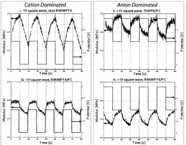
2-13 Isometric testing in BMIMPF6/PC . . . . 46
2-14 Electroactive response under constant and oscillatory strain . . . . . 52
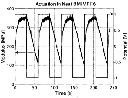
2-15 Modulus response for polypyrrole in neat BMIMPF6 . . . . 53
2-16 Estimated modulus for polypyrrole in different electrolyte solutions 57 2-17 Isotonic response for unprocessed films of different ages.. . . ... 59
3-1 Films deposited from solutions of DBS concentrations, from [1] . . . . 69
3-2 Polypyrrole deposited on different substrates. from [2].. . . . ... 70
3-3 Polypyrrole films deposited onto different working electrodes, from [3] 72 3-4 SEM micrographs of solution side of polypyrrole films. from [4] . . 77
3-5 SEM micrographs of polypyrrole film cross-sections, from [5] . . . . . 80
3-6 Polypyrrole films deposited onto polished and unpolished platinum electrodes, from [6] . . . . 84
3-7 AFM images of polypyrrole films deposited onto polished and unpol-ished copper electrodes, from [7] . . . . 85
3-8 STM images of polypyrrole deposition, from [8] . . . . 86
4-1 Theoretical unit cell.... . . . . . . . 93
4-2 Schematic of scattering experiment . . . . 95
4-3 WAXS patterns for semicrystalline polyethylene [9] . . . . 96
4-4 Comparison of WAXS patterns for stretched polyethylene and stretched polypyrrole . . . . 97
4-5 Diagram of characteristic reflections in stretched polypyrrole . . . . . 103
4-6 Schematic illustration of staggered polypyrrole chains . . . . 104
4-7 Polypyrrole unit cell, as proposed by Nogami et al [10] . . . . 105
4-8 ID diffraction patterns for polypropylene and polypyrrole . . . . 107
4-9 Polpyrrole unit cell as proposed by Geiss et al. [11] . . . . 110
4-10 Helical polypyrrole structure as proposed by Chu et al. [12] . . . 111
4-11 Procedure to make TEM samples from thin polypyrrole films . . . . . 113
4-12 Electron diffraction pattern from thin polypyrrole film . . . . 114
4-13 Electron diffraction patterns from thin polypyrrole film after electron beam exposure . . . . 116
4-1-4 X-ray diffraction of oxidized and reduced polypyrrole film . . . . 120
4-15 X-ray diffraction of severely reduced and re-oxidized polypyrrole film 122 4-16 Separation of curves from Figure 4-15 . . . . 123
4-17 Electron diffraction of as-deposited and reduced polypyrrole samples . 125 4-18 EELS of as-deposited and reduced polypyrrole samples . . . . 127
4-19 Illustration of bundled microstructure in oriented polypyrrole . . . . . 130
5-1 Wide-angle x-ray scattering of unprocessed polypyrrole . . . . 136
5-3 Wide-angle x-ray scattering of rolled polypyrrole . . . . 139
5-4 1D WAXS patterns for stretched and rolled films . . . . 140
5-5 SEM images of processed film fracture surfaces ... 141
5-6 Isotonic response for stretched and rolled films . . . . 142
5-7 Isometric response for stretched and rolled films . . . . 143
5-8 Isotonic testing of stretched samples at different voltage ramps . . . . 144
5-9 Microstructure of polypyrrole chains in as-deposited and processed films146 5-10 Schematic (2-D) diagram of expansion and contraction for oriented films149 5-11 Stretched and rolled films tested 12 weeks after deposition and processing150 5-12 Change in interchain spaces upon oriented polypyrrole actuation in liquid salt . . . . 152
6-1 Sizes of species varied in polypyrrole depositions . . . . 157
6-2 Glassy carbon and nickel foil working electrode surfaces . . . . 158
6-3 Solution-facing surfaces of films from Table 6.1 . . . . 159
6-4 Electrode-facing surfaces of films from Table 6.1 . . . . 160
6-5 ID x-ray diffraction patterns of solvents and films from Table 6.1 . . 162
6-6 Actuation of films with different surface morphologies . . . . 164
6-7 Isotonic actuation of Film G in aqueous solution . . . . 165
6-8 Isotonic actuation of Film G in 60/40 water/PC . . . . 166
6-9 Tensile testing of films from deposition E . . . . 168
6-10 SEM micrographs of films A, E and G . . . . 169
6-11 Isotonic actuation of stretched Film G . . . . 170
6-12 Dry and wet modulus tests for stretched film G . . . . 170
7-1
Illustration of the bundled composite microstructure in as-depositedpolypyrrole
. . . 174
List of Tables
1.1
Properties of different actuator materials, from [13] . . . .
18
2.1 Previous investigations of static modulus in polypyrrole . . . .
49
5.1 Electroactive results for stretched and rolled films . . . .
143
6.1 Conditions for different polypyrrole electrodeposition recipes . . . 156
Chapter 1
Introduction
1.1
Motivation
As engineers develop devices inspired by nature in their function, mechanics, and style. they create a need for new. muscle-like materials to drive these devices. Engines and motors can be made to be very efficient, but they tend to be bulky, inflexible and not always appropriate for biomedical engineering or personal actuator applications. For example, small machines that emulate fish or insect locomotion must be powered by something that is lightweight and flexible. Soldiers, fire-fighters and other first responders are often hindered by having to carry heavy loads into intense situations. Muscle-like actuators incorporated into their equipment to increase their performance and help keep them safe will not be practical if the actuators require very heavy battery packs. noisy combustion engines or continuous access to a stationary power source. Instead, a new technology must be developed that can convert energy to work quietly and efficiently. without the bulky constraints of traditional motors and engines.
To address this need, a range of novel, "artificial muscle" technologies are being developed, some examples of which are presented in Table 1.1. These materials respond to an electrical. thermal or chemical impulse by changing shape. and can be used to move parts in devices in the same way that human muscles move parts of the body. It should be noted that these artificial muscle materials cannot replace
natural muscle, and may never do so. They are so named because they operate in a
muscle-like way, i.e. they operate silently, they are lightweight, flexible, and powerful,
and they consume relatively little energy.
Duplicating the properties of natural muscle is a significant challenge for engineers,
as natural muscle has evolved over thousands of years and is seamlessly coupled with
systems for sensing, energy supply, waste removal, and self-regeneration. However,
much can be learned from the highly specialized nature of muscle, in that it is
nanos-tructured to have exactly the right elements for actuation. The overall goal of this
thesis is to produce an actuator out of synthetic materials that uses a specialized
microstructure to increase its electroactive properties to mimic skeletal muscle.
Active Active Work Peak Strain Effidency
Actuator stress density Rate Advantages Disadvantages
(MWa) (kJ/m") (%)
Has systems for heat and Requires specialized chemical Mammaflan 20 0.35 8 >50 -40 waste removal, energy and thermal environment, not Skeletal Muscle delivery and regeneration synthetically produced
Dielectric Up to 380 ~1 Up to 3400 4,5 Typically 30, Very high strains and High voltages (>I kV) and Elastomers up to 90 strain rates fields (-150 MV/m) required Liquid Crystal 45 in 30 in Large strain for thermal Thernal versions are slow
Elastomers thermal, thermally 75 in electrical materials, fast strains for unless very thin or (thermally or 2-4 in 0.01-0.5 -20 activated, 7nerial electrical. Photo- photoactivated. Electrical
electrically electrical 1000 in activation has hem versions require high fields
activated) materials electrically achieved (1- 25 MV/m)
UP 4 119Lawv0Uag(-2w) Slow(aftentunatseveWaHz: ( sin andspmin toadvie * W2a) Ionic Polymer Low voltage (<10 V), Only useful for bending
Metal 0.5-3 3 up to 5 3 1.5-3 mechanical amplification (not linear) motion Composites gives large displacements
Carbon Large operating
Materials are expensive, active
Nanotube < I up to 30 2 20 0.1 temperture range. strains are very low
Actuators Low voltage.
Thermally Very high power Difficult to control
Activated Shape 5 up to 200 >1000 300 <5 (>100 kW/kg). (run between fully contracted Memory Alloys Low operating voltage and extended but not between)
Table 1.1: Properties of different actuator materials, from [13]. Some materials, such
as dielectric elastomers and liquid crystal elastomers, can achieve very high strains and
strain rates but require large voltages or electric fields to run them. Other materials,
such as ionic polymer metal composites and carbon nanotube actuators, run at much
lower voltages but do not show strains that are comparable to muscle. Polypyrrole
provides a material that runs at a low operating voltage, but still achieves moderate
actuation metrics.
The ideal actuator would not only actuate in a muscle-like way, its metrics would actually exceed mammalian skeletal muscle. It would strain above 20% when actu-ated, but not require more than a few volts to do so. It would be flexible enough to show a large active strain, but stiff enough to provide a large active stress and to be held in tension without excessive creep. It would work at the range of temperatures in which humans live (-20'C to 40*C) and run off of a portable power source. And finally, it would be able to run for millions of cycles without degradation. As shown in Table 1.1, there are currently no technologies that can meet all of these requirements. For example, dielectric elastomers can have exceptionally high strains and efficiencies, but require huge power supplies to run them at voltages of 1 kV or more. This makes them impractical and dangerous for many biological applications. Carbon nanotubes, on the other hand, are lightweight, require very little voltage and show a reasonably high strain rate. Unfortunately, the total active strain achievable is too low for many applications.
The perfect artificial muscle material does not yet exist, but in this thesis we seek to improve our understanding of and the performance achievable by a certain class of actuators: conducting polymers. By studying the connection between microscale structure and macroscale electroactive response, we improve our understanding of conducting polymer actuation and develop methodologies for harnessing that mi-crostructure to improve electroactive response.
1.2
Material Platform
Of the artificial muscle technologies available, conducting polymers such as polypyr-role provide a particularly attractive platform because they are inexpensive to manu-facture ($3/kg). thermally and chemically robust. require very little voltage to operate (1 to 3 V). and have good electroactive properties (Table 1.1). The first conducting polymer. polyacetylene. was first published in 1977 [14] and garnered the Nobel prize in chemistry for Shirakawa. MacDiarmid and Heeger in 2000 [15]. Some other com-monly used conducting polymers are shown in Figure 1-1. Conducting polymers have
conjugated backbones that allow electrons or holes introduced into the backbone via doping to easily travel along the chain. Details about the mechanism of conductivity in conducting polymers will be discuss in Section 3.1.
a. b. C. -N H n n d. e. C6H13 Of S S n n s n
Figure 1-1: Commonly used conducting polymers. a) Polyacetylene (PA). b) Polyani-line (PANI). c) Polypyrrole (PPy). d) Polythiophene (PT). e) Poly(3-hexylthiophene) (P3HT). f) Poly(3,4-ethylenedioxythiophene) (PEDOT).
Actuators made from conducting polymers were first proposed in the early 1990s [15-18], when it was discovered that cycles of oxidation and reduction in an electro-chemical cell led to a volume change and force production. It is interesting to note that at the time, conducting polymers were generally being developed for electronic and battery applications in which a volume change upon charging or discharging was a problem to be overcome. The accepted actuation mechanism for these materials is based on volume changes that result from the uptake or exclusion of counter ions to maintain electro-neutrality during a redox cycle [19,20], and will be discussed in detail for polypyrrole in Section 2.3.
Of the electroactive polymers currently available, polypyrrole and polyaniline have shown the largest, active stresses and strains, and have spawned the most actuator-related research and development. Polvaniline is an interesting actuator candidate because it is more processable than polypyrrole [21.22], but it is used in acidic environ-ments where the pH is below 4.5 [23,24]. Polypyrrole provides a conducting polymer actuator platform that regularly achieves comparable active strains to polyaniline and can be actuated in a variety of less severe environments [13.20.25.26]. Recently. very large metrics (up to 39% maximum strain. over 10% repeatable strain) have
been reported for polypyrrole synthesized [3, 27-29 and actuated [3,30,31] in novel electrolytes. As will be discussed in Chapter 6, we have observed some of these large maximum strains to be transitory and therefore currently impractical for elec-traoctive devices. However, we have observed large (over 10%) repeatable strains for processed films (Section 5.3), and the promise of larger strains with improved pro-cessing remains. The large electroactive metrics, light weight, low operating power and potential for improvement make polypyrrole an attractive candidate for actuator development.
The microstructure of polypyrrole is yet unclear, as will be discussed at length in Chapter 4. Questions typically asked about polymer systems, such as the molecular weight or percent crystallinity, are still unknown for polypyrrole. After it is synthe-sized, polypyrrole is insoluble and unmeltable, rendering many polymer characteri-zation techniques impossible and making it very difficult to manipulate or change its microstructure. Conducting polymers such as polypyrrole can be substituted, copoly-merized or blended with flexible polymers to improve their processability or solubility, but it is difficult to significantly increase their processability via thermal and chemical means without negatively affecting their conductivity [32-39].
Polypyrrole has been extensively studied as an electroactive material, but these studies have provided little elucidation as to the nanoscale mechanisms of actuation and how the morphology accommodates (or hinders) those mechanisms. We believe that, it is imperative to discover and to take advantage of the link between morphology and electroactive performance. Moreover, controlling polymer chain configuration and electronic properties at a sub-micron level will enable development of a superior conducting polymer actuator that shows a larger, faster macroscopic electroactive response.
1.3
Thesis Overview
The first step towards understanding how actuation is controlled by structure is to further elucidate the microstructure of polypyrrole. We have used electrochemistry.
microscopy and x-ray and electron diffraction to probe the micro and nanoscale struc-tural elements that contribute polypyrrole's success as an actuator. The results of these studies are presented in Chapter 2 and Chapter 4. In Chapter 4, we propose a new description of polypyrrole microstructure that explains the diffraction patterns we (and others) observe, as well as polypyrrole's mechanical, electrical, and electroac-tive properties.
We also seek to manipulate the structure of polypyrrole to increase the electroac-tive properties currently observed. It has been previously shown that every aspect of the polypyrrole polymerization conditions (including solvent, dopant, temperature, electrochemical conditions and electrode material) contributes to the morphology of the final polypyrrole product. In order to understand how the material can be changed and what effect these changes may have on actuation, we have reviewed prior stud-ies on polypyrrole production and structure in Chapter 3. Our work to achieve new morphologies by altering the polymerization conditions is presented in Chapter 6.
While altering the deposition conditions can change the polymer film proper-ties significantly. we also seek to improve the properproper-ties of polypyrrole films post-deposition. By mechanically deforming the films to have anisotropic textures (ob-servable by x-ray diffraction) and then measuring the films' electroactive properties, we can observe how different chain arrangements affect the electroactive response. This work has led us to new insights to the nanoscale mechanisms of actuation as well as significant improvements in the magnitude of electroactive response, and is presented and discussed in Chapter 5.
Over the course of this thesis. new insights to polypyrrole structure and the mech-anism of actuation are discussed and methodologies to control structure and improve polypyrrole actuation are presented. These findings are summarized with our sugges-tions for future work in Chapter 7.
Chapter 2
Synthesis and Characterization of
Polypyrrole Actuators
In this chapter. our standard methods for producing and testing polypyrrole films are discussed. to give the reader a context for the polypyrrole actuators we develop. Production of polypvrrole is discussed in Section 2.1 and methodologies for testing conductivity and surface morphology are presented in Section 2.2, to set the stage for the experimental results that will be presented in the following chapters. We test the electroactive properties of our films using a custom-built electrochemical dynamic mechanical analyzer that is described in Section 2.3. along with the testing details and factors influencing the electroactive response. The way that polypyrrole's mechanical properties change during actuation is reviewed and further studied in Section 2.3.8. to improve our understanding of the mechanics of actuation. Finally. the effect of the ageing on polypyrrole actuators is discussed Section 2.3.9.
2.1
Synthesis
Polypyrrole is representative of many conducting polymers in that it can be electri-cally or chemielectri-cally polymerized to make an insoluble, free-standing film. Electropoly-merized polypyrrole typically has a conductivity of to 3 to 5 x 10⁴ S/m. an elastic
N
N
H
H
H H+N
-2H+
/
N
N+ N H H H - HFigure 2-1: Polymerization mechanism for polypyrrole. A typical deposition solution is 0.05 M pyrrole, 0.05 M tetraethylammonium hexafluorophosphate and 1%vol water in propylene carbonate. The polymerization results in a robust, conducting film doped with hexafluorophosphate anions.
2.1.1
Electropolymerization
The most conductive and electroactive pyrrole films are made via electropolymer-ization. The exact mechanism of the polymerization reaction is the subject of de-bate [40], but it is generally believed that a pyrrole monomer is oxidized, forming a cation with several resonance forms. Two cations then come together to form a dimer. This reaction is shown in Figure 2-1 [41,42]. This dimer is then oxidized to form a new cation. and the chain continues to grow. Whether additional pyrrole monomers, dimers or chains are added to the growing chain is not yet well understood. Sadki et al. published a review in 2000 that covered several of the possible mechanisms [40].
Electropolymerization takes place in an electrochemical cell. an example of which is shown in Figure 2-2. Polypyrrole is polymerized from a solution of 0.05 M pyr-role. 0.05 M counterion salt (tetraethylammonium hexafluorophosphate (TEAPF6) or tetrabutylammonium hexafluorophosphate (TBAPF6)). and 1%vol water in propy-lene carbonate. We deposit from a two-electrode cell, with a glassy carbon working electrode and copper foil counter electrode. Films are deposited at constant current (galvanostatically). at 1 A/m2 of working electrode. The entire reaction is conducted at -40'C. to minimize cross-linking and branching of the growing polypyrrole chain.
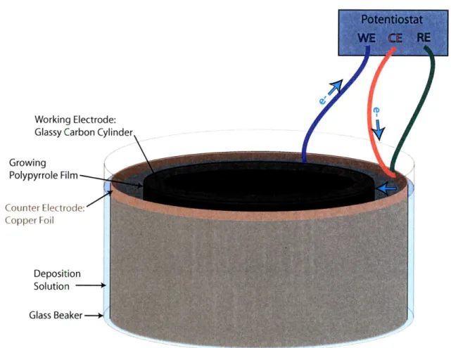
Working Electrode: Glassy Carbon Cylinder Growing Polypyrrole Film Counter Electrode: Copper Foil Deposition Solution Glass Beaker -- +
Figure 2-2: Standard large scale deposition cell. A glassy carbon cylinder (diameter
= 75 mm, height = 100 mm) is used as the working electrode, and placed in the
center of the deposition solution bath. A copper foil is used as the counter electrode and reference electrode. A potential is applied between the working and counter electrodes, such that pyrrole oxidation happens at the working electrode surface. Electron flow is shown with blue arrows.
As the polypyrrole chains grow (and their conjugation increases), their oxidation potential decreases resulting in slightly oxidized polymer chains [40]. Anions from solution are incorporated into the polymer matrix to maintain charge neutrality, re-sulting in a "doped" conducting polymer film at the end of deposition. When using the deposition conditions described here, the film deposits onto the working electrode at a rate of approximately 2 pm/hour. Films used in free-standing actuator appli-cations are typically 10 to 40 pum thick, as thinner films show a faster active strain response but films that are less than 10 pm thick are usually too fragile to handle.
the properties of the polypyrrole film, including the choice of solvent, electrolyte salt, and electrode materials, the geometry of the cell, the deposition temperature, and the potential or current density at which the synthesis is conducted. The conditions pre-sented above are our "standard" polypyrrole deposition conditions, and are used for all films in this thesis unless specified otherwise. The effects that changing deposition parameters have previously shown on the morphology and microstructure of polypyr-role films is discussed in Chapter 3, while our work towards better understanding of how the different morphologies affect actuation is discussed in Chapter 6.
2.1.2
Chemical Polymerization
Polypyrrole can also be synthesized via chemical polymerization, using a chemical oxidant such as FeCl3 [43,44]. During chemical polymerization, pyrrole and a
water-soluble counterion salt are added to an aqueous FeCl3 solution. The FeCl3 initiates
pyrrole polymerization, and the black polymer falls out of solution. This method can be used to coat fabrics or other non-conducting surfaces with polypyrrole, as the polypyrrole will deposit on any surface exposed to the reaction solution.
Alternatively. anhydrous FeCl3 can be dissolved in an organic solvent. When
pyr-role is mixed into this solvent, it will be oxidized, and the resulting polypyrpyr-role will precipitate out of solution. Both methods of chemical polymerization produce pow-dery products that are not free-standing, and are generally used when one wants to coat, a non-conductive surface [43-45] or to make polypyrrole with a very large surface area for capacitor applications [46,47]. Because free standing films are necessary for actuator applications, this work focuses on polypyrrole produced electrochemically.
2.2
Film Quality
There are several metrics by which one can measure the quality of electropolymer-ized polypyrrole. but two of our most commonly used checks include the electrical conductivity and surface morphology. Conductivity is measured as an indication of the polymer's electronic properties and robustness. while surface morphology has
im-plications in both the speed and magnitude of the electroactive response. The two are often linked, in that the films with the highest conductivity tend to have the smoothest surfaces. Chapters 3. 5 and 6 discuss the ways in which conductivity and surface morphology have been observed to influence actuation at length, but here we discuss the techniques used to measure and understand these properties on their own.
2.2.1
Conductivity Measurements
When polypyrrole is synthesized electrochemically, the chains are left slightly oxi-dized. Approximately one out of every three monomers has a positive charge, sup-ported by a counterion [48,49]. One should note that these counterion dopants are different from substitutional dopants in more traditional semiconductors, as they are separate from the polymer backbone and simply donate or accept charges from the polymer chains
[50].
Charges (in the case of polypyrrole, holes) can easily move along the polymer chain. due to the delocalized nature of the electronic orbitals. Because no single polypyrrole chain is long and straight enough to transverse an entire bulk sample, the positive charges must "hop" between chains to move across the sample and give the material a measurable bulk conductivity [51]. It is easier for charges to move along the polymer chain than to hop between chains. The conductivity of the bulk conducting polymer same will increase with increasing conjugation length [52.53] and polydispersity of conjugation lengths [52], as both allow charges to traverse more of the sample along a polymer backbone. The detailed nature of polypyrrole's con-ductivity will be discussed in Section 3.1.The conductivities of polypyrrole samples are measured using a standard four-point, probe connected to an Agilent 3441A 61 Digit Multimeter. In a four-point probe measurement. one contacts the sample with four point leads in a straight line. A constant current is applied to the two outer leads and the potential drop is measured by the inner leads. When using the multimeter. the measurement is read as resistivity (measured voltage over applied current). Conductivity is typically calculated via the following equation:
ln(2)
o- =
7r Rt-
(2.1)where u is conductivity in S/m. R is the resistivity as measured with the four point probe, and t is the thickness of the sample. However, Equation 2.1 assumes that the width of the sample is 3 to 4 times the distance between the inner leads. In our case, samples are cut to be 10 - 20 mm long x 1 - 2.5 mm wide in order to capture any anisotropy that may have been induced into the sample (Chapter 5). The leads on the four point probe are only 2.5 mm apart. so the assumption that the width of the sample is much greater than that between the leads is no longer valid. To account for this, we use the following equation:
d
a =(2.2)
Rtw7
dwhere d is the distance between the inner leads, and t and w are the thickness and width of the polymer sample. While it is not the standard equation for four point probe measurements, Equation 2.2 has been shown to be quite accurate as long as u is smaller than d
[54].
Unprocessed electropolymerized polypyrrole typically has conductivities of 3 to 5 x 10' S/m. while oriented samples can have conductivities up to 1 x 10⁵ S/m. Work towards achieving high degrees of orientation in polypyrrole and its effect on conductivity are discussed in Chapter 5.2.2.2
Surface Morphology Evaluation
Depending on the polymerization conditions, the surface morphology of polypyrrole can vary from smooth and featureless to a rough. nodular morphology. as shown in Figure 2-3. In some cases both morphologies will be observed on the same film. as the electrode side is smooth while the solution side is rough and nodular. The effect of polymerization conditions on surface morphology is discussed in Chapter 3. and our work towards manipulating surface morphology to improve electroactive response is discussed in Chapter 6. To some extent. one can infer the surface morphology of polypyrrole simply by visually examining the film. While the surface features are too
Figure 2-3: Solution and electrode faces of nodular polypyrrole film. A small flap of
film has curled back and is observable in the foreground. The bumpy surface
observ-able in the background and on the flap of film is the solutioni face of the polypyrrole
film. The smooth surface observable on the flap of film in the foreground is the
electrode face. Microscopy was conducted on an FEI/Philips XL30 FEG ESEM. A
voltage of 10 kV and spot side of 2.0 were used. The ESEM was run in environmental
mode, and no gold coating of the film was necessary.
small to be discerned by eye, a smooth film will appear shiny under ambient light
while a nodular film will appear matte. For more detail on the microscale features
that produce this effect, we turn to scanning electron microscopy (SEM).
Electron microscopy of polymeric samples is particularly difficult, as the electron
beam can ablate the sample during imaging. Because polymeric materials are
gener-ally insulating, there is no mechanism to dissipate the electrons hitting the sample,
leading to localized charging and radiation damage. Polypyrrole is more resistant
to electron beam damage than non-conductive polymers, as its conjugated structure
allows charge to dissipate. However, at slow scan rates, high magnifications, and in
samples of particularly low conductivity, beam damage is often evident (Figure 2-4).
Care must be taken to avoid scanning the same area for extended periods of time in
order to keep beam damage to a minimum. One alternative is to focus the microscope
on one area of the sample, then quickly move the sample and image an adjacent area.
As long as the sample height remains constant (so the new area is also in focus) this
allows one to avoid imaging areas that have been damaged by focusing. Additionally,
a thin (-10 A) coating of gold can be sputtered onto the sample to help dissipate
charge and prevent sample damage during imaging.
Figure 2-4: Beam damage in polypyrrole sample. Micrograph taken on JEOL
JSM-5910 with an accelerating voltage of 5 kV and a spot size of 20. Beam damage is
evident in rectangle marked by pink lines. The dark region is due to a lower yield
of secondary electrons that may be caused by polymerization of pump oil (deposited
onto the sample when the chamber was pumped down) by the electron beam.
For this work, scanning electron micrography was conducted on three instruments:
an FEI/Philips XL30 FEG ESEM, a JEOL JSM-5910, and a JEOL JSM-6060.
Op-erating voltages were typically between 10 and 20 kV, and spot size was 2.0 for the
XL30 and typically 20 to 40 for the 5910 and 6060. The polypyrrole samples were
conductive enough that gold coating of the polypyrrole film was seldom necessary.
2.3
Electroactive Response
Because the goal of this thesis is to increase microstructural understanding and control
in order to produce a better actuator, the ultimate measure of polypyrrole film quality
is how well it actuates. During actuation, polypyrrole is either oxidized or reduced in
the presence of a mobile electrolyte, and ions are incorporated or expelled from the
bulk polymer in order to maintain charge neutrality. This incorporation or expulsion
results in a net volume change or change in stress state of the polymer. The effect of
morphology on actuation is described in Chapter 3, while our work towards improving
electroactive response is presented in Chapters 5 and 6. The methods of electroactive
testing and typical results for polypyrrole actuators are described here.
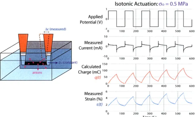
We probe polypyrrole's electroactive response either isotonically
[55-57],
where
the polymer is actuated under constant load and its length change is monitored, or
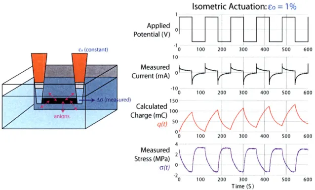
isometrically
[58,59,
where the polymer is held under tension at a constant length and
the change in stress upon actuation is monitored. We conduct both testing methods
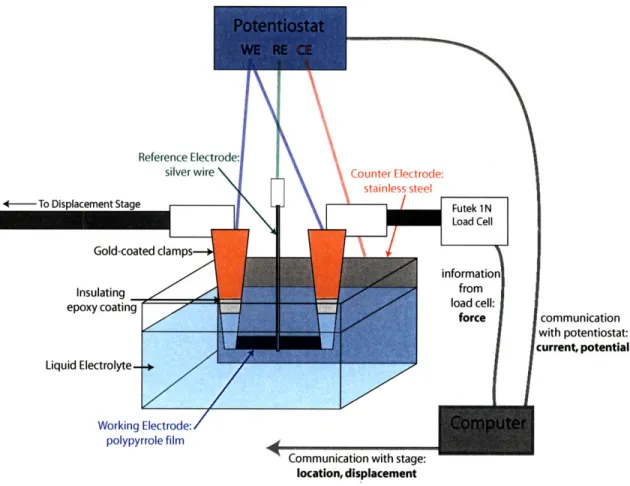
in a custom-built electrochemical dynamic mechanical analyzer (EDMA), a diagram
of which is shown in Figure 2-5
[59].
In this apparatus a small
(~
5 mm x ~ 2 mm)
polypyrrole film is held at constant length (isometric) or constant force (isotonic)
while submerged in a liquid electrolyte bath. The film is clamped in two gold-coated
clamps, the outsides of which are covered in insulating epoxy to avoid leakage current
in the electrochemical cell. One clamp is connected to a Futek 1 N load cell used
measure the stress in the polymer, and the other is connected to an Agilent linear
stage used to apply tension and measure displacement. Both clamps are used to make
an electrical connection between the polypyrrole film and the potentiostat.
The polypyrrole film serves as the working electrode in the electrochemical cell,
and is accompanied by a counter electrode (often stainless steel foil) and reference
electrode (silver wire). An AMEL 2053 potentiostat is used to apply a user-specified
potential waveform between the working and counter electrodes. The applied
po-tential is measured with the reference electrode. A computer is used to control the
potentiostat and linear stage, as well as to take current and potential data from the
To Displacement Stage force communication with potentiostat: current, potential Liquid Electrolyte-+ Working Electrode: polypyrrole film
Communication with stage: location, displacement
Figure 2-5: Electrochemical Dynamic Mechanical Analyzer (EDMA). The polypyrrole
acts as the working electrode in a three-electrode cell, and a potential is applied
across the cell by the potentiostat. Linear change in volume or stress state due to ion
incorporation or expulsion into the polypyrrole matrix is measured by the load cell
and linear stage.
potentiostat, displacement data from the stage, and force data from the load cell.
The apparatus is controlled by running custom-built software [59].
2.3.1
Warm-up
Before beginning an isometric or isotonic test, a "warm-up" procedure is conducted
to measure the state of the film and ensure that all tests are conducted on comparably
swollen films. This procedure also allows one to be sure the active strain measured
is not contaminated by the initial uptake of solvent that may occur upon submersion
in an electrolyte. This initial uptake can be significantly larger than the repeatable
electroactive response, as will be discussed in Section 6.4.1. Immediately after the film
is loaded into the apparatus (before submersion in the electrolyte) its passive elastic
modulus is measured by the application of three cycles of 1% strain at a frequency of
1 Hz. The elastic modulus is calculated as the slope of the stress vs. strain curve, and
referred to as the "dry" elastic modulus. Figure 2-6i shows the dry modulus for films
deposited from propylene carbonate solution. As the black and blue curves in Figure
2-6i show, samples can be stored unsealed for several weeks without an appreciable
change in modulus. A significant amount of propylene carbonate (up to 30%wt)
remains in the films after deposition, and can remain even after several weeks due to
its very low room temperature vapor pressure (40 Pa)'. If the film is subjected to
vacuum, this residual propylene carbonate is removed and the dry modulus increases
(Figure 2-6i, red curve).
A change in deposition recipe may change the dry modulus, as will be discussed in
Chapter 6. This change is apparent when comparing the blue curves in parts i and ii
of Figure 2-6. The blue curve in Figure 2-6i is from a film deposited from a propylene
carbonate solution, and has a modulus of 670 MPa. The blue curve in Figure 2-6ii
is from a film deposited from a methyl benzoate solution and has a modulus of 765
MPa. This difference may be due to the higher room temperature vapor pressure
of methyl benzoate (130 Pa)', which causes more of the residual solvent in the film
to evaporate. If a dry film deposited from methyl benzoate solution is soaked in
propylene carbonate solution prior to testing, the modulus drops far below that of
the standard film (Figure 2-6i, black curve: modulus
=
100 MPa).
After the dry passive modulus is measured, the linear stage moves the clamps
towards each other until the film is slackened, and the bath is raised to submerge
the film into the electrolyte without removal from the clamps. A triangle potential
waveform is applied until the current response stabilizes. At this point the film is
considered to be in steady state condition for the applied electrochemical conditions.
An example of the electrochemistry after warm-up in a solution of 0.1 M Lithium
bis(trifluoromethanesulfonly)imide in propylene carbonate (LiTFSI/PC) is shown in
i. Dry moduli of TBAPF6/PC films
0 0.2 0.4 0.6 0.8 1
Strain (%)
ii. Dry moduli of LiTFI
12 18 '6-0 0 0.2 0.4 0. Strain (%)
Figure 2-6: Passive modulus measurements for polypyrrole samples. i) Comparison
of passive modulus in films synthesized from the standard deposition recipe. Blue
curve: film tested one week after deposition. Modulus
=670 MPa. Black curve: film
tested five weeks after deposition. Modulus
=
670 MPa. Red curve: film tested five
weeks after deposition, after exposure to vacuum (94 kPa) for 15 hours. Modulus
=
1180 MPa. ii) Comparison of passive modulus in films synthesized from 0.2 M
pyrrole, 0.2 M Lithium bis(trifluoromethanesulfonly)imide (LiTFSI) in Methyl
Ben-zoate. Blue curve: film tested four weeks after deposition. Modulus
=
765 MPa.
Black curve: film tested four weeks after deposition after soaking overnight in 0.1 M
LiTFSI/PC Modulus
=
100 MPa. Pink curve: soaked film after "warm-up" in 0.01
M LiTFSI/PC/H20. Modulus
=
90 MPa.
SI/MB films
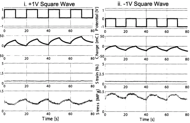
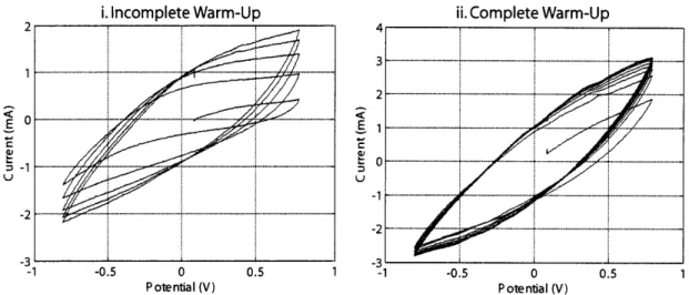
i. Incomplete Warm-Up ii. Complete Warm-Up I | A
![Figure 2-10: Relative sizes [69] of species in an anion-dominated electrolyte system.](https://thumb-eu.123doks.com/thumbv2/123doknet/14091881.464843/41.918.193.743.696.911/figure-relative-sizes-species-anion-dominated-electrolyte.webp)
![Figure 2-11: Relative sizes [69] of species in a cation-dominated electrolyte system.](https://thumb-eu.123doks.com/thumbv2/123doknet/14091881.464843/42.918.186.745.139.343/figure-relative-sizes-species-cation-dominated-electrolyte.webp)