Computer Science and Artificial Intelligence Laboratory
Technical Report
m a s s a c h u s e t t s i n s t i t u t e o f t e c h n o l o g y, c a m b r i d g e , m a 0 213 9 u s a — w w w. c s a i l . m i t . e d u
MIT-CSAIL-TR-2011-013
March 14, 2011
BOOM: Broadcast Optimizations for
On-chip Meshes
Tushar Krishna, Bradford M. Beckmann, Li-Shiuan
Peh, and Steven K. Reinhardt
BOOM: Broadcast Optimizations for On-chip Meshes
Tushar Krishna
†, Bradford M. Beckmann
⋆, Li-Shiuan Peh
†, and Steven K. Reinhardt
⋆†
Department of EECS
Massachusetts Institute of Technology
{tushar, peh}@csail.mit.edu
⋆
Research and Advanced Development Labs (RADL)
Advanced Micro Devices (AMD) Inc.
{Brad.Beckmann, Steve.Reinhardt}@amd.com
Abstract— Future many-core chips will require an on-chipnetwork that can support broadcasts and multicasts at good power-performance. A vanilla on-chip network would send multiple unicast packets for each broadcast packet, resulting in latency, throughput and power overheads. Recent research in on-chip multicast support has proposed forking of broad-cast/multicast packets within the network at the router buffers, but these techniques are far from ideal, since they increase buffer occupancy which lowers throughput, and packets incur delay and power penalties at each router. In this work, we analyze an ideal broadcast mesh; show the substantial gaps between state-of-the-art multicast NoCs and the ideal; then propose BOOM, which comprises a WHIRL routing protocol that ideally load balances broadcast traffic, a mXbar multicast crossbar circuit that enables multicast traversal at similar energy-delay as unicasts, and speculative bypassing of buffering for multicast flits. Together, they enable broadcast packets to approach the delay, energy, and throughput of the ideal fabric. Our simulations show BOOM realizing an average network latency that is 5% off ideal, attaining 96% of ideal throughput, with energy consumption that is 9% above ideal. Evaluations using synthetic traffic show BOOM achieving a latency reduction of 61%, throughput improvement of 63%, and buffer power reduction of 80% as compared to a base-line broadcast. Simulations with PARSEC benchmarks show BOOM reducing average request and network latency by 40% and 15% respectively.
I. INTRODUCTION
As multi-core processors scale to higher core counts, designing a scalable on-chip cache subsystem has become a crucial component in achieving high-performance. Together the cache coherence protocol and on-chip network must be designed to achieve high throughput and low latency, without over-burdening either component. At one end of the protocol design spectrum are full-bit directory protocols [1], [2] which track all sharers, thereby minimizing the bandwidth demand on the network by ensuring that requests only probe the current sharers, while invalidates occur via precise multi-casts. However, full-bit directories require substantial storage overhead per block to manage many individual cores and caches, which increase power and area demands as core counts scale. The other end of the spectrum belongs to snooping protocols [3], [4], [5]. These designs do not require any directory storage, but instead broadcast all requests and invalidates, which significantly increases network bandwidth demand. Many recently proposed coherence protocols and optimizations [6], [7], [8], [9], [10], [11] lie in between to better balance network bandwidth demand and coherence state storage. These designs incorporate coarser directory state to consume less storage than a full-bit directory, and
rely on a combination of broadcasts, multicasts, and direct requests to maintain coherence. Though these protocols re-duce the overall network demand versus snooping protocols, efficient delivery of broadcasts and dense multicasts are critical for their scalability. For instance, despite filtering redundant broadcasts in the network, INCF [8] still observes 58% requests being broadcasts on average using Token Coherence [5] and INSO [4] for the PARSEC benchmark suite [12] running on 16 cores. VCTM [13] reports 10% multicast traffic in a coarse Region-based directory coher-ence scheme with 16-cores with many destinations more than 50% of the time. This would become worse as core counts scale. For a 64-core system, we observe that the AMD HyperTransportTM[3]-based protocol (which normally broadcasts all requests), even when enhanced with HT As-sist [6] to track the Owner and only send directed probes, still relies on broadcast probes for 38-50% of the requests, as we show later in Section IV. All these observations put the on-chip network in the limelight to ultimately handle these many-destination messages at low latency and high throughput, while taking up low area and power overheads. An on-chip network is the communication fabric connect-ing the various cores. An ideal communication fabric would incur only wire delays between the source and destination core. But dedicated global point-to-point wires between all cores do not scale [17], and hence, networks that multiplex and share wires [18] are widely accepted to be the way forward. Meshes are often used as the topology since they map well to physical layout, enabling short wire delays and high throughput. The routers at mesh intersections manage contention and enable effective sharing of the wires. Fig. 1(a) shows such a router. Multicast messages, however, add tremendous stress on the network. A network with no multicast support forces the sender to use multiple unicast packets, effectively forking packets at the source network interface, an approach we term “fork@nic”. Each multicast packet with M destinations thus floods the network with M packets, leading to a dramatic rise in average packet latency and loss in throughput. Recent works such as VCTM [13], Multicast Rotary Router (MRR) [14], and bLBDR [15] address this issue by proposing routers with the ability to fork flits1, i.e. a single multicast packet enters the network, and where the route forks out of multiple output ports towards the destinations, multiple flits are replicated and sent out of each output port. We term this “fork@rtr”.
Switch Allocator VC Allocator Route Compute 5x5 Crossbar switch Input 1 Output 1 Output 5 VC 1 Input buffers VC 2 VC n Buffer Write Routing Input 5 VC 2 VC n VC 1 Input buffers Switch Alloc VC Alloc Switch Traversal Link Traversal
(a) Baseline Router Microarchitecture
0 50 100 150 200 250 300 350 400 0 0.2 0.4 0.6 0.8 1 A v e ra g e B ro a d c a s t L a te n c y
Injection Rate (packets/cycle)
BASE_fork@nic BASE_fork@rtr-XYtr BASE_fork@rtr-ring IDEAL Latency Gap Throughput Gap
(b) Latency and Throughput Gap
0 1 2 3 4 5 6 7 8 9 0.064 0.192 0.32 0.448 0.576 0.704 N e tw o rk En e rg y (n J/ c y c le )
Injection Rate (packets/cycle)
BASE_fork@nic BASE_fork@rtr XYtr BASE_fork@rtr ring IDEAL
Energy Gap
(c) Energy Gap
Fig. 1. Baseline Broadcast Networks (fork@nic, fork@rtr (modeled similar to VCTM [13], MRR [14], bLBDR [15] and RPM [16]) with tree-based route and logical ring route) vs. Ideal (derived in Table I)
While these techniques do improve performance and power, they are still far from ideal (analyzed in Section II), especially for broadcasts, as Figs. 1(b) and 1(c) demonstrate (see Section IV for simulation setup). These state-of-the-art fork@rtr multicast routers are unable to approach the ideal limit due to routing, micro-architecture/circuit, and flow-control limitations, which will be discussed and tackled in Sections III-A, III-B, III-C respectively.
In this work, we propose BOOM (Broadcast Optimiza-tions for On-chip Meshes) as a move towards the ideal network fabric for broadcast and multicast messages. BOOM comprises three techniques that together enable broadcasts and multicasts to closely approach ideal energy-delay-throughput:
• Routing: We introduce the WHIRL routing algorithm that ideally load balances broadcast traffic across a mesh, then prunes this broadcast tree dynamically to match the multicast destination set.
• Router Microarchitecture/Circuit: We introduce a mul-ticast crossbar circuit, mXbar, that enables flits to fork out and be sent simultaneously out of multiple output ports, at similar energy-delay as a unicast.
• Flow control: BOOM extends unicast bypassing of buffer read/writes for broadcast and multicast flits at routers at all loads, making single-cycle router pipelines possible for broadcasts/multicasts.
Section 2 derives the latency, throughput and energy limits for an ideal broadcast mesh. Section 3 details BOOM, discussing related work for every component. Section 4 presents our evaluation, and Section 5 concludes.
II. IDEALBROADCASTMESH
In this section, we derive the ideal latency, throughput, and power metrics for a mesh, for broadcast traffic, which would then set design goals for BOOM. There has been prior work in this regard for unicast traffic (one destination) [19], [20], but to the best of our knowledge no one has attempted to analyze and design for these limits for broadcast traffic.
An ideal interconnection network is that which delivers the best possible throughput at lowest possible latency and energy within physical constraints. A point-to-point network with wires connecting each core to every other core would satisfy this definition. However, such a topology is not
feasible as core counts scale, as there will be insufficient wiring to accommodate the interconnections within a realistic die area [19]. A practical topology for on-chip networks is a mesh, as it is scalable, easy to layout, and offers path diversity. A mesh has theoretical limits of latency, energy and throughput under different traffic constraints, assuming ideal routers.
In Table I, we derive these limits for a k×k mesh for broad-cast traffic2, injected from randomly distributed sources, and contrast them with those for unicast uniform-random traffic [21].
Some of the key insights from Table I are: (1) For k< 4, the throughput of both the fork@nic and fork@rtr broadcast techniques are theoretically limited by the ejection links. For k> 4, however, fork@nic is expected to have k/4 times lower theoretical throughput3, as its bisection links become the bottleneck, while ejection links continue to remain the limiting factor for fork@rtr. This is unlike unicast traffic, which is always limited by the bisection links. (2) When k< 4, pure unicasts have k2 times higher throughput than broadcasts, whereas when k> 4, unicasts have just k times higher throughput than broadcasts. (3) A broadcast-tree not only has lower latency than a broadcast-ring, it also loads its bisection links at half that of a broadcast-ring. However, in practice, the broadcast-tree results in more flits congesting at a router at the same time, which causes hotspots and degrades throughput.
III. BOOM: BROADCASTOPTIMIZATIONS FORON-CHIP
MESHES
A. Routing: The WHIRL Algorithm
1) Background: Multicast packets are typically routed in a path-based or tree-based manner4. In path-based
rout-ing, a multicast packet is forwarded sequentially from one destination to the next. For multicasts with few destina-tions, this presents the problem of selecting a deadlock-free,
2All estimates are for a complete broadcast: from initiation at the source
NIC (network interface), till the tail flit of the last copy of the packet is received at a destination NIC
3Throughput is inversely proportional to channel load [21]. In practice,
k times extra flits in fork@nic would cause extra contention and lower throughput even further
4In Table I, path-based routing is broadcast ring and tree-based routing
TABLE I
Ideal Performance and Power metrics in a k×k mesh with N = k2 tiles.. WE COMPARE UNIFORM-RANDOM DESTINATION UNICAST TRAFFIC,AND ALL-DESTINATION BROADCAST TRAFFIC,INJECTED FROM RANDOM SOURCES AT A RATE OFRFLITS/CYCLE.
Metric Unicast Broadcast
Average Hop Count or Havg 2(k + 1)/3 (3k − 1)/2, k even
(k − 1)(3k + 1)/2k, k odd
Channel Load on each bisection link or Lbis k×R/4 ⋆k3×R/4,†k2×R/4,‡k2×R/2
Channel Load on each ejection link or Le je R k2×R
Ideal Latency 2(k + 1)/3×Trr+ 2×Trn (3k − 1)/2×Trr+ 2×Trn, k even
Tr(r/n): Delay of router-(router/nic) traversal links (k − 1)(3k + 1)/2k×Trr+ 2×Trn, k odd
Ideal Throughput R, k< 4 and k×R/4, k > 4 ⋆k2×R, k < 4 and⋆k3×R/4, k > 4
(max{Lbis, Le je}) †‡k2×R
Ideal Energy 2(k + 1)/3×Exbar + Exbar + N×Exbar +
Er(r/n): Energy of router-(router/nic) traversal links 2(k + 1)/3×Err+ 2×Ern (N − 1)×Err+ N×Ern
Exbar: Energy of crossbar-switch within router
Ideal Latency for broadcasts is the hop delay of the furthest destination router, averaged across all sources. If we divide a mesh into four
quadrants, the furthest destination for any router in a particular quadrant, is the corner router in the opposite quadrant. We compute the average hop count across all sources in a quadrant, and multiply it by four. This hop count is then translated to cycles, by assuming single-cycle routers, and T rr cycles between routers in links.
Ideal Energy for broadcasts is computed by multiplying the average hop count by the ideal energy of each hop, which is just the energy of the datapath
(crossbar and links).
Ideal Throughput for broadcasts is analyzed by evaluating the channel load across the bisection links and ejection links [21].
⋆fork@nic (network interface forks flits): an injection rate of R flits/cycle translates to k2×R unicast flits entering the network.
†fork@rtr broadcast-tree (routers fork flits based on an ideal tree-based route), all flits in one half of the network (k2×R/2) cross to the other side; half
go straight along X and fork into multiple flits along Y, half go straight along Y and fork into multiple flits along X. Each of these flits, once forked, makes k/2 bisection crossings per direction.
‡fork@rtr broadcast-ring (a single packet traverses a logical ring in the network), all flits in the network (k2×R) cross to the other half, and then return
to the same half in alternate rows/columns, resulting in k/2 bisection crossings per direction per flit.
shortest-path route. For multicasts with many destinations, and broadcasts, this leads to the packet traversing a logical ring embedded in the network, and forking out to the NIC at each destination router. This results in hundreds of cycles of latency for the destinations at the end of the ring, and is thus not a scalable solution.
Tree-based routing creates multicast trees in the network, and are used in most works. Multicast trees however add the complexity of either storing the tree information in the network, or creating them dynamically. Many previous works such as VCTM [13], MRR [14], Samman et al. [22] use the former approach and use routing tables at routers, which add area, power and delay overheads [21]. bLBDR [15] and RPM [16] avoid routing tables and use combinational logic to create trees. bLBDR partitions the network into different domains using connectivity bits and broadcasts within them, while RPM uses priority rules to dynamically determine routes based on the quadrants relative to a router where destinations lie.
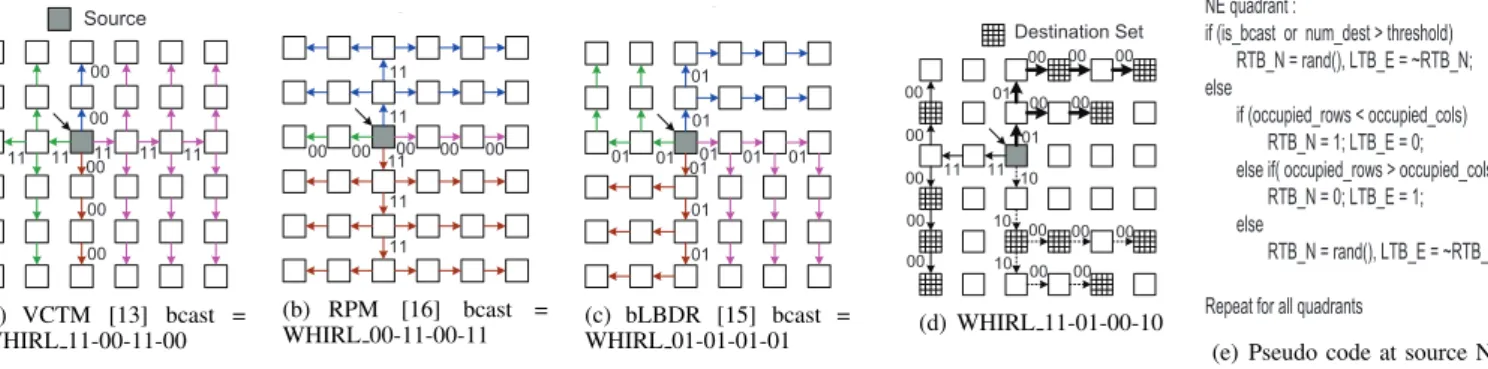
However, a major limitation of all these schemes is that their various multicast-trees reduce to one tree in the pres-ence of broadcasts, or multicasts with very dense destination sets. The reason for this is that conflicts for choosing paths are broken by using fixed output port priorities. This is required to avoid duplicate reception of the same packet via alternate routes. Fig. 2 shows the trees that all broadcast flits in the network would use in some of these works, based on the rules specified in each of them. The downsides of this are that the links are utilized in an unbalanced manner, lowering throughput5. For broadcasts in an 8x8 mesh, we observed that VCTM uses X-links 11%, and Y-links 89% of the time. RPM does the exact opposite.
5The average number of flits crossing the bisection links now becomes
non-uniform in each direction, instead of uniformly being k/2 like the ideal load-balanced tree discussed in Table I
To the best of knowledge, there has been no routing scheme that targets broadcasts/dense multicasts, and achieves ideal load balance.
2) WHIRL: We propose a tree-based routing scheme called WHIRL that (1) achieves load-balancing for broad-casts and dense multibroad-casts, (2) guarantees non-duplicate packet reception, (3) is non table-based, and (4) is deadlock-free.
Previous approaches create multicast-trees from unicast paths. We adopt the opposite approach: we create multicast-trees from a global load-balanced broadcast-tree. For mul-ticasts with few destinations, our approach and previous approaches would yield similar results, but as the desti-nations increase, our approach would outperform previous approaches due to more path diversity.
WHIRL utilizes just two-bits to encode the routing in-formation: the LeftTurnBit (LTB) and RightTurnBit (RTB). These signify whether the flit should turn left, or turn right, relativeto its current direction of motion6. Combinations of these bits across all directions, subject to certain restrictions creates the global WHIRL tree. This tree is then pruned at network routers based on the multicast destination locations.
Source NIC: Choosing the WHIRL route. The global
WHIRL route which would be taken by a multicast/broadcast packet is decided by the source network interface (sNIC), i.e. source routing. This is done not only to balance the load, but also to ensure non-duplicate and guaranteed reception of packets at all destinations’ network interfaces (dNIC); which is hard to support if the routers dynamically decide which route to take. The sNIC chooses four pairs of (LTB, RTB), one for each direction. These bits need to adhere to the following two rules to ensure non-duplicate packet delivery: (1) If the LTB of a particular direction is high, the RTB of the direction to its left cannot be high, and
Source 00 00 00 00 00 11 11 11 11 11 (a) VCTM [13] bcast = WHIRL 11-00-11-00 00 11 00 00 00 00 11 11 11 11 ... (b) RPM [16] bcast = WHIRL 00-11-00-11 ... 01 01 01 01 01 01 01 01 01 01 (c) bLBDR [15] bcast = WHIRL 01-01-01-01 Destination Set 11 11 01 01 10 10 10 00 00 00 00 00 00 00 00 00 00 00 00 00 00 00 (d) WHIRL 11-01-00-10 NE quadrant :
if (is_bcast or num_dest > threshold) RTB_N = rand(), LTB_E = ~RTB_N; else
if (occupied_rows < occupied_cols) RTB_N = 1; LTB_E = 0; else if( occupied_rows > occupied_cols)
RTB_N = 0; LTB_E = 1; else
RTB_N = rand(), LTB_E = ~RTB_N Repeat for all quadrants
(e) Pseudo code at source NIC Fig. 2. Some WHIRL broadcast trees. Packets fork into all four directions at the source router. By default, every packet continues
straight in its current direction. In addition, forks at intermediate routers are encoded by [LeftTurnBit, RightTurnBit], where left and right are relative to the direction of traversal. These bits are reset to 0 once a turn completes (hence 00 is implicit on all unmarked arrows).
(2) If the RTB of a particular direction is high, the LTB of the direction to its right cannot be high.
This results in a total of 16 possible WHIRL trees. Some of these are shown in Fig. 2. The trees from VCTM [13], RPM [16] and bLBDR [15] form a subset of our WHIRL broadcast trees.
If the total number of destinations are above a threshold7, LTB and RTB for each direction are chosen randomly (to enable path diversity), subject to the 2 constraints mentioned above, and one of the 16 WHIRL trees will result. If they are below the threshold, they are chosen to try and maximize the number of destinations along the route. We implement a heuristic where we count and compare the total occupied rows and columns in each quadrant, and choose LTB/RTB such that the flit goes along the X direction, and forks into Y, if the number of occupied rows is higher, and vice versa. An example of this can be seen in Fig. 2(d). Our pseudo code is shown in Fig. 2(e), and this component in the source NIC has a critical path of 480ps in 90nm when synthesized from RTL.
The sNIC sends the four sets of (LTB, RTB) values, one for each direction (8 bits in a mesh); along with the actual outport request (a 5-bit vector with multiple bits high), to the router it is connected to.
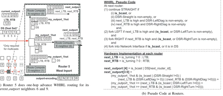
Routers: Implementing WHIRL’s LTB and RTB. WHIRL
is implemented as a one-hop-in-advance lookahead rout-ing [23] mechanism, to remove route computation from the critical path. This also enables buffer bypassing, which will be discussed later in Section III-C. This means that every flit that enters a router already knows its output ports (including the one entering from the sNIC). These output port requests are sent as one-hot encoded values to separate WHIRL route compute modules, one for each output port8 that the
flit wishes to fork out of, as shown in Fig. 3(a). One-hot encoding allows us to implement left turns and right turns by simple left-shift and right-shift operations respectively, simplify the route computation circuit.
The pseudo code for each WHIRL route compute unit is shown in Fig. 3(b). It has a critical path delay of
7We set the threshold to 16 for a 8x8 mesh, based on experiments 8For a P-port router, WHIRL requires (P-2) modules at each input port
(assuming no u-turns, and no advance routing required for the NIC), and (P-1) modules at the NIC
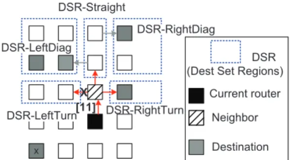
380ps in 90nm, fitting within a 2GHz clock. At each route computation circuit, (LTB, RTB) values for the next router are determined. If the flit is turning, these bits are reset to zero, else they remain the same as the current value. These new values determine the output ports at the next router. For broadcasts, continuing straight is implicit, while next LTB and/or next RTB values being high determines if the flit needs to turn left and/or right at the next router. For multicasts, however, routers need to ensure that flits do not fork into rows/columns which do not contain nodes in their destination sets. This filtering is performed with combinational logic, without using routing tables. We assume that multicast flits carry a destination set bit-string, similar to that in RPM [16]. In our design, the destination bit-string gets divided into five Destination Set Regions (DSR) bit-strings, during the route computation, based on the position of the neighbor router for which the routing is being performed, as shown in Fig. 4(a). These regions are called DSR-LeftTurn, DSR-LeftDiag, DSR-Straight, DSR-RightDiag and DSR-RightTurn. Unlike broadcasts, the decision to continue straight, turn left, and turn right depends not just on the next LTB/next RTB, but also on the occupancy of each DSR, as highlighted in Fig. 3(b). Note that the same destination node will lie in different DSRs for different neighbors of the same current router. This is not a problem, because the LTB/RTB rules described earlier in Section III-A.2 will ensure that the destination is reachable from only one of the neighbors. For the same reason, bits in the destination-set bit-string do not have to be reset as the flit moves through the network, like in RPM [16], thereby simplifying the circuitry further.
Throughput Characterization. Packets traversing all of WHIRL’s 16 broadcast trees utilize all possible X+, X-, Y+ and Y- links that lie along the minimal routing path. This is because WHIRL does not add any fixed direction priorities, and instead guarantees non-duplicate reception via the LTB/RTB rules discussed earlier. For pure broadcast traffic, simulations showed an ideal 50% utilization on both the X and Y links. From a theoretical perspective, each injected broadcast flit results in k/2 crossings of the bisection along each direction, which is the ideal channel load, as derived in Table I.
8 9 4 5 6 0 1 2 7 3 Route Compute N-neighbor (9) 1 1 1 0 0 1 0 1 1 current_outport LTB, RTB Route Compute S-neighbor (1) Route Compute E-neighbor (6) West Inport Router 5 10 11 my_outport_1hot LTB, RTB 1 .. 4 5 1 6 9 .. DS (Dest Set)* 0 1 0 0 0 0 0 my_outport_1hot LTB, RTB DS 1 0 0 0 0 1 0 0 0 1 1 0 0 0 next_outport next_LTB, next_RTB S W Ej N E outport-encoding my_outport_1hot LTB, RTB DS 1 0 0 0 0 0 1 0 0 1 1 1 1 0 next_outport next_LTB, next_RTB .. .. .. DS *Only required for multicasts
(a) Router 5 does one-hop advance WHIRL routing for its
current outportneighbors 6 and 9.
WHIRL Pseudo Code
At next router:
(1) continue STRAIGHT if (i) is_bcast, or
(ii) DSR-Straight is non-empty, or
(iii) next_LTB is high and DSR-LeftDiag is non-empty, or (iv) next_RTB is high and DSR-RightDiag is non-empty and,
(2) fork LEFT if next_LTB is high and (is_bcast, or DSR-LeftTurn is non-empty), and
(3) fork RIGHT if next_RTB is high and (is_bcast, or DSR-RightTurn is non-empty), and
(4) fork into Network Interface if is_bcast, or it is in DS
Hardware Implementation at each router next_LTB = is_turning ? 0 : LTB; next_RTB = is_turning ? 0 : RTB;
next_outport [4] = is_bcast | DS[next_router_id]; next_outport[3:0] =
(my_outport_1hot & (is_bcast | (DSR-Straight !=0) |
(next_LTB & (DSR-LeftDiag != 0)) | (next_RTB & (DSR-RightDiag !=0)))) + (my_outport_1hot << (next_LTB & (is_bcast | DSR-LeftTurn !=0))) + (my_outport_1hot >> (next_RTB & (is_bcast | DSR-RightTurn !=0)));
(b) Pseudo Code at Routers.
Fig. 3. Implementation of WHIRL. Each route-compute module takes my outport 1hot, LTB, RTB and Destination Set as inputs, and
computes the next outport, next LTB, next RTB for each neighboring router.
requires a deadlock avoidance mechanism. We do not wish to restrict any turns and take away the theoretical benefits of WHIRL’s throughput discussed above. We thus apply con-ventional VC management to avoid deadlock. We partition the VCs into two-sets: VC-a allows all possible turns, VC-b restricts S-to-E and S-to-W turns, as shown in Fig. 4(b). Since the multicast-tree can be decomposed into unicast paths, VC-b acts like an escape VC [21]. Packets can allocate either VC-a or VC-b, depending on whichever is free. It is possible for all VC-a’s to form a circular-dependency, but VC-b can never form such a dependency. Thus packets in VC-a which are stuck in this cycle will use VC-b to escape the deadlock.This need not be done explicitly by detecting a deadlock and recovering, but is implicit because all packets can allocate any VC, including VC-b.
Another cause of deadlock in multicast networks is when two copies of the same flit take two alternate paths to reach the same destination. This can never occur in WHIRL because of the LTB/RTB rules which are enforced by every router and NIC.
Pt-to-Pt Ordering. Multiple WHIRL routes from the same
sNIC can violate point-to-point ordering from source to destination. For coherence and other on-chip communica-tion protocols that rely on this ordering, source network interfaces statically follow only one of the WHIRL trees for all messages within an ordered virtual network/message class, throughout the duration of the computation. Routers follow FIFO ordering for flits within an ordered virtual network, by using queueing arbiters for switch allocation, thereby guaranteeing pt-to-pt ordering. Since there are a total of 16 possible WHIRL routes, and each sNIC can independently choose any one of them, there is still adequate load balancing.
B. Router Microarchitecture and Circuits: Multicast Cross-bar circuit (mXCross-bar)
1) Background: Multicast routers add the ability for routers to fork the same flit out of multiple ports. VCTM [13]
does this by reading the same flit out of the input buffers one-by-one and sending it out of different output ports, based on successful switch and VC allocation every cycle. MRR [14] forks flits by circling flits within the Rotary Router [24], and sending them one-by-one out of all requisite output ports. The disadvantages of these approaches are: (1) Multicast flits are queued up more in the buffers since they go serially out of each of the ports. This increases the occupancy time of each buffer, which in turn increases the number of buffers required in the network to sustain a target throughput (2) Multicast flits spend more cycles at each router adding to latency. (3) Multiple arbitration cycles are spent in sending out one particular flit.
These problems could be mitigated by forking flits within the crossbar. This seems like an intuitive solution, but would require different design decisions and circuit choices for the drivers and switch circuits of the crossbar. Some papers such as Samman et al. [22], and RPM [16] presume forking within the crossbar, but do not discuss the circuit and power implications of realizing that. A power-performance trade-off evaluation for designing a multicast crossbar circuit versus using a conventional crossbar that relies on serial forking is critical for multicast routers, but has not been done before, to the best of our knowledge.
2) mXbar Circuits Characterization.: Architecturally a PxP crossbar can support simultaneous 1-to-P connectiv-ity. However, realizing single-cycle unicasts versus M-casts (where M ranges from 1 to the number of ports P) offer circuit trade-offs which we explore in detail next. Wire capacitances of wires were validated by extracted layouts created using a 90nm PDK, and each crossbar design was modeled in detail in Orion2.0 [25] at 90nm, targeting a 2GHz frequency.
Mux-based crossbars use multiple stages of muxes throughout the area of the crossbar to realize input-to-output connectivity. The minimum-degree mux available to the designer determines the number of stages, which in turn
x
DSR (Dest Set Regions)
Neighbor Current router Destination DSR-Straight DSR-RightTurn DSR-LeftDiag DSR-RightDiag DSR-LeftTurn[11] X
(a) Dest Set Regions (DSR) for multicast WHIRL. In this example, the north neighbor’s DSR-LeftTurn and DSR-Straight are empty, while DSR-LeftDiag, DSR-RightDiag and DSR-RightTurn are non-empty. DSR-LeftTurn and DSR-RightTurn occupancy overrides the LTB and RTB values respectively, when deciding to turn, and thus the packet does not turn left. However, the packet continues straight even though DSR-Straight is empty, because DSR-LeftDiag and DSR-RightDiag are non-empty, and both LTB/RTB are high. The destination x is not in any of these DSRs, as it would be reached via some other router based on the global WHIRL route.
a/b a/b a/b a/b a/b a/b a a a/b a/b a/b a/b a a/b a/b a/b a/b a/b a/b a/b
Deadlock Free Path
VC-a VC-b Source b a b b b b b b b a a a a a a a
(b) Deadlock Avoidance by VC partitioning. From the source router, packets can allocate only VC-a in the S direction, and both VC-a and VC-b in other directions. Since all packets only make one-turn throughout any WHIRL route, this ensures that packets in VC-b never make S-to-E and S-to-W turns, thereby guaranteeing that a deadlock-free path exists in the network.
Fig. 4. Features of WHIRL.
affects the latency. This design is easy to realize using RTL synthesis as well. Inherent fanout of input wires to separate muxes corresponding to each output enables this design to support broadcasts. However, this crossbar has very high loading due to fan-out of each input to muxes corresponding to each output, and suffers from high-energy values for data traversal [26]. For a 5x5 crossbar, we observed the average energy for a 1-to-1 traversal to be 0.336 pJ/bit using a transmission-gate based mux, and 0.538 pJ/bit using a tri-state based mux.
Matrix Crossbar. Custom-designed matrix crossbars are
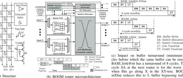
often used for better power efficiency [27]. The key com-ponents of such a crossbar are the input drivers, wires (horizontal and vertical), and the crosspoint switches, as highlighted in Fig. 5(a). Unicasts versus multicasts can offer different design decisions for choosing the switches and drivers. We discuss these next, and show the latency and energy derivations in Table II.
CROSSBAR-A: Pass-gate/Transmission Gate switch. This design is most commonly used due to its simplicity, low-power and low-area. An input driver (like an inverter chain) needs to drive both the horizontal, and vertical wires, while the pass-gates form the appropriate connections at the cross-points. The input drivers are sized to drive one full horizontal and vertical wire. The average energy for a 1-to-1 traversal was observed to be 0.154 pJ/bit in a 5x5 crossbar. However, these crossbars cannot support a broadcast, which requires the input driver to drive one horizontal, and P vertical wires, unless huge slack is available. To support broadcasts, a larger driver would be required, which would show up as a large Cinv−c in the energy equation in Table II, and become an overkill for unicast traffic9.
CROSSBAR-B: Adaptive Input Driver. Since a crossbar is expected to receive a mix of unicasts and multicasts, we propose a variant of CROSSBAR-A with an adaptive input driver. This can be created by using a parallel set of P minimum-sized tri-states, each of which would connect to
9The energy consumption in this case was 0.564 pJ/bit for all traversals,
1-to-1, or 1-to-5
a driver that connects to the input wire. M of the tri-states are turned on when driving M-casts, thereby providing appro-priate current. This design has similar delay characteristics as CROSSBAR-A, but would have lower average power due to the adaptive Cpar−tri. This crossbar consumed an average energy of 0.160 pJ/bit for a 1-to-1 traversal.
Both CROSSBAR-A and CROSSBAR-B however have latencies that increase with M, as highlighted in Table II, which can limit router frequency at high M.
CROSSBAR-C: Tri-state Switch. In this design, the input driver only needs to drive the horizontal wire and can be small. Each vertical wire has its own tri-state driver, and thus this design can support broadcasts. Moreover, the transmission latency of such a crossbar is independent of M as Table II shows, and is thus the fastest and most robust out of all the designs. In terms of energy, the tri-states add extra load on the vertical wires, as highlighted by 2×Cdtriin the equations10. Extracted layouts of transistors, and wires using a 90nm PDK showed that the capacitances of the wires (about 250fJ/mm) are usually an order of magnitude higher than those of the drain/gate/source (about 10fJ). Thus the energy equation for all three designs would be dominated by Cinput−driver, Cwh and Cwv. It thus seems to be the most energy efficient design for supporting multicasts.
However, the caveat is area. The cell-height of the cross-point tri-states is at least 3-times the cell-height of a simple pass-gate11. This could increase the vertical wire length three times, in turn increasing Cwv, and thereby power. The cell-width could be made comparable by allowing the two PMOS devices connected together in the tri-state in Fig. 5(a) to share the drain/source; similarly for the NMOS devices12. As a consequence, modeling this crossbar resulted in an energy of 0.290 pJ/bit/1-to-1 traversal. However, we can
10The tri-state output stage is an inverter, and adds Cd of both the PMOS
and the NMOS
11This is due to the addition of PMOS devices, which are usually sized
to be twice the NMOS size since they are slower
12In reality, however, custom layout designers would not layout this
design exactly as shown in Fig. 5(a), so these simple estimates will not hold completely true
In0-bit 0 In0-bit n In1-bit 0 In1-bit n In2-bit 0 In2-bit n In3-bit0 In3-bit n In4-bit 0 In4-bit n Out0-bit 0 Out0-bit n Out1-bit 0 Out1-bit n Out4-bit 0 Out4-bit n Input Driver Cross-point Switch Out2-bit n Pass Gate in sel out Tri-State in sel out
(a) Matrix Crossbar Structure
Switch Allocator VC Allocator WHIRL Route computation 5x5 Multicast Crossbar switch Input 1 Output 1 Output 5 VC 1 Input buffers VC 2 VC n Input 5 VC 1 Input buffers VC 2 VC n Lookahead Generator Lookahead {outport, LTB,RTB, DestSet Vcid} Lookahead {outport, LTB,RTB, DestSet Vcid} Bypass Path next_outport, next_LTB,RTB LA_LT BW SA ST LT LA_RC LA_SA ST LA_LT LT Time Router n Router n +1 Router Pipelines Flit Lookahead (LA) RC: Route Compute SA: Switch Alloc LT: Link Traversal
(b) BOOM router microarchitecture
BW SA SA SA SA CT LT ST SA 8 cycle roundtrip BW SA CT LT ST SA 5 cycle roundtrip BASE_fork@rtr-XYtree CT LT ST SA BOOM_mXbar BOOM_mXbar_ bypass 3 cycle roundtrip BW: Buffer Write SA: Switch Allocation ST: Switch Traversal LT: Link Traversal CT: Credit Traversal
(c) Impact on buffer turnaround (minimum cy-cles before which the same buffer can be reused). BASE fork@rtr has a turnaround of 8 cycles. The 4 cycle SA at the next router is for the worst case when flits go along X in the XY-tree. BOOM’s mXbar reduces this to 5, buffer bypassing reduces it to 3 cycles.
Fig. 5. BOOM: Broadcast Optimizations for On-chip Meshes
mitigate this issue by avoiding the charging/discharging of the entire vertical wire, by segmenting the crossbar [26]. Thus, input ports close to the output port which wish to broadcast, need not charge the full vertical wire cap Cwv. We modeled the segmented version of this crossbar and observed an average energy of 0.137 pJ/bit/1-to-1 traversal. Segmenting CROSSBAR-A also reduced its energy to 0.099 pJ/bit/traversal (the reduction was not as much as that for CROSSBAR-C due to shorter wires with lower Cwv).
A mXbar like CROSSBAR-C offers an interesting trade-off against the conventional, non-multicast CROSSBAR-A. Clearly, in terms of delay, CROSSBAR-C wins be-cause CROSSBAR-A would require M cycles to transmit M copies of the same flit, while CROSSBAR-C would do it in a cycle. But in terms of total energy for transmis-sion of the M copies, CROSSBAR-A consumes M× 0.099 pJ/bit, while CROSSBAR-C consumes M× 0.137 pJ/bit, which is 38% higher. The Energy-Delay Product indicates that CROSSBAR-C wins by a factor of (1-1.38/M) over CROSSBAR-A. If the average value of M in each router is greater than 1.38, using CROSSBAR-C makes sense from an Energy×Delay perspective. But if unicasts dominate, sticking to the conventional CROSSBAR-A would be more power efficient. We evaluate this proposition further in the evaluation section.
3) Multi-port Switch Allocation: To support the mXbar described above, the switch allocation (SA) needs to grant multiple output ports to the same requesting input port. In addition, VC Allocation (VA) needs to be performed for multiple output ports before the flit is allowed to leave. We enable these as follows:
(1) Requests to, and responses from the switch allocator conform to a 5-bit vector13.
(2) Each input port selects one input VC as the requestor using any arbiter [28].14
(3) All inputs place requests for the switch output ports. Multiple bits can be high in the request to specify multiple requests in case of multicasts.
13Local, West, North, East, South
14A priority arbiter can be used to prioritize VCs which have requests
for the maximum number of output ports.
(4) Bit i, (i=0 to 4) from all requests is sent to an arbiter corresponding to output port i, which selects one input port as the winner, and generates a one-hot encoded response vector.
(5) Each output port maintains a queue corresponding to free VCs at the next router. At the end of SA, a free VC is picked from each output port i, and assigned to the input port that won it [29], thereby performing VA.
(6) The response vectors from (4) setup the mXbar select lines.
(7) Bit j ( j=0 to 4) from all responses from (4) is sent as a bit-vector to input port j. This vector specifies which outport port requests were granted for each input port. Multiple bits can be high, as each output port could have independently picked input port j as the winner. The corresponding flit is sent to the mXbar and forked out.
(8) The buffer corresponding to the flit is made free if all its output port requests were granted, else it re-arbitrates for the remaining ones in the next cycle, thereby supporting partial allocations.
C. Flow Control: Multicast Buffer Bypassing with Looka-heads
1) Background: Buffers in NoC routers are a necessary evil in packet-switched designs. They are required to prevent collisions of flits wishing to use the same output links, but add latency and power [27]. Adding physical express links, such as MECS [30], can help unicast flits to avoid buffers, but multicast flits still need to go via routers to perform forking. Previous works [31], [19], [20] have proposed schemes to speculatively bypass the buffering stage at routers by sending lookahead signals a cycle before the actual data, to pre-allocate the crossbar at intermediate routers. This reduces latency, and also saves buffer read/write power. However, these techniques only work for unicast flits. To the best of our knowledge, no prior art has attempted extending bypassing for multicasts, which is essential for meeting the energy and delay limits of an ideal broadcast network.
2) Single-Cycle Speculative Multicast Buffer Bypassing: Prior works enable bypassing of unicast flits in the following manner: (1) Each flit is preceded by a lookahead that reaches the next router a cycle in advance. It carries the output port
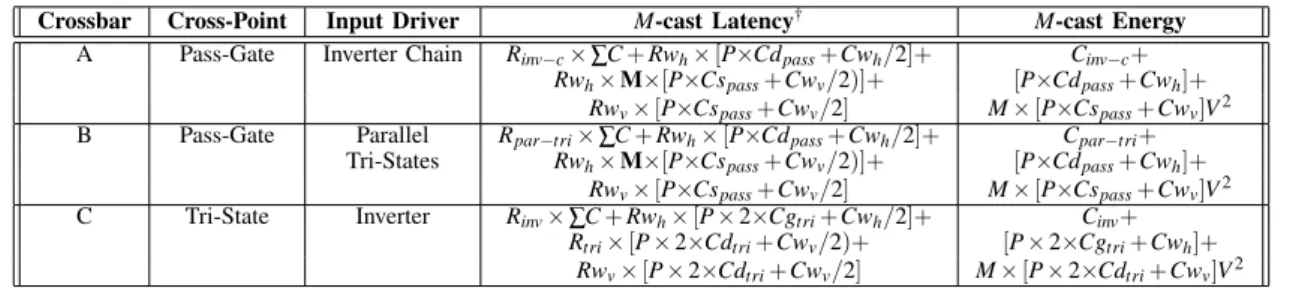
TABLE II
Latency and Energy comparison for PxP matrix crossbars designs that support multicast
Crossbar Cross-Point Input Driver M-cast Latency† M-cast Energy
A Pass-Gate Inverter Chain Rinv−c× ∑C + Rwh× [P×Cdpass+Cwh/2]+ Cinv−c+
Rwh× M×[P×Cspass+Cwv/2)]+ [P×Cdpass+Cwh]+
Rwv× [P×Cspass+Cwv/2] M× [P×Cspass+Cwv]V2
B Pass-Gate Parallel Rpar−tri× ∑C + Rwh× [P×Cdpass+Cwh/2]+ Cpar−tri+
Tri-States Rwh× M×[P×Cspass+Cwv/2)]+ [P×Cdpass+Cwh]+
Rwv× [P×Cspass+Cwv/2] M× [P×Cspass+Cwv]V2
C Tri-State Inverter Rinv× ∑C + Rwh× [P × 2×Cgtri+Cwh/2]+ Cinv+
Rtri× [P × 2×Cdtri+Cwv/2)+ [P × 2×Cgtri+Cwh]+
Rwv× [P × 2×Cdtri+Cwv/2] M× [P × 2×Cdtri+Cwv]V2
† First-order RC time constant is estimated using the Elmore Delay Model for distributed RC segments.
P: number of ports, Cd/Cg/Cs : Drain/Gate/Source Capacitances of devices,
Rwh/Rwv: Horizontal/Vertical Wire Resistance, Cwh/Cwv: Horizontal/Vertical Wire Capacitance.
request, and arbitrates for the crossbar, while the flit traverses the link. (2) Successful arbitration sets up a demux that allows the flit to connect directly to the crossbar and proceed out of its output port, instead of going to the buffers. (3) A new lookahead is generated and sent along further along the flit’s path.
We discuss the issues and our solutions for each of these three steps that can enable a multicast router to support speculative bypassing. The lookaheads need to carry more information to support simultaneous buffer bypassing and forking, which potentially continues at all routers till the flit reaches its destination. For unicasts, lookaheads carry the VCid, one output port request, and the destination id [19], [20]. For multicasts, they need to carry the VCid, multiple output port requests, and the destination set. In addition, to support WHIRL, the LTB and RTB bits need to be in the lookahead. However, these information are no longer needed in the flit, so lookaheads are not strictly an overhead.
With these lookaheads, BOOM enables speculative by-passing as follows. It uses the same 5-bit vector which was described previously in Section III-B.3 with multiple bits high to efficiently encode multiple output port requests required for (1). For (2), the mXbar is necessary. Otherwise the flit will be forced to get buffered at all routers where it is getting forked, to serially send out all copies. The lookahead arbitration for the crossbar works similar to the switch allocator described in Section III-B.3. The incoming lookahead’s output port requests are in the same 5-bit format described before, and are prioritized over the requests of other flits buffered at that input port. They are sent to the switch allocator, which breaks conflicts. If the lookahead wins all of its ports, the incoming flit does not need to get buffered, and forks out using the mXbar. BOOM also allows partially successful allocations by the lookahead, in which case the incoming flit simultaneously uses the bypass path to connect to the mXbar, and also gets buffered.
To support (3), BOOM generates multiple lookaheads, one corresponding to each output port out of which the flit forks. The WHIRL bits and the destination set from the incoming lookahead fans out to three15 WHIRL blocks, similar to
Fig. 3(a). Each vector that is generated is embedded into the outgoing lookahead for that output port, which is sent out upon successful switch allocation. The actual flit meanwhile traverses the mXbar.
15For a five-port router, assuming no u-turns, the flit can fork out of
4-ports at maximum. No routing is required for the NIC port.
D. Achieving ideal energy-delay-throughput using BOOM The load-balanced network routing with WHIRL, com-bined with the ability to fork out of routers in a single-cycle using the mXbar, enhanced with the ability to bypass buffering despite forks, together form the BOOM microar-chitecture, which is shown in Fig. 5(b), with each of these additions to a baseline router shaded in gray. The pipelines followed by the lookahead and the flit are also shown. In a BOOM network, a broadcast/multicast propagates as follows: (1) The source NIC calculates the WHIRL route, then embeds that into a lookahead as four sets of LTB and RTB bits (Section III-A), along with the output port requests and the destination set, and sends it out to its router.
(2) This incoming lookahead performs route-computation for all neighbors based on the LTB and RTB bits (Section III-A), and in parallel performs switch allocation (as described in Section III-B.3) where it competes for the mXbar along with lookaheads from other ports, and buffered flits. (3) Based on the success of the lookahead, the incoming flit gets buffered, and/or bypasses directly to the crossbar and forks (as described in Section III-C.2).
(4) Lookaheads are generated and sent out to all the neigh-boring routers while the flit traverses the mXbar (as described in Section III-C.2).
(5) Steps (2)-(4) are repeated at each router until all desti-nations are reached.
In the best case, a BOOM broadcast/multicast can be delivered to all destination NICs without any intermediate buffering at routers, incurring only wire delay and energy (crossbar and links). This enables the ideal energy-delay for broadcasts derived in Table I. With WHIRL balancing broad-cast/multicast traffic evenly across all mesh links, and mXbar plus multicast bypassing enabling single-cycle router traver-sals and minimal buffer turnaround time, broadcast/multicast throughput can be maximized with very few buffers.
IV. EVALUATIONRESULTS
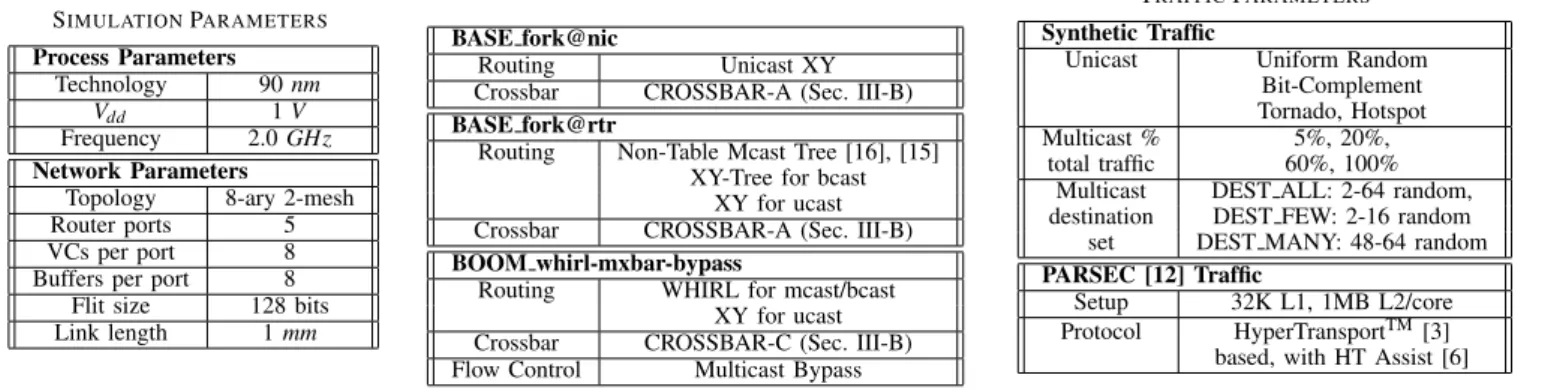
We modeled BOOM and the baseline network designs in detail, within the cycle-accurate network simulator Gar-net [32], and used ORION 2.0 [25] to determine the Gar-network energy consumption, with new models for the different cross-bar circuits. Table III describes our simulation parameters. Table IV describes our baseline routers BASE fork@nic and BASE fork@rtr. Table V summarizes the traffic patterns we use.
TABLE III SIMULATIONPARAMETERS Process Parameters Technology 90 nm Vdd 1 V Frequency 2.0 GHz Network Parameters
Topology 8-ary 2-mesh
Router ports 5
VCs per port 8
Buffers per port 8
Flit size 128 bits
Link length 1 mm
TABLE IV ROUTERPARAMETERS
BASE fork@nic
Routing Unicast XY
Crossbar CROSSBAR-A (Sec. III-B)
BASE fork@rtr
Routing Non-Table Mcast Tree [16], [15] XY-Tree for bcast
XY for ucast
Crossbar CROSSBAR-A (Sec. III-B)
BOOM whirl-mxbar-bypass
Routing WHIRL for mcast/bcast
XY for ucast
Crossbar CROSSBAR-C (Sec. III-B)
Flow Control Multicast Bypass
TABLE V TRAFFICPARAMETERS
Synthetic Traffic
Unicast Uniform Random
Bit-Complement Tornado, Hotspot
Multicast % 5%, 20%,
total traffic 60%, 100%
Multicast DEST ALL: 2-64 random, destination DEST FEW: 2-16 random
set DEST MANY: 48-64 random
PARSEC [12] Traffic
Setup 32K L1, 1MB L2/core
Protocol HyperTransportTM[3]
based, with HT Assist [6]
A. Network-only Simulation
1) Limit Study with Broadcast Traffic: We start by study-ing BOOM in the presence of only broadcasts, and char-acterize it against the ideal broadcast mesh metrics derived in Section II. We inject a synthetic broadcast traffic pattern where uniformly-random sources inject single-flit broadcast packets into the network, at a specified injection rate. The metric we use for evaluation of latency is broadcast latency which we define to be the latency between generation of a broadcast packet at a network interface, to the receipt of the tail flit of the last copy at the destination network interfaces. Saturation throughput is the injection rate at which the average latency reaches 3-times the low-load latency.
Latency and Throughput. Fig. 6(a) shows the
aver-age broadcast latency as a function of injection rate for BOOM whirl-mxbar-bypass, compared to the two baselines. The IDEAL lines are calculated from Table I by setting k=8, and link delays T r(r/n)=1. We observe that BOOM whirl-mxbar-bypass has 60.6% lower low-load latency, and 62.7% higher throughput than BASE fork@rtr; and 86.4% low-load latency, and 380% higher throughput than BASE fork@nic NoC. WHIRL by itself results in 22.2% improvement in throughput, bypassing by itself results in 37.0% reduction in low-load latency, and 22.2% improvement in throughput, and the mXbar by itself results in a 24.2% lower low-load latency, and 62.7% higher throughput. These are not shown in Fig. 6(a) for clarity, but will be explored in detail later.
Energy. Near saturation, BOOM results in an
en-ergy reduction of 70.9% over BASE fork@nic due to non-replication of flits. The energy savings over the BASE fork@rtr are 80.1% in buffer read/write energy (for 8 buffers per port in both networks), and 11.6% overall.
We also ran BOOM with 4 buffers per port (Fig. 6(b)), and observed that it achieves similar throughput as the BASE fork@rtr with 8 buffers per port, reiterating Fig. 5(c). With this configuration, BOOM shows a 68.4% and 31.2% reduction in dynamic and leakage16 energy of buffers,
re-spectively; leading to an overall reduction of 10.7% and 6.7% in dynamic and leakage energy of the network, respectively. In summary, with worst case traffic (100% broadcasts), BOOM’s latency is 5% off ideal on average prior to network saturation, attains 96% throughput of the ideal, with energy consumption just 9% above ideal.
16Having fewer buffers in the network lowers leakage energy compared
to the baseline
2) BOOM for mixed unicast-multicast traffic: We evaluate the impact of BOOM with multicast traffic in the presence of various kinds of unicast traffic (uniform random, tor-nado, bit-complement and hot-spot). We discuss the results for a network with 20% multicast traffic with number of destinations varying randomly from 2-64 at each injection (DEST ALL from Table V). For uniform-random (Fig. 6(c)), WHIRL helps improve throughput by 17.5%, mXbar re-duces low-load latency by 18% and improves throughput by 26.3%, while multicast bypassing reduces low-load latency by 31.4%. Combining all three techniques results in a low-load latency reduction of 49% and throughput improvement of 43.7%. A similar trend is observed in bit-complement (Fig. 6(d)). In tornado (Fig. 6(e)), however, mXbar improves throughput by 30.7%, but adding WHIRL and multicast bypassing to it do not improve throughput further like in uniform-random and bit-complement. This is because tor-nado traffic has unicast flits traveling continuously only on the X links. Thus load-balancing by WHIRL ultimately gets limited by the highly imbalanced unicast traffic. An extreme case of this phenomenon is observed in Hot-Spot traffic17 (Fig. 6(f)). BOOM enables 49% lower low-load latency, but is not able to push throughput by greater than 15% since the highly contended and imbalanced Y-links near the hot-spot nodes limit network saturation (since unicast traffic uses XY routing).
In summary, WHIRL and mXbar help improve throughput, while mXbar and multicast bypassing help lower the latency, as highlighted in Fig. 6. Since BOOM enables each technique to gel with the other, combining them results in up to 49% reduction in latency, and 44% higher throughput, due to efficient and faster use of links, unless adversarial unicast traffic limits the overall network.
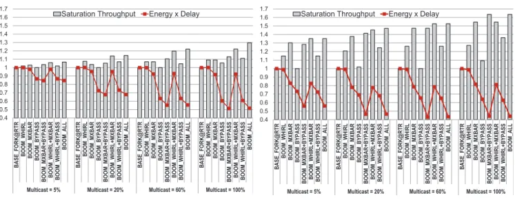
3) Breakdown of impact of WHIRL, mXbar and bypass: Next we evaluate the impact of each component of BOOM on performance and power as a function of the amount of multicast traffic in the network, and the size of the desti-nation sets. Fig. 7 plots the network saturation-throughput, and the Energy-Delay Product (EDP) at low-loads, for two kinds of destination sets: DEST MANY (48-64 destina-tions randomly chosen) and DEST FEW (2-16 destinadestina-tions randomly chosen), and sweeps through the percentage of multicasts in the network. The unicast traffic is
uniform-17We selected four hot-spot nodes in the network, and all unicast traffic
BASE_fork@nic BASE_fork@rtr
250
cy
BOOM_whirl mXbar bypass IDEAL
200 250 t La te n 150 ad ca st 50 100 ge B ro a 0 50 A ve ra g 0 0.1 0.2 0.3 0.4 0.5 0.6 0.7 0.8 0.9 1 1.1 Injection Rate (fraction of capacity)
(a) Random Broadcast Traffic
BASE_fork@rtr_8buf BOOM_8buf BOOM_4buf
250 cy 200 t La te n 150 ad ca st 50 100 ge B ro a 0 50 A ve ra g 0 0.1 0.2 0.3 0.4 0.5 0.6 0.7 0.8 0.9 1 Injection Rate (fraction of capacity)
(b) BOOM with fewer buffers
0 10 20 30 40 50 60 70 80 90 0 0.02 0.04 0.06 0.08 0.1 0.12 0.14 A ve ra ge f lit l at en cy ( cy cl es )
Injection Rate (flits/cycle/node) BASE_fork@rtr BOOM_whirl
BOOM_bypass BOOM_mXbar
BOOM_whirl mXbar bypass
(c) Uniform Random Unicast BASE_fork@rtr BOOM_whirl
BOOM_bypass BOOM_mXbar
90
s)
BOOM_whirl mXbar bypass
60 70 80 (c yc le s 40 50 60 at en cy 20 30 40 e fli t l a 0 10 20 A ve ra ge 0 0.02 0.04 0.06 0.08 0.1 0.12 0.14 A
Injection Rate (flits/cycle/node)
(d) Bit-Complement Unicast
BASE_fork@rtr BOOM_whirl BOOM bypass BOOM mXbar
90
)
BOOM_bypass BOOM_mXbar BOOM_whirl mXbar bypass
70 80 (c yc le s 40 50 60 te nc y ( 20 30 40 e fli t l at 0 10 20 ver ag e 0 0.02 0.04 0.06 0.08 0.1 0.12 0.14 A v
Injection Rate (flits/cycle/node)
(e) Tornado Unicast
BASE_fork@rtr BOOM_whirl BOOM bypass BOOM mXbar
90
)
BOOM_bypass BOOM_mXbar BOOM_whirl mXbar bypass
70 80 cy cle s) 40 50 60 te nc y ( 20 30 40 fli t l at 0 10 20 ver ag e 0 0.02 0.04 0.06 A v
Injection Rate (flits/cycle/node)
(f) Hot-Spot Unicast Fig. 6. Performance with 100% broadcasts (a, b), and 80% unicasts + 20% DEST ALL multicasts (c-f).
0.4 0.5 0.6 0.7 0.8 0.9 1 1.1 1.2 1.3 1.4 1.5 1.6 1.7 B A S E _FO R K @ R T R B O O M _ WH IR L B O O M _ M X B A R B O O M _ B Y P A S S B O O M _ M X B A R + B Y P A S S B O O M _ WH IR L + M X B A R B O O M _ WH IR L+ B Y P A S S B O O M _ A L L B A S E _FO R K @ R T R B O O M _ WH IR L B O O M _ M X B A R B O O M _ B Y P A S S B O O M _ M X B A R + B Y P A S S B O O M _ WH IR L + M X B A R B O O M _ WH IR L+ B Y P A S S B O O M _ A L L B A S E _FO R K @ R T R B O O M _ WH IR L B O O M _ M X B A R B O O M _ B Y P A S S B O O M _ M X B A R + B Y P A S S B O O M _ WH IR L + M X B A R B O O M _ WH IR L+ B Y P A S S B O O M _ A L L B A S E _FO R K @ R T R B O O M _ WH IR L B O O M _ M X B A R B O O M _ B Y P A S S B O O M _ M X B A R + B Y P A S S B O O M _ WH IR L + M X B A R B O O M _ WH IR L+ B Y P A S S B O O M _ A L L
Multicast = 5% Multicast = 20% Multicast = 60% Multicast = 100%
Saturation Throughput Energy x Delay
(a) DEST FEW (2-16) Multicasts + Uniform Random Unicast
0.4 0.5 0.6 0.7 0.8 0.9 1 1.1 1.2 1.3 1.4 1.5 1.6 1.7 B A S E _FO R K @ R T R B O O M _ WH IR L B O O M _ M X B A R B O O M _ B Y P A S S B O O M _ M X B A R + B Y P A S S B O O M _ WH IR L+ M X B A R B O O M _ WH IR L+ B Y P A S S B O O M _ A L L B A S E _FO R K @ R T R B O O M _ WH IR L B O O M _ M X B A R B O O M _ B Y P A S S B O O M _ M X B A R + B Y P A S S B O O M _ WH IR L+ M X B A R B O O M _ WH IR L+ B Y P A S S B O O M _ A L L B A S E _FO R K @ R T R B O O M _ WH IR L B O O M _ M X B A R B O O M _ B Y P A S S B O O M _ M X B A R + B Y P A S S B O O M _ WH IR L+ M X B A R B O O M _ WH IR L+ B Y P A S S B O O M _ A L L B A S E _FO R K @ R T R B O O M _ WH IR L B O O M _ M X B A R B O O M _ B Y P A S S B O O M _ M X B A R + B Y P A S S B O O M _ WH IR L+ M X B A R B O O M _ WH IR L+ B Y P A S S B O O M _ A L L
Multicast = 5% Multicast = 20% Multicast = 60% Multicast = 100%
Saturation Throughput Energy x Delay
(b) DEST MANY (48-64) Multicasts + Uniform Random Unicast Fig. 7. Normalized Saturation Throughput and Energy-Delay-Products for BOOM’s components.
random in all cases. We demonstrate the impact of each com-ponent of BOOM based on these results. BOOM WHIRL refers to the BASE fork@rtr network with WHIRL routing. BOOM mXbar refers to the BASE fork@rtr network with a multicast crossbar, but using the baseline multicast tree, and so on. BOOM ALL has all three techniques. We can see that in both traffic conditions, there is a consistent reduction in EDP due to BOOM. For DEST MANY, for which BOOM is primarily intended, BOOM’s components lead to 40-60% higher network throughput, and upto 56% lower EDP.
WHIRL. For DEST FEW, with 5% multicasts, WHIRL’s
performance is very comparable to BASE fork@rtr. This is expected because for such a configuration, both WHIRL and BASE fork@rtr create routes that match the destination locations. WHIRL wins slightly because conflicts are broken by random LTB/RTB choices in WHIRL, as was shown in Fig. 2(e), while BASE fork@rtr uses fixed priorities. WHIRL starts improving throughput as the percentage of multicasts increase. The real benefits of WHIRL can be seen
in the DEST MANY where it gives 18-25% improvement by itself, and upto 60% in conjunction with BOOM’s other optimizations.
WHIRL’s EDP is similar to the fork@rtr, because at low-loads, at which the EDP was calculated, both WHIRL and fork@rtr traverse similar routes, incurring similar number of buffer writes/reads and crossbar/link traversals.
mXbar. For DEST FEW, the mXbar does not show a
huge benefit, and offers throughput improvements similar to WHIRL. The reason is that the percentage of unicast dominate over multicasts, so the mXbar does not have much work to do in terms of forking flits. As the percentage of multicasts increase, WHIRL+mXbar push the throughput by 20-30%, and lower EDP by 35-50%. For DEST MANY, however, mXbar steals the show completely. In almost all cases, it single-handedly pushes the throughput to within 10% of the maximum achieved by all three techniques together. However, as discussed earlier in Section III-B, the mXbar has higher energy/bit/1-to-1 traversal, and was found
to consume higher power than the baseline. But the reduction in latency due to mXbar offsets that and leads to 17-22% lower EDP than the baseline.
Multicast Buffer Bypassing. Multicast bypassing does
not offer any significant throughput improvement by itself, in both DEST FEW and DEST MANY. This might seem contradictory to all previous works on unicast buffer by-passing [19], [20]. The reason for this is that byby-passing helps increase throughput by enabling faster turnaround of buffer usage. For multicasts however, the buffer cannot be freed until all copies of the flit leave! Buffers can only be bypassed at routers which are not forking flits along the multicast route. But multicast bypassing by itself does have delay benefits, because it enables flits to proceed to the crossbar as soon as they enters, while a copy is also retained at the buffers. This enables a 20-40% reduction in EDP even in the DEST FEW case. When multicast bypassing is combined with WHIRL, or mXbar, more of its benefits come to light. With WHIRL enabling more load balanced routing, the chances of bypassing routers outside of the destination set increases due to lower contention. With mXbar, the biggest benefit of bypassing is in terms of energy. mXbar coupled with bypassing enables huge savings in buffer read/write energy. It also allows faster recycling of buffers, and better link utilization, all of which push throughput by up to 60% in some cases.
In summary, for networks with few multicasts, and small destination sets, WHIRL and mXbar provide similar perfor-mance improvements. Since WHIRL adds minimum over-head to the router, it would be a better solution than re-designing the crossbar to support multicasts. For dense mul-ticasts/broadcasts, however, the mXbar is critical for good performance. In this case, latency and power can be saved further by adding multicast bypassing.
B. BOOM with Real Applications
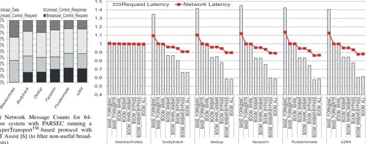
We evaluate the impact of BOOM on real multi-threaded applications by using network traces of 64-thread PARSEC benchmarks [12] running on the M5 [33] infrastructure, using the X86 CPU model and the GEMS [34] memory model. Table V lists our setup.
Fig. 8(a) shows that in our setup, for all benchmarks, ex-cept for blackscholes, 38-50% of all requests are broadcasts. This leads to an overall 16-23% broadcast traffic across the control and data messages18. blackscholes was found to fit its entire data set in its local cache, and thus did not result in many misses.
We measured the average network latency of packets on the request network (Fig. 8(b)) as BOOM optimizes just broadcasts and multicasts, which are only leveraged for requests here. All results are normalized to BASE fork@rtr which is our baseline multicast router. We also show BASE fork@nic for completeness. blackscholes is an outlier
18The control packets are all one-flit wide, while the data packets
are 5-flit wide. Garnet [32] models separate virtual networks for Uni-cast Control Request, UniUni-cast Control Response, and UniUni-cast Data packets. The Broadcast Control Request packets share the virtual network with the Unicast Control Request packets. We gave 8 VCs to each virtual network. The control VCs were each one-buffer deep, while the data VCs were each 3-buffers deep.
and does not show any significant speedup since it has less than 1% broadcasts, and will be excluded from further discussions. For all other benchmarks, BASE fork@nic is completely saturated due to serialization of 64 separate packets through the NIC injection port, and thus upto 45% slower than BASE fork@rtr. This reiterates the need to have multicast network support. BOOM WHIRL does not show much improvement in latency here because the network is operating at a fairly low injection rate and so the baseline XY broadcast tree is good enough here. BOOM mXbar results in 14-16% latency reduction. BOOM bypass itself results in 20-25% speedup across all benchmarks. Combined with the mXbar, it helps lower latency by a further 15%. Overall, BOOM enables 34-41% speedup in request messages across all benchmarks.
Fig. 8(b) also overlays the overall network latency. BOOM lowers network latency by about 10% in bodytrack and dedup, and about 15% in fluidanimate and x264. Higher savings in the latter two occur because they have about 6-8% more broadcasts than the former two. A lot of the network latency is also dominated by the data packets, since the 13-20% data packets in these benchmarks each give rise to 5-flits.
It should also be noted that in these PARSEC traces, each broadcast/multicast request invalidate message would result in many unicast acknowledgement messages from the destinations, all fanning back to the originator of the broad-cast. These fall under Unicast Control Response in Fig. 8(a). While BOOM effectively optimizes 1-to-M multicasts, it does not address the reverse M-to-1 aggregation. Tackling this reverse flow should lead to further improvements in overall network performance and is an interesting problem for future research.
V. CONCLUSIONS
We proposed Broadcast Optimizations to On-chip Meshes (BOOM) to enable a mesh to approach ideal energy-delay-throughput for broadcasts. In particular, we introduce the WHIRL routing algorithm, a multicast crossbar circuit, and bypass flow-control for multicasts, which successfully achieves near-ideal energy-delay-throughput.
REFERENCES
[1] J. Laudon and D. Lenoski, “The sgi origin: a ccnuma highly scalable server,” in ISCA ’97: Proceedings of the 24th annual international
symposium on Computer architecture. New York, NY, USA: ACM, 1997, pp. 241–251.
[2] D. Lenoski, J. Laudon, K. Gharachorloo, A. Gupta, and J. Hennessy, “The directory-based cache coherence protocol for the dash multipro-cessor,” in ISCA. New York, NY, USA: ACM, 1990, pp. 148–159. [3] A. Ahmed, P. Conway, B. Hughes, and F. Weber, “AMD Opteron
shared memory MP systems,” in 14th Hot Chips Symposium, August 2002.
[4] N. Agarwal, L.-S. Peh, and N. K. Jha, “In-network snoop ordering (INSO): Snoopy coherence on unordered interconnects,” in HPCA, Feb. 2009.
[5] M. M. K. Martin, M. D. Hill, and D. A. Wood, “Token coherence: Decoupling performance and correctness,” in Proceedings of
Interna-tional Symposium on Computer Architecture, Jun. 2003.
[6] P. Conway, N. Kalyanasundharam, G. Donley, K. Lepak, and B. Hughes, “Cache hierarchy and memory subsystem of the AMD Opteron processor,” IEEE Micro, vol. 30, pp. 16–29, 2010. [7] M. M. K. Martin, D. J. Sorin, M. D. Hill, and D. A. Wood,
“Bandwidth adaptive snooping,” in HPCA. Washington, DC, USA: IEEE Computer Society, 2002, p. 251.
![Fig. 1. Baseline Broadcast Networks (fork@nic, fork@rtr (modeled similar to VCTM [13], MRR [14], bLBDR [15] and RPM [16]) with tree-based route and logical ring route) vs](https://thumb-eu.123doks.com/thumbv2/123doknet/14179667.476015/3.892.92.828.79.296/baseline-broadcast-networks-modeled-similar-vctm-blbdr-logical.webp)