Distributed & Conceptual CAD (DC-CAD):
A New Software Solution for Product Design
byMark D. Egan
SUBMITTED TO THE DEPARTMENT OF MECHANICAL ENGINEERING IN PARTIAL FULFILLMENT OF THE REQUIREMENTS FOR THE DEGREE OF
BACHELOR OF SCIENCE AT THE
MASSACHUSETTS INSTITUTE OF TECHNOLOGY
JUNE 2007
©2007 Mark Egan. All rights reserved.
The author hereby grants to MIT permission to reproduce and to distribute publicly paper and electronic copies of this thesis document in whole or in part
in any medium now known or hereafter created.
Signature of Author:
Department of Mechanical Engineering
5/11/07
Certified by:
David C. Cossard r osseforP of Mechanical En ineerin
Thesis Supervisorhesis Supervisor
Accepted by:
John H. Lienhard V Professor of Mechanical Engineering Chairman, Undergraduate Thesis Committee
MASSACHUSETTS INSTITUTE
OF TECHNOLOGY
JUN
2
1
2007
LIBRARIES
Distributed & Conceptual CAD (DC-CAD):
A New Software Solution for Product Design
by
Mark D. Egan
Submitted to the Department of Mechanical Engineering on May 1 1t, 2007 in Partial Fulfillment of the
Requirements for the Degree of Bachelor of Science in Engineering As Recommended by the Mechanical Engineering Department
ABSTRACT
Many computer aided design (CAD) software packages focus on detailed design and not on early stage, conceptual design. The ability to conceptualize and sketch early versions of a product solution is currently limited to paper and pencil or to inadequate computer-aided industrial design programs (CAID) that focus mainly on surface design, not product design. Working on a design as a group also poses problems since the team can be geographically distributed. In an attempt to address the current inadequacies of CAD systems for distributed conceptual design, my thesis proposes a vision for a new CAD program, DC-CAD. This vision anticipates network-orientated conceptual design, and encompasses capabilities for multiple users to collaborate simultaneously on design, compare & evaluate concept sketches, comment on designs and merge changes from other designers, transfer data to detailed design CAD programs, and record concept changes over time. MIT's Product Engineering Class (2.009) was used as the basis for conceiving the software system. By analyzing design challenges that arose during the course, new software features are suggested to mitigate such problems. The end result is a clear vision for a new program, DC-CAD, and a storyboard example of how it could be used in a futuristic 2.009 setting. The thesis closes with recommendations on how to
pursue the implementation and realization of such a CAD system.
Thesis Advisor: David C. Gossard
Biographical Note
Mark Douglas Egan was born in Toronto, Canada, in 1985 and entered the Massachusetts Institute of Technology as an undergraduate in August 2003, slated to graduate on June 8th, 2007, with a Bachelor's of Science in Engineering as Recommended by the
Mechanical Engineering Department. A student in Course 2A, his concentration was in Course 15 (Management Science), specializing in IT Management & Systems
Engineering. He also graduated with a minor in Course 17 (Political Science). His senior year he was co-captain of the MIT Men's Varsity Tennis Team (having played all four years while at MIT), and was a member in the American Jiu-Jitsu Club for two years, attaining the level of Yellow Belt. He was also inducted into the National Society
Contents
1. Background & Problem . . . 8
1.1. The Product Design Process . . . 8
1.2. Conceptual Design . . . 9
1.3. Problem . . . 10
2. Importance 12 3. Literature Review 14 3.1. CAD, CAID, & Conceptual Design Technology Efforts 14 3.2. Distributed/Collaborative Computing & Design 15 3.3. Literature Impact . 17 4. Research & Methods . 19 4.1. Current Product Analysis . . 19
4.2. 2.009 Design Experience 21 4.3. The 'DC-CAD' Vision . . 24
4.3.1. Distributed Design . . . 24
4.3.2. Conceptual Design . 25
4.3.3. Communication 25
4.3.4. Life Cycle Design Continuity 26
4.4. A 'DC-CAD' Storyboard - A Hypothetical DC-CAD Example 28
5. Lessons Learned & Significance . 32
6. Recommendations 33
List of Figures
1-1 Design Process Flow Diagram
3-1 ROCCAD Screenshot
4-1 DC-CAD Feature Set
4-2 DC-CAD Hypothetical Screenshot 4-3 DC-CAD Storyboard
List of Tables
4.1 Current CAD System Comparison 4.2 2.009 Design Process Challenges
Chapter 1
Background & Problem
1.1 The Product Design Process
Product design is a multi-step process, including idea generation, prototyping, testing, cyclic revisions, and final design manufacturing. Once a development team has chosen an idea, prototyping of the model is performed with standard Computer-Aided Design
(CAD) packages, such as Solidworks or ProEngineer. However, prototyping and its design stage, 'detailed design', are preceded by a crucial phase known as conceptual design. While some research has proposed metrics for feature based conceptual design programs, no effective software solutions exist that embody the three metrics of: 1) effective conceptual design management, 2) integration into detailed design applications, and most importantly, 3) collaboration from multiple, geographically dispersed
designers.' It is important to understand that decisions made during conceptual design have a disproportionate influence on the outcome of a project. This exposes a problem: if conceptual design has such a large influence yet no software package exists to aid
designers, decisions are made with insufficient knowledge.
1 Brunetti G.; Golob B. "A feature-based approach towards an integrated product model including conceptual design information". Computer-Aided Design, Volume 32, Number 14, December 2000, pp.
1.2 Conceptual Design
Since this thesis focuses on the lack of tools for conceptual design, one must grasp the
fundamental difference between conceptual and detailed design. Figure 1-1 is a diagram
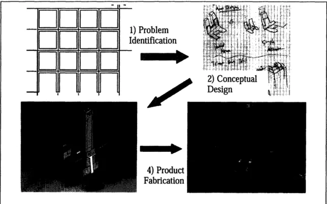
representing the unidirectional flow between four main areas of the design process: 1) Problem Identification, 2) Conceptual Design, 3) Detailed Design, and 4) Product Fabrication.
Figure 1-1: A flow diagram summarizing the design process in four steps: Problem Identification, Conceptual Design, Detailed Design, and Product Fabrication; few software programs allow effective conceptual design, and no programs enable file feeds to detailed design programs nor allow multiple users to simultaneously modify the same file
As evident in Figure 1-1, the design process involves multiple steps, but as can be seen,
the idea progresses from paper-and-pencil ideas (in stage 2) to a very detailed CAD
model (in stage 3). In the identification phase, little software guidance is needed to
progress effectively, yet in both stage three and four software solutions are extensively
E
D
E E
1) Problem IdentificationH HI
4)
Product
Fabrication
a
n
n
F1
0
N
N
c • E Wused. For detailed design, CAD programs are used, and for product fabrication, Computer-Aided Manufacturing (CAM) packages are used. Programs such as Solidworks serve little purpose during conceptual design, and can even serve to limit ideas if used during the conceptual design process; a more useful tool would be a pad of paper and a pencil, or better yet a novel software program tailored specifically for conceptual design.2 Thus the solution must be able to bridge the gap between the ideas
phase and the detailed design phase. A line of software tools does exist embracing some of this conceptual functionality, labeled as computer-aided industrial design (CAID) programs. However, careful analysis of these systems shows key functions missing that will serve the basis for candidate functionality of a new design system specifically for collaborative, conceptual design.
1.3 Problem
A deficiency in electronic design tools at the conceptual design stage creates a problem
for engineers, because decisions made during conceptual design have a disproportionate impact on end product results. Since no effective system exists to effectively model and evaluate critical conceptual designs, important decisions are therefore made with
insufficient knowledge. Studies have shown these decisions at the conceptual design phase can contribute to seventy-five percent of the final product cost.3
2 Guidera, Dr. Stan G. "Assessing the use of digital sketching and conceptual design software in
first-year architectural design studio." Proceedings of the 2004 American Society for Engineering
Education Annual Conference & Exposition., Copyright © 2004, American Society for Engineering
Education
3 Hsu, W. & B. Liu., "Conceptual design: issues and challenges." Computer Aided Design. Volume 32. (2000) pp. 849-850
Most electronic design tools on the market focus on detailed design. And although some of these new (CAID) systems exhibit some conceptual design
functionality, such as freeform surface modeling, concept sketching capabilities, and connection downstream into detailed design formats, none of the packages enable the user to make incomplete geometries and fully conceptual solid models. Further still, none allow the collaboration from multiple, simultaneous designers. The ability to work as a team from geographically dispersed (distributed) areas would drastically help reduce product development time; collaborative design research has emerged parallel to the necessary advances in information technology (IT) to facilitate this function.4 Lastly, no
current CAD systems feature any form of version control or record keeping essential for early design reviews. In sum, there exists a veritable dearth of effective systems
necessary to undertake significant conceptual design in an electronic and collaborative setting.
Chapter 2
Importance
In seeking an effective solution that would help teams better coordinate conceptual design efforts, efficiency to develop novel products would improve and could help reduce downstream design costs. As noted before, conceptual design choices can contribute up
to seventy-five percent of the final product cost.5 Additional changes further along in the
design process past the conceptual stage become costly to fix.
The objective of this thesis is to articulate a vision for candidate functionality in order to address the holes in current CAD & design technology with regard to utility for distributed, conceptual design. First, I examine relevant past research in the areas of CAD, CAID, Conceptual Design Technology, and the distributed & collaborative computing & design environments. Next, I examine the current status of leading CAD and CAID systems now in use by designers for both conceptual and detailed design. I then examine a case study of the MIT senior design class, The Product Engineering Process (2.009), and how certain design challenges could have been mitigated by specific software features not currently available in existing systems. By exposing the
deficiencies of current systems and using 2.009 as a backdrop for proposed features, I then outline the vision of a new system, DC-CAD, with ideal functionality for such a distributed, conceptual system. I then create a hypothetical example to examine how DC-5
CAD could be used in a similar 2.009 experience to better serve product designers. I also
examine the lessons learned in reaching this proposed new functionality, as well as the significance such a system might have. Lastly, I put forth my recommendations for moving forward with the system and the next steps needed to actually create the program, DC-CAD.
Chapter 3
Literature Review
Current computer-aided design systems and research into conceptual design programs fail to address many challenges during the design process. First, effective conceptual design is difficult to achieve with current CAD software.6,7 Second, integration of conceptual
designs with detailed design programs has been overlooked in current CAD research.8
Third, collaboration between numerous individuals from distributed locations has been studied, but with minimal practical application.
3.1 CAD, CAID, & Conceptual Design Technology Efforts
Few CAD systems today address conceptual design needs.9 While research has been done into specific methods for rendering and surface creation for incomplete geometries, little research has focused on the higher-level features such a program must embody to be useful to designers.'0,'1 Several papers broach specific algorithms for transferring
sketches to 3D models; however, the approaches are both very industry and case
6 van Elsas P.A.; Vergeest J.S.M. "New functionality for computer-aided conceptual design: the
displacement feature". Design Studies, Volume 19, Number 1, January 1998, pp. 81-102(22) Brunetti G.; Golob B. ibid.
8Brunetti G.; Golob B. ibid.
9 Brunetti G.; Golob B., ibid.
0o Van Dijk, C.G.C. "New insights in computer-aided conceptual design". Design Studies, Volume 16, Number 1, January 1995, pp. 62-80(19)
n van Elsas P.A.; Vergeest J.S.M. "Displacement feature modelling for conceptual design". Computer-Aided Design, Volume 30, Number 1, January 1998, pp. 19-27(9)
specific.'",'" Another paper underlines the absolute necessity of CAD systems to include effective sketch capabilities, a feature the paper claims has been underdeveloped.'4 Other
papers focus on special surface algorithms for flexible, conceptual surface design unlike the rigidity required by detailed design systems.'5 However, this offers little practical
applicability for conceptual product design. The last two important papers explore the utility of using alternative interface capabilities, specifically virtual reality environments, for inputting to conceptual design systems.'6," This too serves little applicability to the goal of this thesis in developing a standard interface conceptual design program.
3.2 Distributed/Collaborative Computing & Design
Research in the area of collaborative and distributed design has shown itself to be in a limited nature more applicable to the creation of DC-CAD. Several papers support the idea that design and collaboration have developed a geographically distributed trend, requiring the creation of new collaborative means using both the internet and different web services.' 8,19 The MIT DOME project stresses this point, as does a NIST paper
stressing the need for conformity and standards to facilitate the universal exchange of 12 Jordanov, I.N., S.F. Qin & D.K. Wright. "From on-line sketching to 2D and 3D geometry: a system
based on fuzzy knowledge." Computer-Aided Design. Volume 32, Issue 14, December 2000, pp. 851-866
13 Kraft, Bodo & Manfred Nagl. "Visual knowledge specification for conceptual design: Definition and tool
support." Advanced Engineering Informatics. Volume 21, Issue 1, January 2007, Pages 67-83
4 M. Tovey, S. Portera and R. Newman. "Sketching, concept development and automotive design." Design
Studies. Volume 24, Issue 2, March 2003, Pages 135-153 '5 van Elsas P.A.; Vergeest J.S.M. ibid.
16 Dani T.H.; Gadh R. "Creation of concept shape designs via a virtual reality interface". Computer-Aided
Desig Volume 29, Number 8, August 1997, pp. 555-563(9)
17 Badni, K.S.; Campbell, R.I.; Page, T.;Ye, J. "An investigation into the implementation of virtual reality
technologies in support of conceptual design." Design Studies. Volume 32, Issue 1, Jan. 2006, pp. 77-97.
8
a Shen, Weiming. "Special issue on collaborative environments for design and manufacturing." Advanced Engineering Informatics. Volume 19, Issue 2, April 2005, Page 79
19 Jens Pohl, Art Chapman, and Kym Jason Pohl. "Computer-Aided Design Systems for the 21st Century:
Some Design Guidelines." Collaborative Agent Design (CAD) Research Center. Copyright Cal Poly State University, San Luis Obispo, California, USA.
design data.20,2 1 A paper analyzing the collaborative nature at JPL sheds light onto how
crazy the collaboration effort can become when an industrial scale collaborative design program is lacking. By pulling together a suite of disparate services from email, to video-conferencing and chat, to design programs, JPL has managed to create a 'collaborative suite', but at the expense of using multiple programs to achieve this medium.22
Three articles give much more applicable insight into distributed design needs. Several professors from the Singapore Institute of Manufacturing Technology and the National University of Singapore published a pair of papers regarding the types of design collaboration, and subsequently a prototype program plug-in for collaborative efforts. In the first paper, the authors discuss horizontal, simultaneous collaboration or the
simultaneous design of a single product and file. They suggest that such a program could be implemented with one of three architectures: 1) client-server, 2) peer-to-peer (P2P), or
3) web services.2 3 In the second paper published, they outline functionality of a program
plug-in to help with this kind of collaborative design work.24 However, it has not seen wide adoption into the CAD industry. A third paper, that came out in March/April of
2007, does make use of this collaborative model and proposes a prototype program,
20 Bae, Seockhoon, Gun-Dong F. Phang, & David Wallace. "WEB-BASED COLLABORATIVE DESIGN
MODELING AND DECISION SUPPORT." Proceedings of 1998 ASME Design Engineering Technical
Conferences, September 13-16, 1998, Atlanta, Georgia
21 Sriram, Ram D. "Standards for the Collaborative Design Enterprise." Engineering Design Technologies
Group, Manufacturing Systems Integration Division, Manufacturing Engineering Laboratory, National Institute of Standards and Technology.
22 Baker, J.D. & R. Bergman. "Enabling collaborative engineering and science at JPL" Advances in
Engineering Software. Vol. 31 (2000) pp. 661-668
23 W. D. Li, Y. Q. Lu, W. F. Lu, J. Y. H. Fuh and Y. S. Wong. "Collaborative ComputerAided Design
-Research and Development Status." Computer-Aided Design and Applications. Vol.1, Nos. 1-4, 2004. pp.
127-136
24 X.L. Chen, J.Y.H. Fuh, Y.S. Wong, Y.Q. Lu, W.D. Li and Z.M. Qiu. "An Adaptable Model for
Distributed Collaborative Design." Computer-Aided Design & Applications, Vol. 2, Nos. 1-4, 2005, pp
ROCCAD, for real-time online collaborative CAD.25 Using P2P, web-based technology,
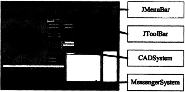
the authors propose a collaborative CAD system that could simultaneously modify a design file, although their program seems to be geared mostly towards architectural design. In the prototype, the program exhibits solely collaborative functionality, with an added messaging console to aid in communication. Commenting and record keeping are absent, as is the fundamental focus on conceptual design. Figure 3-1 shows a screenshot of the ROCCAD prototype.
JMI2arZ
JToolBar
I
CADSystm
MMM• ... W
Figure 3-1: Screenshot of authors' ROCCAD program26
3.3 Literature Impact
Although most of the literature that focuses on conceptual design and CAD systems is not immediately applicable to this thesis, the literature in the last few years regarding
collaborative computing are steps in the right direction in creating a more effective 25 Chen, Hung-Ming & Hung-Chun Tien. "Application of Peer-to-Peer Network for Real-Time Online
Collaborative Computer-Aided Design." Journal of Computing in Civil Engineering, Vol. 21, No. 2, March 1, 2007. ©ASCE pp. 112-121
26 ibid. pp. 119
design system. However, little action occurred before the ROCCAD prototype & the DCCAD plug-in appeared. And while the ROCCAD prototype, unveiled in March of 2007, will help push the CAD industry towards adopting a more collaborative
architecture, more needs to be done to ensure that a collaborative and conceptual program is born.
Chapter 4
Research & Methods
4.1 Current Product Analysis
In order to begin development of a software specification for DC-CAD, one must first consider current solutions and determine where features in current software are lacking. A well designed software package must also be built to encompass the structure of the conceptual design process: certain needs exist in preliminary-phase designing that are not necessary in detailed design programs. CAD packages such as Solidworks and ProE help engineers do detailed designing and prototyping of near-final products or mockups. All packages have 3-dimensional capabilities while most offer surface and structural features to further detail products with computer software. The ability to easily change the design varies by product. The downside of using such a detailed program to do conceptual design work is three-fold: 1) current CAD systems require intensive work to create simple geometries and force the user to create complete geometries, when typical concept designs include incomplete geometries and subsystems27; 2) detailed designs at an early
stage can lead to lock-in on one particular idea and limit creativity28; and 3) few to none of the current solutions encompass early-stage design features such as collaborative
27
Dani T.H.; Gadh R. ibid.
modification and conceptual sketching. In sum, current CAD systems do not meet the needs of conceptual designers in a globally distributed industry.
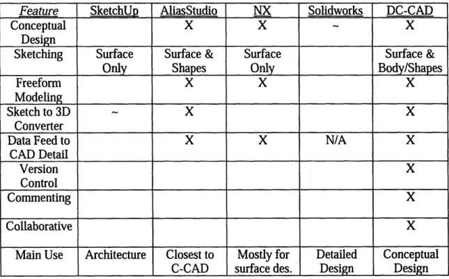
In order to identify specific features lacking in current CAD & CAID systems, 4 systems were selected that represent the differences across the current CAD spectrum: Google SketchUp, AutoDesk AliasStudio, Unigraphics NX, & Dassault's Solidworks. Table 4.1 compares the four regarding their utility for conceptual, distributed design. For a more comprehensive list of CAD solutions, please see Appendix A in Chapter 7.
Table 4.1: Current CAD System Comparison
Feature SketchUp AliasStudio NX Solidworks DC-CAD
Conceptual X X - X
Design
Sketching Surface Surface & Surface Surface &
Only Shapes Only Body/Shapes
Freeform X X X
Modeling
Sketch to 3D X X
Converter
Data Feed to X X N/A X
CAD Detail
Version X
Control
Commenting X
Collaborative X
Main Use Architecture Closest to Mostly for Detailed Conceptual
C-CAD surface des. Design Design
As can be seen from Table 4.1, even the top CAD providers do not provide the essential functionality required for a true conceptual design program. AliasStudio is the closest fit to a conceptual design program, but it lacks any collaborative or editing features. Alias is also mostly used for industrial design of surfaces (for the Aero & Auto industries), not
consumer products. While using Alias could serve as a short term fix, the real solution is to create a real concept design system that can be both collaborative (such as ROCCAD)
and conceptual.
4.2 2.009 Design Experience
MIT's senior-year, fall term class titled "2.009: The Product Engineering Process" is an excellent model for existing product design processes. Although the timeline for this class is short and limited, it nonetheless serves as a good example in order to determine key areas and features that would be needed for a DC-CAD solution. The class places students into fifteen-person teams; each team proceeds on an abbreviated product design cycle including the four stages of Problem Identification, Conceptual Design, Detailed Design, and Product Fabrication. By analyzing problems that arose during the design phases and how a solution such as DC-CAD could have helped, the solution created should be useful not only for a setting like 2.009, but for the greater engineering design industry.
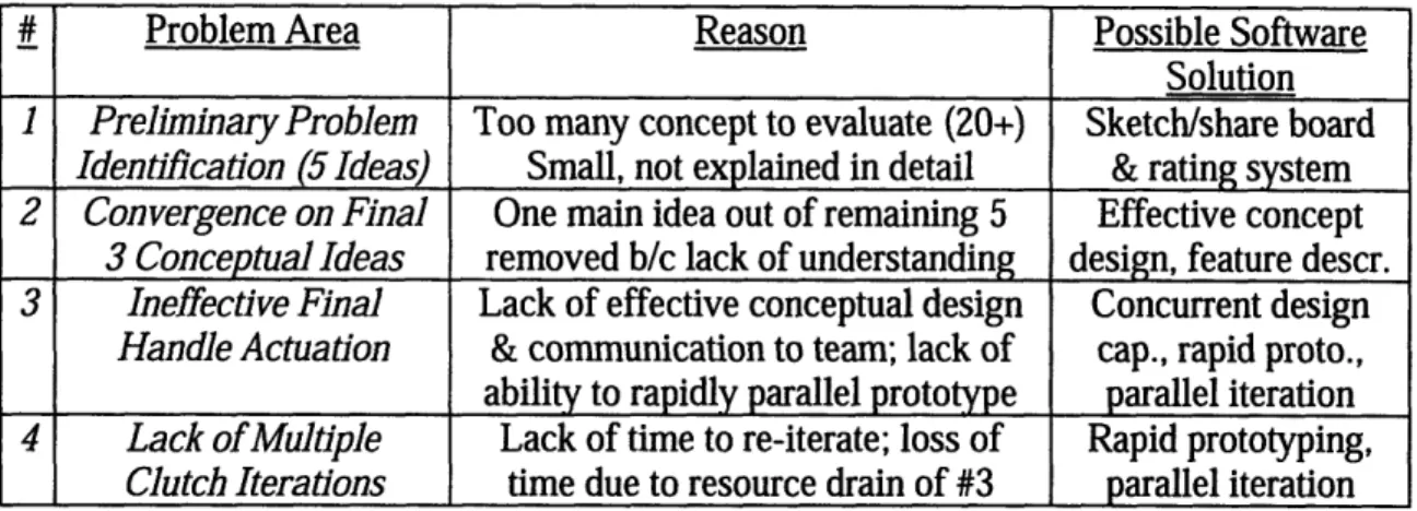
During my semester in 2.009, my team was tasked with creating a product within the realm of improving communication challenges for the physically and mentally disabled. During three of the four stages of the development cycle we ran into major design issues, issues that would have likely been mitigated had we used a conceptual design software package. Table 4.2 outlines the four problem areas that arose during the course of the class.
Table 4.2: 2.009 Design Process Challenges
# Problem Area Reason Possible Software
Solution
1 Preliminary Problem Too many concept to evaluate (20+) Sketch/share board
Identification (5 Ideas) Small, not explained in detail & rating system 2 Convergence on Final One main idea out of remaining 5 Effective concept
3 Conceptual Ideas removed b/c lack of understanding design, feature descr. 3 Ineffective Final Lack of effective conceptual design Concurrent design
Handle Actuation & communication to team; lack of cap., rapid proto.,
ability to rapidly parallel prototype parallel iteration
4 Lack of Multiple Lack of time to re-iterate; loss of Rapid prototyping, Clutch Iterations time due to resource drain of #3 parallel iteration
For problem case number one, each member of the team was tasked with creating, sketching, and explaining five ideas for products within our scope of topic
(communication challenges). However, because there were twenty hand-sketched
drawings pinned onto a board relatively far away from the team table as we tried to make out the best designs, it was difficult to accurately compare each drawing from a sheer conceptual standpoint. Ideas certainly fell by the wayside during this exercise; this problem could have been easily mitigated by having access to a digital 'corkboard' where concept 'sketches' could be digitally attached to a discussion board, viewable from each team member's DC-CAD program on their personal computer. By being able to digitally zoom in and compare each sketch at face value, including seeing any notes attached to such a sketch, the ability to comprehend and critically evaluate ideas would be greatly
improved. By adding the additional feature of a network-oriented sketch scoring or rating system, the best ideas could be selected. The ultimate power of such a 'share board' would be the power to incorporate multiple file formats into one common
application, DC-CAD. Sample formats could include JPGs, scanned hand sketches, paint files, 3D studio files, or even standard .dwg or other solid model files.
For problem number two in table 4.2, the reason behind the problem was similar. In trying to narrow down five conceptual design choices into our final three concepts slated to be presented to our class, one interesting idea was immediately thrown out simply because the hand sketch did not adequately portray the potential of the concept. Although the idea was complex, if the group had had an electronic representation with an attached list of features and risk assessments, it would have been very beneficial and perhaps saved one of the most interesting projects of the semester. To solve this, the ability to have a program that quickly designed block concepts and attached a summary list of features & design risks could greatly help design and concept review sessions at the early design stages.
For design issue number three, adequate early stage conceptual design was the ultimate reason why that part of the project failed. On our final product, we had a
pivoting handle that had a handle actuator connected to a stable-closed clutch. Our initial team that designed the system did not have the time to fully prototype three conceptual models for the clutch actuation system, so they picked the first system they were able to conceptually prototype in SolidWorks, a detailed design program. Since they did not have the best tools to communicate their concept idea to the rest of the team until the remainder of the system was built and unsuccessfully implemented, we had to completely redesign the actuation system two weeks before the project deadline, pulling critical members of other teams onto the failed clutch actuation team. This contributed to the lack of full prototyping of our actual clutch system (problem issue number four), since key members got pulled off and onto the failed team. Here, concurrent design
capabilities would have greatly helped in such a crunch situation. Also, the ability to rapid prototype with parallel iterations would have been very beneficial.
In sum, several key software features of a prospective DC-CAD system were identified during these critical design turning points throughout our semester in 2.009. One major lesson was learned during the 2.009 experience: detailed design systems are inadequate and time consuming for conceptual design. After considering current CAD system deficiencies and using 2.009 as a case study for DC-CAD implementation, it is now time to identify the concrete features that such a distributed, conceptual design program should possess.
4.3 The 'DC-CAD' Vision
The features of the 'DC-CAD' focus on performance and accountability from a
conceptual design standpoint and the ability to enable distributed (collaborative) design. They also result from the deficiencies identified in current CAD systems, as well as a result of the challenges that arose over the course of 2.009.
4.3.1 Distributed Design
The first unique need that DC-CAD solves centers on collaborative modification and geographically distributed design teams. In an era of globalization, design teams are not
necessarily all present in the same location as design occurs. No current CAD solutions address this need other than the ROCCAD prototype discussed earlier; DC-CAD should therefore enable multiple users from distributed locations to access and modify the same design. The three possible architectures include client-server, P2P, & web services.
Regardless of the choice of architecture, the structure of the relationship between the users and the file will need to be one of continual merging and verification, similar to the architecture of CVS or Subversion, an open-source version control system. Another option for maintaining a system of distributed modification of a single file would be to lock individual features if they are being modified by a user, as opposed to locking the entire file as is typically the case. For world-wide access and interconnection with a messaging service, a web service approach may be the best architecture to pursue.
4.3.2 Conceptual Design
Instead of using pencil and paper, designers should be using a computer driven system to help them conceptualize their ideas. Some possibilities include an easy to use CAD program that makes quick generation of 2D and 3D sketches simple and intuitive, integration with tablet PC computers, palm pilots, pocket PCs, virtual reality design media. Another alternative could involve importing sketches or creating sketches natively in the DC-CAD program. The program would then need to have a converter to translate the 2D drawing into a 3D representation of the product design. In order for effective 3D design to reach its full power, the program would need to be capable of changing conceptual options quickly, such as the conversion of a two-wheel bike into a three-wheel bike, literally at the click of a mouse.
4.3.3 Communication
Lastly, the program must be able to effectively aid in the communication of the concept to other designers. In doing so, it will need both active and passive forms of
communication tools. Passive tools would include a database of 'concept records.' This will enable the tracking of design changes and allow the ability to include reasons that were associated with design or concept changes, allowing quick and easy understanding of how the design evolved with time and with multiple authors. This will greatly aid in the design review abilities of designers and their ideas. Also, the ability to comment and edit a document and send the commentary back to the original designer(s) with the ability
to incorporate (merge) or discard changes made will enable more effective design modifications. Two forms of active communication would include an in-program
messenger capability to communicate with other concurrent designers, as well as a digital 'Share Board' that would enable team members to 'post' 'sketches' of concepts for discussion and evaluation. The ability to list key features and risk points and tag them to the concept on the board will be crucial. Having an in-program rating system to evaluate the concepts would also contribute to the utility of the program with respect to the design process.
4.3.4 Life Cycle Design Continuity
The program would need to embody these functionalities, as well as the ability to pass necessary data to a detailed design package such as SolidWorks or ProE to continue the design into the detailed design phase. Without the ability for continuation into the next phase of design, one will lose a large degree of utility of the program.
With these tools and features, the ability of a designer to conceptualize a product at an early stage will be greatly enhanced with the utilization of DC-CAD during the design
process. The greatest utility will come from using a combination of these features at the same time. For example, a team of designers could hold a meeting and simultaneously be discussing (thanks to the Share Board capability) and modifying the concept each with their own laptop (thanks to the distributed & collaborative feature) as they hold the meeting around a projector screen featuring the product concept. Better yet, the group could be holding a teleconference from separate countries, performing the same tasks as
if they were in the same room together.
Given this new product vision, this thesis will demonstrate with a hypothetical case study of a future 2.009 design experience - using DC-CAD. Figure 4-1 shows a graphical representation of the features of DC-CAD, and Figure 4-2 is a hypothetical screenshot of what the program could look like.
/n
i
fl5~o
FiguDC-IM O lemul0"
FiguDC--e 4-2: DC-CAD Hypothetical:
4.4 A 'DC-CAD' Storyboard
-
A Hypothetical DC-CAD Example
As a new semester of 2.009 starts at MIT (in 2012), this year's students get to experience a new facet in engineer design: the industry's newest CAD addition, DC-CAD. Each student has a copy of the program installed on their own laptop; coupled with Solidworks and a new WebCollab2 9 middleware program, the students are ready to explore the
engineering design world and solve this year's problem, unmanned autonomous race vehicles.
The first week the multiple teams of seven students are assigned to create five ideas each; each has been asked to sketch concepts in whatever medium they choose, but 29 WebCollab is a purely fictional middleware program invented for this example to serve as both the
web-backend connecting DC-CAD to the client-server web-backend & the streamlined pathway from DC-CAD into Solidworks as a 3D assembly of parts
they must post their ideas to the 2.009 Share Board associated with their team. During the ideas discussion session, the students are able to use this new tool to highlight any of the thirty-five concepts they see and want to evaluate with a closer eye before ranking their top five choices, five being highest, and one being the lowest. At the end of the assessment period that first week, the team has efficiently narrowed the field to five ideas, after a few informative debates due to ranking ties between some of the ideas. However, armed with the feature and risk outlines for each concept, the ties were easy to break.
Two weeks later, the students are meeting again; in an attempt to narrow their ideas from five down to three, three sub-teams are making mini-presentations regarding their concepts and the multiple conceptual iterations they have quickly developed in DC-CAD. With the software's inherent 'concept' copy ability, a concept can be copied from its original form and then modified into another iteration quite easily, sometimes after just a few clicks of the mouse. Once the group has gotten the number down to four, one
of the students, John, points out that one of the remaining two concepts (they must decide on one between the remaining two, as two have already progressed through) could be much better improved if the wheel base was rotated 180 degrees - in essence, reversed to be a rear-facing triangle. Since some of the students ask for a clarification, he quickly goes into the program and opens the file that is on display on the projector... and creates a new iteration with the reversed configuration in a matter of seconds. The room
instantly lights up, and the new design makes it through to the next round of evaluations. Several weeks later, John and his team have moved onto the detailed design of the final product. John is in the middle of comparing the concept design and its linked notes
in his copy of the DC-CAD program while a team member finishes the last touches on the part that he has to now detail in Solidworks. After he has already transferred the file into Solidworks' assembly format as a series of parts and separate assemblies, John
notices that the brake system they had designed in DC-CAD will interfere slightly with the motor system in place to propel their race vehicle (the rear-facing triangle of several weeks ago). (Solidworks has alerted him that a collision has occurred!) But he has
already converted the files into Solidworks form! John realizes that there is no problem, as he goes back to the DC-CAD format, changes the conceptual design to eliminate the interference, and resends the files back to Solidworks for a second iteration of the detailed design he now has to expand and complete. 'What a relief,' he thinks, as he realizes how costly the mistake could have become had the brake and propulsion systems both been manufactured without seeing the problem in the change between DC-CAD & Solidworks...
Another four weeks later, John's team wins the 2.009 race vehicle competition, thanks in part to the ease of using DC-CAD seamlessly with Solidworks. He didn't even have to pull a single all-nighter for the entire semester! After his graduation, John goes on to work for DefenseXYZ, one of the newest leading defense contractors building the next generation of unmanned military reconnaissance vehicles. During his first week there, his boss comes and asks him if John thinks he'd be able to use a new program the
company just bought to do some initial designs for parts of the new Army Recon Vehicle. Some of the designers in California (John is based in Boston), are working other parts of the project, and there is a meeting the following week for the two groups to come
together and combine their concepts. When John hears that the program is DC-CAD, he smiles. "No problem boss, I'll be sure to have the models done by next week."
While somewhat of a fantasy demonstration, the utility of DC-CAD for 2.009 and in the professional design world is not far from reality. The technology exists in either research form or practical form in a variety of other programs; DC-CAD represents the ultimate synthesis of conceptual CAD systems, including some features still yet to hit the CAD market, such as practical collaborative design. Figure 4-3 recaps the power of DC-CAD as depicted in the story detailed above.
I
Figure 4-3: DC-CAD Storyboard
I
I" , I
4. With DC-CAD problems are identified & fixed eam presents more easily
ts; w/ DC-CAD,
changes
can De madeL
nn ferren real-time 2. Designers discuss & evaluate ideas via DC-CAD5. With the help of DC-CAD, design
1. Designers teams can enjoy
conceptualize ideas success at a faster rate via sketching &
imPort to DC-CAD
I I
riýý
i _1_ L ____~_ I
Chapter 5
Lessons Learned & Significance
Throughout the completion of the thesis, I learned a great deal about how far CAD has advanced since I first began using AutoCAD 2000 several years ago. The
interconnectedness of CAID applications, from surface design, to detailed design, and then onto Computer Aided Manufacturing (CNC machining), represents a powerful tool for designers. However, large holes still exist despite the explosion of IT into diverse sectors of the business market. CAID represents a step in the right direction, but projects like ROCCAD & DC-CAD will help push the market further towards its maximum
utility.
While CAID programs represent a step in the direction of conceptual CAD, more needs to be done in the industrial design market for collaborative design products. So far no products have come out to utilize this new technology that will have large implications for engineering design. Some initiatives are in place to strive for a true 'DC-CAD'
solution, such as the ROCCAD prototype. My prediction is that the first-to-market of an ideal DC-CAD program with a geographical distributed solution will force the market to converge on some of these new features and specifications. Lastly, as shown with the realistic and palpable 2.009 case study, DC-CAD will greatly improve the design experience for both students and professional designers alike.
Chapter 6
Recommendations
In summary, DC-CAD will be a novel conceptual CAD program that will have the capability of linking distributed designers on the same project, simultaneously. It will also serve as a crucial communication tool for design specifications, changes, and evaluations. Lastly, it will help shorten the development cycle & improve quality by increasing the knowledge base of the designer at a phase when decisions make critical cost impacts on the product.
In order to pursue a realistic DC-CAD implementation, a software specification will need to be detailed in coordination with both professional designers and software programmers. Contacting major CAD/CAID providers will help determine their level of interest in a new solution such as DC-CAD, which will help engage appropriate
stakeholders to take on the financial and technical challenges of such a project. DC-CAD and its key features are sure to make an impact in the world of CAD and engineering design in the near future. The extent of that impact will depend on the market's interest in pursuing this new and emerging technology.
Chapter 7
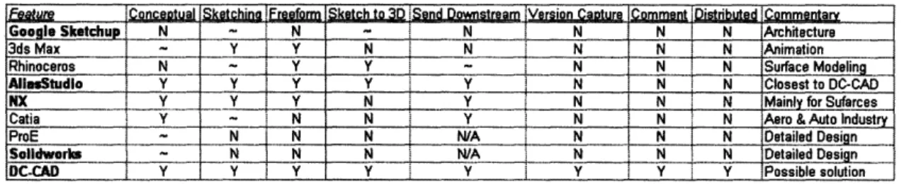
Appendix A: CAD Comparison
Go le Sketchup N ... N N N N N Architecture
3dsMax - Y Y N N N N N Animation
RhinocrosN N N Surface Modelin
AllStudio IY yY Y Y N N N Closest to DC-CAD
NX Y Y I Y N Y N N N Mainly for Sufarces
Catia Y - N N Y N N N Aero & Auto Industry
ProE ~ N N N N/A N N N Detailed Design
Soldworks N N N NA N N DetailNed •n
DC-CAD I Y Y Y Y Y Y Y I Y Possible solution
Table 7.1: CAD Comparison
Google SketchUp, AliasStudio, NX, & Solidworks were chosen as the four program most representative out of these programs to compare with DC-CAD. They represent the four main areas of the spectrum in CAD & CAID programs. SketchUp is mainly for
sketching, but in the architectural realm, AliasStudio is capable of sketching and concept design but has several deficiencies limiting its utility in distributed, conceptual settings.
NX is enveloped in a suite of software as part of the conceptual stage but focuses mainly
on surface, not body conceptual design. Lastly, Solidworks represents the detailed design realm of CAD systems today.