DEVELOPMENT OF THE PROCESS PARAMETER MAP FOR
REFERENCE FREE PART ENCAPSULATION
BY
CEANI GUEVARA
S.B.,
MECHANICAL ENGINEERING, 2000 MASSACHUSETTS INSTITUTE OF TECHNOLOGYSUBMITTED TO THE DEPARTMENT OF MECHANICAL ENGINEERING IN PARTIAL FULFILLMENT OF THE REQUIREMENTS FOR THE DEGREE OF
MASTER OF SCIENCE IN MECHANICAL ENGINEERING AT THE
MASSACHUSETTS INSTITUTE OF TECHNOLOGY BARKER
JUNE2001 ~iMS CHUSETTS INSTIrUTE
OFTECHNOLOGY
C 2001 Massachusetts Institute of Technology JUL 16 2001 All rights reserved
LIBRARIES
Author:.-.-.
-.-Department of Mechanical Engineering May 11, 2001
Certified by: ... ... S a. S
Sanjay E. Sarma Associate Professor of Mechanical Engineering Thesis Supervisor
Accepted by:
Ain A. Sonin
Professor of Mechanical Engineering Chairman of the Graduate Thesis Committee
Development of the Process Parameter Map for
Reference Free Part Encapsulation
by
Ceani Guevara
Submitted to the Department of Mechanical Engineering on May 11, 2001 in Partial Fulfillment of the Requirements for the Degree of Master of Science in
Mechanical Engineering
ABSTRACT
A paradigm shift needs to occur so that manufacturing processes are able to
simultaneously improve in quality, rate, and flexibility while reducing cost. Fixturing methods currently available represent an important constraint on manufacturing systems. The Reference Free Part Encapsulation (RFPE) concept, developed by Sarma and Wright, seems to be the paradigm shift required to improve the capabilities of the fixturing technology across the board.
While Lee has proved the viability of the RFPE process experimentally, much work remains to be done before the process can complete the journey from idea to reality. Therein lies the motivation for this study: to establish a framework to understand RFPE, consolidate the existing knowledge, identify the critical factors that remain unexplored, determine the impact these factors have on the process, and thus develop a process parameter map of the RFPE concept.
The following process parameters were identified: melt superheat temperature, mold preheat temperature, ejection temperature, cooling rate, packing pressure, aging, and
alloy composition. These parameters were measured via metrics such as surface finish, porosity, dimensional accuracy, thermal drift, and rewelding strength. The RFPE Process
Parameter Map was completed based on the information obtained through
experimentation, analysis, and literature review. The melt superheat temperature, mold preheat temperature, packing pressure, and cooling have the potential to impact the precision of the system. These experiments have identified the process window within which the RFPE concept is not sensitive to variations in these process parameters. The ejection temperature, aging and alloy composition do not seem to have a significant impact on the precision of the process. The process parameter map forms a solid foundation from which future developments of the RFPE process can take place. Thesis Supervisor: Sanjay E. Sarma
Table of Contents
CHAPTER 1: BACKGROUND AND MOTIVATION ... 15
1.1. Role of Fixturing in Manufacturing...16
1.2. Functional Requirements of Fixturing...16
1.3. Current Fixturing Technology...19
1.3.1. Modular Fixturing Systems ... 19
1.3.2. Universal Fixturing Systems ... 20
1.3.2.1. Conformable Clamps ... 20
1.3.2.2. Fluidized Bed... 21
1.3.2.3. Phase Change Material ... 22
1.3.3. Limitations of the Current Fixturing Technology ... 23
CHAPTER 2: REFERENCE FREE PART ENCAPSULATION... 25
2.1. The Ideal Fixturing System...25
2.2. The RFPE Concept ... 26
2.3. Capabilities of RFPE ... 28
2.4. Three Machining Strategies: 2D, 21/2D, and 3D Milling ... 29
2.4.1. 2D M illing ... 29
2.4.2. 2 2D Milling ... 30
2.4 .3. 3D M illing ... 31
2.5. Motivation...32
CHAPTER 3: FRAMEWORK TO ANALYZE AND DEVELOP RFPE ... 33
3.1. The Building Blocks of a System ... 33
3.2. Design and Process Parameters...33
CHAPTER 4: SYSTEMATIC EVALUATION OF
PARAMETERS AND METRICS... 37
4.1. M etrics of the RFPE Process ... 37
4.1.1. Surface Finish... 37
4.1.2. Porosity... 38
4.1.3. Dimensional Accuracy ... 39
4.1.4. Thermal Drift... 39
4.1.5. Rewelding Strength ... 40
4.2. Process Parameters: an Overview... 41
4.2.1. Temperature... 42
4.2.1.1. Melt Superheat... 42
4.2.1.2. Mold Preheat Temperature ... 43
4.2.1.3. Cooling Rate ... 43
4.2.1.4. Ejection Temperature... 44
4.2.2. Packing Pressure... 44
4.2.3. Aging ... 47
4.2.4. Alloy Composition ... 47
4.3. The A Priori RFPE Process Parameter M ap ... 48
4.4. Next Steps ... 50
CHAPTER 5: EXPERIMENTAL PLAN... 51
5.1. Objectives of the Experiments... 51
5.2. Experimental Apparatus... 51
5.2.1. The Mold ... 51
5.2.2. Instrumentation...52
5.3. Experimental Procedure ... 53
5.3.1. The Effect of and the Interaction between Melt Superheat and Mold Preheat Temperature ... 54
5.3.2. The Effect of Cooling Rate ... 55
5.3.3. The Effect of Ejection Temperature ... 55
5.3.4. Aging Effects... 55
5.3.5. The Interaction between Packing Pressure and Cooling Rate...56
CHAPTER 6: THEORETICAL BACKGROUND FOR
EXPERIMENTAL ANALYSIS ... 57
6.1. The Impact of Surface Finish...57
6.1.1. The Mechanism of Surface Deflection Under Load ... 58
6.1.2. Quantification of the Possible Deflection of the Asperities ... 59
6.1.3. The Variables for Roughness Measurements as it Relates to D eflection ... . 60
6.2. Im pact of Porosity... 61
6.2.1. Form ation of Porosity... 61
6.2.2. Classification of porosity: Macroporosity and Microporosity ... 62
6.2.3. Porosity and the RFPE Process ... 63
6.3. Temperature Drop from the Mold Cavity to the Thermocouple Well...63
6.4. Variations in Cooling Rate...65
CHAPTER 7: EXPERIMENTAL RESULTS ... 67
7.1. The Effect of Melt Superheat and Mold Preheat Temperature...67
7.2. The Effect of Ejection Temperature ... 69
7.3. The Effect of Cooling Rate...69
7.4. Aging Effects... 70
7.5. The Interaction between Packing Pressure and Cooling Rate ... 71
7.6. The Effects of Alloy Composition... 71
CHAPTER 8: THE RFPE PROCESS PARAMETER MAP... 73
CHAPTER 9: FUTURE WORK... 77
9.1. Study of Design Parameters... 77
9.2. Design of a Field Trial Prototype ... 77
APPENDIX A: AN INTRODUCTION TO THE RFPE DESIGN
PARAM ETERS ... 81
A.1. Parameters Affecting the Alloy Storage and Delivery... 83
A.1.1. The Reservoir ... 83
A. 1.1.1. Reservoir Temperature... 83
A.1.1.2. Proportion of New to Recycled Alloy ... 84
A. 1.1.3. Reservoir Construction ... 84
A.1.2. Alloy Delivery... 85
A.l.2.1. Injection Pressure...86
A.1.2.2. Shot Size ... 86
A.1.2.3. Rate of Change in Pressure ... 87
A.1.2.4. Pressure on Opposing Sides of the Injection Piston ... 87
A.1.2.5. Inertia Effects...87
A.l.2.6. Transfer Tubing Design...87
A.1.2.7. Partial Blockages of the Metal Stream...88
A.2. Parameters Affecting the Introduction and Behavior of Alloy Inside the Mold 88 A.2.1. Gate Velocity...88
A.2.2. Cooling Direction...89
A.2.3. Heating and Cooling of the Mold... 89
A.2.4. Mold Surface Finish... 89
A.2.5. Mold Material Selection... 90
A.2.6. Mold Locking Pressure ... 90
A.2.7. Mold Vents ... 90
A.2.8. Compatibility of Gate and Machined Section Geometry ... 91
List of Figures
Figure 1: The lack of locating stability or deterministic workpiece location can introduce variations in the position or the orientation of the part. Even a small variation in orientation can cause a significant error in the precision of
th e w ork p iece ... 17
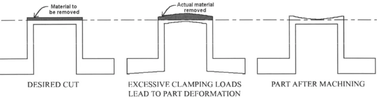
Figure 2: Excessive clamping loads can deform a workpiece. This deformation can affect both the dimensional accuracy and the structural integrity of the w orkpiece ... 18
Figure 3: The inability of a workpiece to transmit the localized fixturing support force throughout the part causes a loss of dimensional accuracy. In effect, the workpiece deflection under machining loads results in a lack of to tal restrain t. ... 18
Figure 4: Conformable clamp fixturing ... 21
Figure 5: Fluidized bed fixturing ... 22
Figure 6: Phase change fixturing ... 23
Figure 7: The Reference Free Part Encapsulation (RFPE) Process ... 27
Figure 8: Sample parts produced with RFPE...28
Figure 9: 2D M illing ... 29
Figure 10: 2!/2D M illing ... 30
Figure 11: 3D M illing ... 31
Figure 12: A plot of the relationship between each process parameter and each metric for a system facilitates an understanding of the system ch aracteristics...34
Figure 13: Each process parameter typically impacts multiple metrics of the same system. Often, there is no optimum setting for the process parameter. Therefore, tradeoffs between the metrics are required. ... 34
Figure 14: Design parameters determine the range of each process parameter that is feasible for each implementation of the concept...35 Figure 15: For the particular implementation modeled in this diagram, the
choice was made to have the design parameters favor Metric #1 slightly over
Figure 16: A surface finish can be categorized by the amount that it deviates from a perfectly flat surface. There are three ways in which this deviation
occurs: form error, waviness, and roughness...38
Figure 17: H ow therm al drift occurs... 40
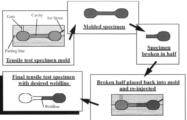
Figure 18: Creation of weldline test specimens...41
Figure 19: The peak-to-valley heights of all specimens and inserts used to characterize surface finish... 45
Figure 20: RFPE process window for packing pressure versus mold surface rou g h n ess ... 4 6 Figure 21: The A Priori RFPE Process Parameter Map ... 48
Figure 22: Interaction matrix for the RFPE process parameters...49
Figure 23: Mold used to produce experimental specimens ... 52
Figure 24: LabVIEW control program screen shot...53
Figure 25: Experim ental setup ... 54
Figure 26: Model of surfaces as flat, and in perfect contact...57
Figure 27: Asperities reduce the real to nominal surface area ratio ... 57
Figure 28: Profilometer trace for a 0.4 pm surface, with no wavelength filterin g ... 5 9 Figure 29: Temperature drop due to conductive resistance as a function of h eat tran sfer rate...64
Figure 30: Cooling rate of mold in air and in ice water...70
Figure 31: Comparison of the cooling rate of a pressurized and unpressurized m o ld cav ity ... 7 1 Figure 32: Completed RFPE Process Parameter Map ... 74
Figure 33: Completed interaction matrix for the RFPE process parameters ... 75
Figure 34: Rapid Prototyping Center... 78
Figure 35: The Rapid Prototyping Center will transform the manufacturing process from a heavy manual intervention process into a black box...79
List of Tables
Table 1: Peak-to-valley depth for various surface roughness standards...60 Table 2: Roughness, summit curvature, and deflection values of the surface
roughness standards ... 60
Table 3: Description of the surface condition as a function of the injection
temperature and mold preheat temperature... 67
TkanL You
To mg familg To mg friends To mg mentors
I dedicate this thesis to the memory of
M3 Grandfather, Opa, Ernst
5. Keizer
Who taught me Math, Persistence, UJnderstandingand to
M
Grandmother,
Oma,Kuth
KeizerChapter 1: Background and Motivation
Manufactured goods are prevalent in our society. These goods decrease the time, reduce the effort, or provide the tools required to accomplish a task. The span of these goods ranges from the very mundane, such as scissors or a wrench, to the highly complex, such as an automobile or a heart pump. We use manufactured products daily, yet most of us rarely stop to question how they were produced. When we purchase them, we want them to be cheap, yet we expect them to be durable and perform as advertised. These
requirements percolate through to drive the goal of manufacturing systems: to produce high quality, low cost products quickly in flexible set-ups. Unfortunately, these goals tend to be competitive in nature, with advances in one area often requiring concessions
from the other metrics. In this way, incremental advances to the existing manufacturing systems can only have extremely limited effects. Thus, a paradigm shift is needed to raise the bar simultaneously on all four criteria used to evaluate manufacturing systems. The first question we may want to ask is where this paradigm shift needs to occur. Do we need to change the entire manufacturing process as we know it, or is it possible to identify a key aspect that will enable the overall improvement we are looking for? In any system, some areas are always more capable than others. Whichever aspect lags behind the others becomes a critical link, limiting the overall potential of the system. Chapter 1 of this thesis argues that current fixturing technology is this critical link of both the design process and of most manufacturing systems. Once the motivation for developing a novel fixturing system is established, Chapter 2 introduces the Reference Free Part Encapsulation (RFPE) concept-a paradigm shift. Chapter 3 establishes a framework for the foundation necessary to analyze and develop the RFPE process. With this structure in place, Chapter 4 both identifies the parameters of this process that have the potential to affect the outcome and defines RFPE's measurable objectives. This chapter also summarizes the insights gained from a literature review and from previous research. Next, Chapter 5 discusses the design of experiments conducted to fill in the gaps in understanding the impact of and interaction between the various process parameters. The theoretical background necessary to analyze the data from these experiments is presented in Chapter 6. Chapter 7 presents the results of these experiments. Then, Chapter 8 presents the RFPE Process Parameter Map. The understanding provided by this map will help unearth the full potential of the RFPE process. Chapter 9 suggests avenues for further research, and speculates about RFPE's effect on the manufacturing process. To realize the potential contribution of RFPE, it is important to understand the role of fixturing in manufacturing. Section 1.1 begins by discussing the role of fixturing in manufacturing and its repercussions on the design process. Next, Section 1.2 reviews the functional requirements of fixturing. Finally, Section 1.3 presents the current fixturing technology.
1.1.
Role of Fixturing in Manufacturing
Manufacturing is the process by which a product is brought from design to production, from idea to reality. In an ideal scenario, the design will achieve the functional
requirements set by the designer in the simplest possible manner. However, in reality, the designer must take into account various limitations. In particular, the designer must consider the cost and physical limitations of the different manufacturing processes. One important limitation in manufacturing is defined by the capabilities of the fixturing systems available. Fixturing is the critical link between idea and reality in a unit
production system. Fixturing holds the workpiece in the desired orientation so that various manufacturing processes can be brought to bear on the component. In many ways, the quality of the component is determined by the limitations of the fixturing
system itself. Furthermore, demands that a particular design places on a fixturing system translate directly into financial and temporal costs born by the final product. These challenges can be illustrated through an examination of the impact of fixturing on machining processes.
Machine tools, especially with the aid of CNC, are capable of creating a great variety of geometries. Recent strides in precision machine design have resulted in continued improvement in the precision, power, and flexibility of tools. However, limitations in current fixturing technology greatly restrict the shapes that can actually be produced. In fact, designers must often increase the complexity of the part and the production process to compensate for deficiencies in the fixturing systems. This, in turn, leads to an increase in the cost and a decrease in the production in order to produce the part at all. Thus, the creativity of the designer is curbed by the capabilities of the fixturing systems available. Advances in this field would clearly have a positive impact on the manufacturing world. Therefore, a new fixturing system would be most welcome. The goals of this new fixturing system are driven by the functional requirements of fixturing and the characteristics and limitations of the current workholding systems.
1.2.
Functional Requirements of Fixturing
In order to compare a variety of fixturing methodologies, it is important to establish the goals of a fixturing system. This permits an objective evaluation of each system. Any
fixturing device must achieve some basic characteristics for it to be called a fixture. For example, a fixture must provide the machine with access to the workpiece. Additionally, a fixture should not destroy a workpiece. If the "fixture" does not meet either of these characteristics, the device is effectively useless. For the purpose of discussion within this thesis, these basic characteristics are assumed to be met implicitly by any device called a fixture. Additionally, it is assumed that in evaluating fixtures, the goals of manufacturing will be considered. Therefore, properties such as the production rate and production cost dictated by the fixture need to be considered. However, before we can even begin
duty. To do this, there are some finer requirements that these fixtures should achieve to enable them to perform their function properly. These functional requirements of fixturing systems are fourfold: locating stability, deterministic workpiece location, clamping stability, and total restraint.*
Locating stability implies that the workpiece must achieve a stable position as it is placed into a fixturing device. Deterministic workpiece location signifies that the position of a workpiece must be precisely known to ensure the accuracy of the machining operations. Clamping stability establishes that the equilibrium and accuracy of the workpiece position should not be disturbed while the clamping forces are applied. Total restraint means that once the clamping forces have been applied to the workpiece, it should remain immobile for the duration of the machining operation.
The quality of a machined part is limited by the fixturing system used during the production process. Even with the use of the best machine tools available, machining processes can achieve the desired level of quality only if the fixture satisfies its four functional requirements. The fixture's limitations in achieving these functional requirements lead to errors introduced into the workpiece. For example, the lack of locating stability or deterministic workpiece location can introduce variations in the position or the orientation of the part. Figure li shows that even a small variation in orientation can cause a significant error in the precision of the workpiece.
.,-Material to -Actual material
DESIRED CUT ORIENTATION ERROR PART AFTER MACHINING
Figure 1: The lack of locating stability or deterministic workpiece location can introduce variations in the position or the orientation of the part. Even a small variation in orientation can cause a significant
error in the precision of the workpiece.
The fixture's ability to locate the part accurately is not sufficient in and of itself. Any precision gained through locational accuracy and stability is readily lost when clamping loads are applied incorrectly. Figure 2 shows how excessive clamping loads applied to a
* Chou, Y.-C., Srinivas, R.A., and Saraf, S., "Automatic Design of Machining Fixtures: Conceptual
Design," International Journal ofAdvanced Manufacturing Technology, Vol. 9, 1994, pp. 3-12.
i Kapoor, S., "New FEM Modeling Results for Fixture/Part Contact," AMRI Machine Tool Workshop on Agile Fixturing, The University of Michigan, Ann Arbor, MI, July 25, 1996, p. 4.
workpiece can result in deformation of the part. This deformation causes too much material to be removed during the machining operations. Such an error can affect both the dimensional accuracy and the structural integrity of the workpiece.
Material to Actual material
DESIRED CUT EXCESSIVE CLAMPING LOADS PART AFTER MACHINING
LEAD TO PART DEFORMATION
Figure 2: Excessive clamping loads can deform a workpiece. This deformation can affect both the dimensional accuracy and the
structural integrity of the workpiece.
Finally, one cannot neglect total restraint, the fourth and final functional requirement of fixturing systems. Unfortunately, this requirement is often difficult to achieve. Ideally, once the workpiece has been clamped to its supporting elements, the fixture prevents the workpiece from shifting from its desired position, regardless of the machining operations that are performed on it. In reality, the supporting elements and holding forces are
typically applied over localized regions of the workpiece. This localized contact results from tradeoffs between the capabilities of the fixturing system, the part geometry, and the access required by the machine tool. Unfortunately, this localized contact means that total restraint relies on the workpiece being capable of transmitting that support or force throughout the part. Complex geometries, especially ones with thin cross sections, tend to be unable to do so effectively. Thus, the workpiece can deflect under machining loads, resulting in a loss of dimensional accuracy. Figure 3 illustrates how this loss of
dimensional accuracy can occur.
End'i1
renweaed Materiatto-1
be
reimavae-DESIRED CUT INABILITY OF PART TO PART AFTER MACHINING TRANSMIT LOCALIZED FORCES
LEADS TO PART DEFORMATION
Figure 3: The inability of a workpiece to transmit the localized fixturing support force throughout the part causes a loss of dimensional accuracy. In effect, the workpiece deflection under
Thus, the inability of a fixture to meet all four functional requirements of a workholding device satisfactorily can result in errors introduced through a number of avenues. These errors, if not corrected, combine to severely degrade not only the quality of the machining process, but the quality of the resultant part. If the errors render the part out of
specification, significant time and effort must be expended to bring the part back to a usable condition. Unfortunately, the error often cannot be mitigated and the part has to be discarded.
Given the crucial role that fixturing systems play in determining the quality of unit manufacturing processes, one must closely monitor their ability to meet their functional requirements. Section 1.3 reviews the current fixturing technologies. In particular, the
advantages and limitations of each process, along with their impact on manufacturing, are examined.
1.3.
Current Fixturing Technology
Current fixturing technologies can be divided into two broad categories: modular fixtures and universal fixtures. Each category, along with their capabilities and limitations, are discussed in Sections 1.3.1 and 1.3.2.
1.3.1. Modular Fixturing Systems
Modular fixturing systems are the dominant class of workholding devices used in manufacturing today. As their name suggests, modular fixtures use a number of
elements, such as v-blocks, vices, and toe clamps, in conjunction, to fixture a workpiece. These elements have standardized interfaces that allow them to be assembled into a variety of configurations. Thus, the use of basic elements allows modular fixtures to hold a variety of regular shapes.
Ball and socket assemblies, along with other innovations in the modular elements, have greatly improved the modular fixturing system's flexibility. Work on fixturing design and analysis* has improved the siting of clamping points. However, despite these improvements, these systems still suffer severe performance degradations when applied to complex geometries. Generally, even increasing the fixture's geometric complexity significantly can only marginally improve the clamping stability. This limitation is due to the constant tradeoff between the increased restraint that can be achieved by a fixturing assembly and the resultant reduction in access for the machine tool.
* Asada, H. and By, A., "Kinematics of Workpart Fixturing," IEEE International Conference on Robotics
and Automation, 1985, pp. 337-345.
Chou, Y.-C., Srinivas, R.A., and Saraf, S., "Automatic Design of Machining Fixtures: Conceptual Design," International Journal of Advanced Manufacturing Technology, Vol. 9, 1994, pp. 3-12.
In addition to the geometric limitations of modular fixtures, one must take into account the cost of a particular fixture in terms of time, money, and resources. Even slight increases in part complexity can result in great leaps in the complexity of the fixturing assemblies. This is costly not only in terms of the time and resources required to design the workholding device, but in terms of the time and resources required to build and set up the fixturing assemblies for each set of machining operations.
For modular fixturing systems, the cost of these activities is very high for low volume production. This class of workholding devices becomes more reasonable only in mass production processes, where the cost can be amortized over large unit volumes and long production runs. Thus, the capital investment and lead-time required to construct new
fixtures becomes a significant cost that must be considered in bringing each new product to market. Innovations such as pallet-mounted fixtures allow the set up to be
accomplished outside the machine tool, thus improving the uptime of the system. However, the use of the pallets merely reduces the setup time while increasing the temporal and material costs for design and storage of the fixtures. However, while these innovations have brought about improvements in throughput, modular fixturing systems remain a visible obstacle between design and production that limits the creativity of the designer.
1.3.2. Universal Fixturing Systems
In order to minimize the impact of fixturing on the design-to-production process, universal fixturing concepts were developed as potential replacements for modular fixtures. Universal fixturing systems use a single fixture to handle a multiplicity of geometries. The ability of these concepts to handle various workpieces without the need for redesign provides a number of advantages. First, one avoids the cost of designing and building unique fixturing elements and setups. Second, the use of a single flexible fixture removes the need for storing and maintaining unique fixtures. Third, the use of a
standard fixture, or set of fixtures, greatly simplifies the requirements for toolpath generation since, with known fixtures, there is no longer a need to constantly generate new patterns to cope with the interference presented by the fixturing assembly.
Currently, there are three common types of universal fixtures: conformable clamps, fluidized bed, and phase change technology.
1.3.2.1. Conformable Clamps
Conformable clamps are a category of universal fixturing systems that use sliding and pivoting elements to establish contact with the workpiece. These flexible elements adapt to fit a large range of geometries. Once the workpiece is in the desired location and
orientation, the movable elements are locked into place. Figure 4* displays a cross-sectional view of a conformable clamp fixture holding a part.
Figure 4: Conformable clamp fixturing
An application of conformable clamps can be found in turbine blade manufacturing. During set-up, the stock from which the turbine will be machined is placed into the
clamping assembly. The blade is then adjusted until it is in the required location and orientation. As the workpiece is adjusted, the movable elements shift to conform to the part. Once the desired position has been reached, the clamping assembly is actuated to
lock the elements in place. The entire workpiece-clamping assembly can be transferred from machine to machine so that the same reference frame is maintained throughout the machining process. This greatly reduces the possibility of an error, or a stack of errors, being introduced which would affect the locational accuracy of the part.
Due to the large number of moving parts, however, the conformable clamp concept is vulnerable to jamming by the debris that enters the clamping assembly during the course of machining. The introduction of this debris may impact the fixture's ability to
deterministically locate subsequent parts. Like modular fixturing systems, the
conformable clamps rely on the workpiece to transfer locally applied support and forces to the whole structure in order to maintain clamping stability. While this is ideal for rigid workpieces such as turbine blades, it is less than ideal for parts with thin cross-sections. Furthermore, the fixturing elements can only provide limited damping for the workpiece. This, along with the dependence on workpiece rigidity, limits the degree to which total restraint can be achieved during machining. Finally, conformable clamps are generally unable to provide adequate access to compact workpieces.
1.3.2.2. Fluidized Bed
The second universal fixturing concept utilizes the functionality of a fluidized bed. In preparation for workpiece insertion, a gas, typically air, is pumped into the bottom of the bed of particles at a controlled rate. In this state, the air-particle mixture behaves like a
* Lee, E.C., Development of an Encapsulation Process for use in a Universal Automated Fixturing
fluid. This makes it quite easy to insert the workpiece into the fluidized bed. Once the part has been positioned properly, the gas is withdrawn from the fluidized bed to compact it. Often, vacuum or magnetic forces are applied to aid in the compacting process. The compacted bed, which now behaves like a solid, grips the workpiece securely, as Figure 5* shows.
Figure 5: Fluidized bed fixturing
The fluidized bed fixturing system has many advantages. The particle bed is infinitely adaptable and can accept extremely complex geometries. The simple action of the mechanism means that the cycle time for the device is very short. Fortunately, the simplicity of the action required for fluidized bed fixturing also contributes to the reliability of the system.
However, like the conformable clamp system, the fluidized bed system requires external assistance to locate the workpiece. In addition, given that the penetration of the machine tool into the bed would destroy the integrity of the bed, care must be taken to ensure adequate access for the machine tool. Furthermore, while the pressure exerted by the fluidized bed against the contours of the part fully supports the immersed workpiece, the fluidized bed may not be sufficiently strong to retain the workpiece against machining forces. Finally, the packing of the bed cannot reliably achieve the optimal packing density. As a result, voids left in the bed may allow the workpiece to shift, adversely affecting locational stability.
1.3.2.3. Phase Change Material
In the third type of universal fixturing system, the phase change concept, a molten material, such as low temperature plastic or metallic alloy, is poured into a mold. The molten material flows around the contours of the workpiece and is allowed to solidify. Upon solidification, the workpiece is firmly embedded within the phase change material, as Figure 6 shows.
* Lee, E.C., Development of an Encapsulation Process for use in a Universal Automated Fixturing
System, S.M. Thesis, Massachusetts Institute of Technology, 1999, p. 14. * Ibid.
Figure 6: Phase change fixturing
The phase change material provides full support for the workpiece. In addition, it has excellent damping properties, thus helping reduce errors introduced through vibrations induced by the cutting process. Furthermore, if the phase change material is poured into a regularly shaped die, the encapsulated workpiece can be handled and fixtured easily. The regular geometry facilitates the handling process. Thus, the phase change concept satisfies the locational stability, clamping stability, and total restraint requirements of fixturing.
However, like the other two universal fixturing processes, a die is required to align the part accurately. In order to assure deterministic location, care must be taken in the mold
and in the fixture design. In addition, the phase change process is highly
hardware-intensive. Finally, the heat transfer requirements of the process introduce an added layer of complexity to phase change fixturing systems.
1.3.3. Limitations of the Current Fixturing Technology
Modular fixturing systems are capable of achieving the four functional requirements of workholding devices when used to fixture workpieces with regular geometries.
However, as the geometries become more complex, modular fixtures become less and less able to meet these requirements. This limitation is especially evident with regard to clamping stability and total restraint. The precision that can be achieved with modular fixturing systems is not aided by the need to switch to a new setup for each machining operation. With each fixture change, the locational reference is lost and an opportunity exists for errors to be introduced into the process.
Of the three universal fixturing concepts, the conformable clamping concept is the most
closely linked in functionality to the modular fixturing systems. It is not surprising that, while they possess a number of advantages over the modular systems, these concepts share many problems. The ability of the conformable clamps to secure irregular geometries provides an improvement in locational and clamping stability over modular fixturing. With proper metrological support during insertion, deterministic workpiece location can also be achieved. Unfortunately, like modular systems, conformable clamp systems cannot be adjusted during the machining process without the loss of locational
reference. In addition, conformable clamping is unable to secure compact shapes while providing sufficient access for the machine tool. Finally, due to the limitations of locally applied forces and supports, the use for this fixturing concept is limited to rigid
geometries for which it can comply with the total restraint requirement.
The fluidized bed concept can accommodate a wider variety of geometries than either modular fixturing or conformable clamps can due to the ability of the particles to
conform to the workpiece. The simplicity of operations and the quick cycle time is also quite desirable. However, the instability of the packing process, along with the low retaining forces exerted by the particle bed, severely degrade the concept's ability to achieve locational stability, deterministic work piece location, and total restraint. These drawbacks limit the utility of the fluidized bed concept.
The phase change system shows the most promise of the three universal fixturing
concepts. The phase change material is capable of capturing a range of geometries that is on the order of that captured by the fluidized bed concepts. In addition, the phase change material can provide much higher holding forces than those exerted by the particles of a fluidized bed. This increase in holding forces, damping ability, and support of the
workpieces is a function of the material property rather than a function of the geometrical structure of the mechanism. This ensures that the fixturing quality remains stable
regardless of the complexity of the workpiece. While this has not been the general practice, the phase change material also allows access by the machine. This can take place over much of the enclosed surface without degrading the fixture's workholding capabilities. The downside of the process is that it is hardware-intensive and the cycle time is dictated by the physics of the heat transfer process involved.
From this examination of the advantages and disadvantages of the modular and universal fixturing systems, it is clear that there are a variety of problems inherent in the fixturing systems available today. In particular, it should be noted that none of the currently available systems satisfies all four functional requirements of a fixture: locating stability, deterministic workpiece location, clamping stability, and total restraint. In particular, deterministic workpiece location has typically been sacrificed to allow for the other three requirements and for machine access to the workpiece. This requires that a significant portion of the manufacturing time be spent establishing reference planes each time the part is fixtured. This process is not only time intensive, but also results in a loss of
accuracy since each of these references is established independently. Thus, there is a need for a new fixturing system that is able to achieve all four functional requirements.
Chapter 2: Reference Free Part Encapsulation
From the discussion in Section 1.3, it is evident that modular fixturing systems, despite improvements in quality and speed, place severe limitations on the design and production process. In addition, the cost of maintaining, storing, designing, and building modular fixtures plays a large role in determining product cost and viability. Universal fixtures, on the other hand, provide a great deal of flexibility in terms of the geometry they can be used for. These fixtures greatly simplify manufacturing planning and can be reused for multiple products, but pay for it in terms of a higher degree of mechanical complexity. In addition, the conformable clamps and the fluidized bed systems suffer from reduced clamping reliability and total restraint in exchange for the flexibility they offer. The phase change process is slow, hardware intensive, and requires precise secondary dies to locate the workpiece. It is not immediately evident that any change to these existing systems, modular or universal, would generate the meaningful, across-the-board improvement in fixturing methods that is necessary to substantially improve the manufacturing process. Clearly, a new approach is necessary to yield a significant improvement over current fixturing methods.
2.1. The Ideal Fixturing System
To enable this paradigm shift, it helps to develop an ideal fixturing system and determine if it, or something close to it, is feasible. One could consider the imaginary scenario in which a stock of metal could be suspended midair using non-contact forces, such as magnetic forces. In this situation, all faces of the stock would be exposed for machining. This means that any part could be machined from a workpiece in a single set-up, as long as the machine has sufficient degrees of freedom. This imaginary scenario fulfills all four functional requirements for fixturing systems. Thus, we can establish this as an ideal fixturing system.
Initially, it seems impossible to bring this ideal system out of the imaginary world. In reality, we must rely on physical contact and frictional forces to immobilize objects. These means, by definition, require contact with the workpiece. Unfortunately, this contact inhibits machine tool access to the workpiece in the regions where the forces are
applied. Thus, the need to access the entire workpiece requires moving the force delivering mechanisms at least once during the machining process. However, all locational information is lost when these force-delivering mechanisms are removed. It does not seem possible to ensure free access to the workpiece while maintaining an accurate locational reference. However, instead of discarding this ideal fixturing system as not feasible in reality, one may question whether it is possible to conceptually freeze the component in space a different way.
2.2. The RFPE Concept
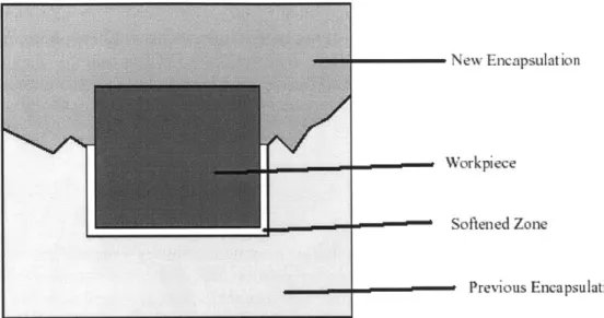
Sanjay Sarma* argues that this conceptual freezing of an object in space is possible. RFPE locates, secures, and supports a workpiece by encapsulating it with another material. This results in a cubical shape with the workpiece embedded inside the cube. Thus, instead of suspending the workpiece in air, RFPE suspends it in a metal medium. After the workpiece is initially encapsulated, it is cyclically machined and
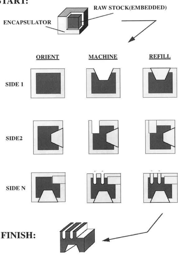
reencapsulated. The reencapsulation step allows the position of the workpiece to be stationary within a constant cubical structure. The material that the cube is formed of may change, but the geometry in which the workpiece is suspended does not. In this way, by keeping the workpiece stationary within the cube, one can always determine the part's location and orientation. Thus, the workpiece is conceptually frozen in space. This means that every time one places the part on the machine, one can choose the orientation that one wants that particular time. However, it is not necessary to relocate the part's references. Thus, by rotating the encapsulated workpiece, RFPE allows one to access all sides of the workpiece without having to relocate the part. Once the machining operations are completed, the encapsulation metal is melted away, leaving the part that was desired. Figure 7t describes the RFPE process pictorially.
* Sarma, S.E., A Methodologyfor Integrating CAD and CAM in Milling, Ph.D. Thesis, University of
California, Berkeley, 1995, p. 32.
Lee, E.C., Development of an Encapsulation Process for use in a Universal Automated Fixturing System, S.M. Thesis, Massachusetts Institute of Technology, 1999, p. 21.
START:
ENCAPSULATOR ORIENT SIDE 1 SIDE2 SIDE NFINISH:
RAW STOCK(EMBEDDED) MACHINE REFILL2.3. Capabilities of RFPE
RFPE is clearly the paradigm shift that was needed to achieve the four functional requirements of a fixture. Once the workpiece has been encapsulated, its position is constant with respect to the surface of the encapsulated workpiece. Thus, locating stability can be achieved. Furthermore, the regular geometry of the encapsulated workpiece permits the use of simple, precise fixtures, thus enabling deterministic workpiece location.
In addition, the RFPE process provides workholding capabilities superior to the current fixturing systems. The use of a phase change material to secure the workpiece means that no excessive force capable of deforming the workpiece can be applied during the
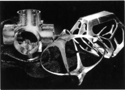
encapsulation process. Once the workpiece has been completely enclosed, all the surfaces of the part are supported. This not only ensures clamping stability but also allows the system to achieve total restraint. Thus, the encapsulated workpiece is totally located, supported, and secured. Therefore, RFPE has the potential to produce high quality components while minimizing the obstacles for both design and production. Figure 8* shows some sample parts produced with RFPE.
Figure 8: Sample parts produced with RFPE
* Lee, B.C., Development of an Encapsulation Process for use in a Universal Automated Fixturing System, S.M. Thesis, Massachusetts Institute of Technology, 1999, p. 35.
2.4.
Three Machining Strategies: 2D, 2%D, and 3D Milling
RFPE suspends a workpiece in space and allows access to all of its faces. However, having the encapsulated workpiece immobilize, support, and locate a part can result in a high level of complexity. Sarma* recognized that not all tasks warrant a high level of fixturing complexity. Therefore, in order to realize the RFPE concept with a level of complexity commensurate with the difficulty of the task, he developed three distinct machining strategies: 2D, 2 D, and 3D. The complexity permitted in the machining operations increases as one progresses from the 2D to the 3D Milling Strategy. It should be noted that, as one progresses from the 2D to the 3D milling strategy, the complexity permitted in the machining operations increases. Unfortunately, tied to this increase in
flexibility is an increase in the complexity and cost of the encapsulation equipment.
2.4.1. 2D Milling
2D milling is the simplest machining strategy. As Figure 9 shows, this machining
strategy allows 2 parallel faces of the workpiece to be accessed, using the other four faces to attach the workpiece to a fixturing device.
Figure 9: 2D Milling
This fixturing device provides the contact between the encapsulated workpiece and both the machine and the encapsulation system. Additionally, if one leaves this fixturing
device attached to the encapsulated workpiece for the duration of the machining and reencapsulation cycles, the fixturing device can take over the locational function from the encapsulated workpiece.
Sarma, S.E., A Methodologyfor Integrating CAD and CAM in Milling, Ph.D. Thesis, University of California, Berkeley, 1995, p. 46.
Lee, E.C., Development of an Encapsulation Process for use in a Universal Automated Fixturing
Since the fixturing device performs the locating function in 2D milling, the requirements for the encapsulated workpiece can be relaxed. Given that the surface of the
encapsulated workpiece is not used to reference the location of the part, this machining strategy requires neither precise surface finish nor exact dimensional repeatability. This significantly reduces the complexity of the encapsulation machine.
2.4.2. 2%D Milling
Often, more than two faces of a workpiece need to be accessed to produce a part. In these cases, 2D milling is clearly not applicable. However, only rarely does the
production of a part require all six faces of the encapsulated workpiece to be accessed. It is in these cases that that 21/2D milling can be exploited. This machining strategy is not as
simple as 2D milling, but one can still reap significant benefits from not having to access all six sides.
In 2/2D milling, a locating pallet covers one of the faces of the workpiece. As Figure 10* shows, this leaves five faces of the encapsulated workpiece free to be machined.
Figure 10: 2%D Milling
The locating pallet serves as the link between the encapsulated workpiece and both the machine tool and the encapsulation system. As in 2D milling, the fixture serves as the locational device, while the encapsulating material provides the immobilization and support required.
* Lee, B.C., Development of an Encapsulation Process for use in a Universal Automated Fixturing System, S.M. Thesis, Massachusetts Institute of Technology, 1999, p. 48.
2.4.3. 3D Milling
If the complexity of the part being produced requires all six sides of the workpiece to be
machined, the full power of RFPE needs to be unleashed. In this case, the 3D milling strategy, the most flexible of the machining strategies, is the most appropriate.
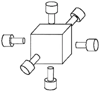
In this strategy, the encapsulated workpiece can be placed on the machine with any face up during any given portion of the machining cycle and can be turned as needed. Thus, as Figure 11* shows, this strategy permits access to the workpiece from all directions.
Figure 11: 3D Milling
The flexibility of the 3D milling strategy allows complex geometries, even those with thin cross-sections, to be generated with great precision.
In this strategy, the encapsulation is responsible for ensuring compliance with all four functional requirements of a fixture. This means that the encapsulation must not only retain and support the workpiece against machining forces, but it must also maintain the locational reference for the workpiece. Since the encapsulated workpiece may be placed in any orientation, variations in the encapsulation may affect the precision of the RFPE. This need for precision increases the rigor of the requirements for the encapsulation process and equipment.
* Lee, E.C., Development of an Encapsulation Process for use in a Universal Automated Fixturing System, S.M. Thesis, Massachusetts Institute of Technology, 1999, p. 48.
2.5.
Motivation
Clearly, the RFPE concept can be the lever that is needed to significantly improve the manufacturing process. It has the ability to satisfy-without compromise-all the functional requirements of a fixture, and yet, in conjunction with the three machining strategies, is flexible enough to work in a great variety of situations. The question then is whether this concept is actually feasible in reality.
Given the difficulties in modeling the RFPE process analytically, initially much of the work to prove the viability of the concept had to be done experimentally. Lee built an
encapsulation system at MIT, which has proved the viability of the process. However, as expected, it also left significant room for improvement.
RFPE can only advance once basic knowledge has been gathered in all the critical areas. Therein lies the motivation for this study: to establish a framework to understand RFPE, consolidate the existing knowledge, identify the critical factors that remain unexplored, determine the impact these factors have on the process, and thus develop the RFPE Process Parameter Map. This map will guide future designs and developments of the concept.
Chapter 3: Framework to Analyze and Develop RFPE
The goal of this study is to establish a foundation of knowledge on which the future work on the RFPE process can be based. Without this foundation, systematic improvement of the process cannot be achieved. The key to a solid foundation is a structured approach to the discovery and layout of the basic building blocks. Section 3.1 begins with a
description of this approach.
3.1.
The Building Blocks of a System
For any engineering problem, the information can be divided into three parts: the system, the inputs, and the outputs. For this study, the system in question is the RFPE concept. At this level of abstraction, the concept encompasses all aspects of the process and apparatus. The outputs are the values by which the system is judged. In particular, these are the attributes, or metrics, that determine how well the RFPE process meets its goals, including the functional requirements of fixturing and other aspects as esoteric as the floor space that needs to be dedicated to the device. The inputs, in turn, consist of the variables that can impact the quality of the process. These inputs can be further classified into environmental variables and parameters. Environmental variables are those factors, such as atmospheric pressure, that cannot easily be controlled. On the other hand, parameters are set either during the design of the apparatus or during the operation of the process.
3.2.
Design and Process Parameters
It is important to distinguish between design and process parameters. While both of these affect the operation of the system and may affect the same metrics, they represent very different things. Process parameters are indisputable properties of the concept, dictated
by the physical laws of nature. On the other hand, design parameters are the particular
characteristics selected for a particular implementation of the concept. Thus, any implementation of a system has the exact same process parameters as another implementation. However, two different implementations of a particular system are likely to have different design parameters.
Process parameters denote the conditions that can be theoretically varied for a given process. Depending on the sensitivity of the metrics to a particular parameter, the
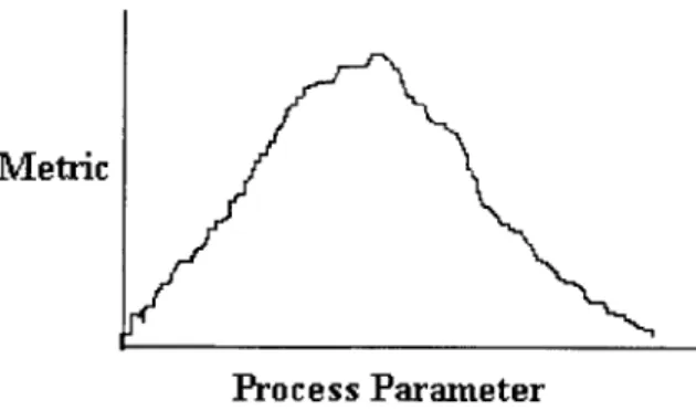
variation can impact the quality of the product produced. Thus, it is important to identify the process parameters for any system and investigate the relationship between each process parameter and each metric for the system. Figure 12 shows how the plot of a process parameter versus a metric can simplify the analysis of where the system should be run to maximize that particular metric.
Metric
Process Parameter
Figure 12: A plot of the relationship between each process parameter and each metric for a system facilitates an understanding of the
system characteristics
Theoretically, there are no limits to the extent to which a process parameter can be varied. However, in reality, the range of each process parameter is bounded by physical limitations. For example, if we consider two metrics that are affected by the same process parameter, we could imagine facing the situation depicted in Figure 13.
Metric #1 Metric #2
Metric
Process Parameter
Figure 13: Each process parameter typically impacts multiple metrics of the same system. Often, there is no optimum setting for the process parameter. Therefore, tradeoffs between the metrics are required.
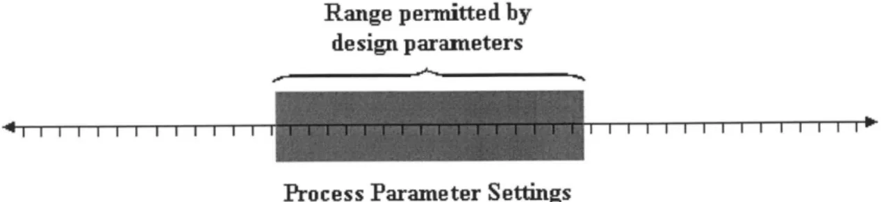
In this case, it would be impossible to select a setting for the process parameter without knowing the details of the situation so that we can make an informed tradeoff. Ideally, this means that in designing a system we would allow the user utmost flexibility to set the process parameter to whatever setting is best for the application at hand. However, in reality, we cannot feasibly build a machine that will allow all possible values of a given process parameter. Thus, as Figure 14 shows, for any given apparatus, there is a window within which the user can define the setting that is best for their particular application.
The boundaries of this window are defined by the choices made-implicitly or explicitly-during the equipment design process.
Range permitted by design parameters
Process Parameter Settings
Figure 14: Design parameters determine the range of each process parameter that is feasible for each implementation of the concept.
Design parameters are the characteristics of the device that determine the extent to which a piece of machinery can carry out its desired functionality. The particular design
parameters for a given system are selected based on the specific objectives of the
implementation being designed. These objectives guide the tradeoffs that are required by the often-contradictory nature of the process parameters, as shown in Figure 13.
Additionally, factors such as the cost of the process and the apparatus, production rate, and the quality specifications that the design has to meet also influence the choice of design parameters. Ultimately, the design parameters determine the extent to which a piece of machinery can carry out its desired functionality.
Ideally, design parameters are set such that they allow the end-user utmost flexibility in choosing the process parameter setting. In the process modeled by Figure 15, it is not possible to maximize both Metric #1 and Metric #2 simultaneously. Thus, the end user needs to select the setting that is best for the case at hand. Unfortunately, physical and cost limitations often do not allow for an apparatus that gives the user the ability to select a setting in the entire range. Thus, a particular implementation of the concept becomes a version of the concept optimized for a particular application.
Range permitted by design parameters
selected. Combination Metric
(a function of Metrics #1 & #2)
Metric #1
V
etric #2Process Parameter Figure 15:
diagram, the
For the particular implementation modeled in this choice was made to have the design parameters favor
Metric #1 slightly over Metric #2.
This means that, in order to design an optimal system, it is important to first determine the process parameters. With the process parameters defined, one can then investigate the effect that they have on each other and on the metrics. Then, with this basic
understanding in place, one can choose the applications that one wants to satisfy with one particular design and select the design parameters accordingly. In this way, systems satisfying the requirements can be built at a reasonable cost within a reasonable amount of time. For a different set of requirements, a slightly different implementation of the same process can be built.
3.3.
A Structured Approach to Developing the RFPE Process
The goal of this study is to develop a roadmap that will guide the future development of the RFPE concept. In order to do this, one must develop a means to systematically evaluate the importance of various factors. This evaluation can be accomplished through the identification of the critical metrics for the concept. By determining the process parameters that can potentially influence these metrics, one captures the core variables whose interrelationship will shape the quality of the product.
The next step in the journey lies in discovering the shape of these interrelationships. This can be done through a combination of literature review of similar processes,
mathematical analysis, and experimentation. The factors that have negligible impact can be discarded. Those that are crucial to the success of the concept will receive further attention to determine the concept's sensitivity to variation in these areas.
Chapter 4: Systematic Evaluation of Parameters and Metrics
This chapter establishes the foundation for a systematic evaluation of the criteria that may impact the RFPE concept. In particular, this chapter focuses on consolidatingknowledge, presenting parameters of known significance, and identifying parameters whose effect remains to be determined. Section 4.1 presents the metrics for the RFPE concept. Section 4.2 introduces the process parameters and summarizes both a literature review and the current research on how the process parameters impact the metrics.
Section 4.3 consolidates this information and presents the RFPE Process Parameter Map. Section 4.4 presents the next steps based on the current state of knowledge.
4.1. Metrics of the RFPE Process
The metrics selected to evaluate the performance of the RFPE process are measures of the quality of the encapsulated workpiece. These properties of the workpiece determine how well the process fulfills the functional requirements of fixturing. The metrics are divided into two categories: those that affect the precision of the process and those that
affect the integrity of the encapsulation.
The precision of the RFPE process is determined by the surface finish, porosity, shrinkage, and thermal drift of the encapsulated workpiece. These factors, in turn determine the minimal dimensional tolerance that one can achieve with this system. Additionally, the integrity of the encapsulation is affected by the rewelding strength as well as the presence of porosity. Sections 4.1.1 through 4.1.5 discuss these metrics.
4.1.1. Surface Finish
Surface finish refers to the relative roughness and flatness of the encapsulation surface. Since the surface of the encapsulation forms the load-bearing surface through which the encapsulated workpiece is fixtured, variations in surface finish can impact the
dimensional accuracy of the process.
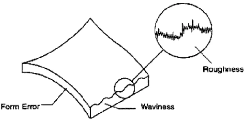
The surface finish can be characterized by the amount that the surface deviates from perfect flatness. As displayed in Figure 16,* there are three types of deviations: gross
deviation, surface waviness, and roughness. Gross deviation is called form error. Minor deviations can be called surface waviness or roughness. The distinction between
waviness and roughness is a function of the frequency of the undulations. For the
purpose of this study, the two will be considered as one single category and referred to as roughness.
Rougfroes
Formn Errr Waviness
Figure 16: A surface finish can be categorized by the amount that it deviates from a perfectly flat surface. There are three ways in which
this deviation occurs: form error, waviness, and roughness.
Form error can be measured with a coordinate measurement machine. Surface roughness can be measured with a profilometer. Profilometers are capable of greater resolution than the coordinate measurement machines and can provide a better characterization of the micro-scale features of the surface.
While these methods provide a fairly accurate way to characterize the flatness of a surface, this degree of precision is not always required. In many cases, the surface deformities do not affect a process as long as the roughness does not exceed a certain threshold value. In this instance, the use of a "go/no-go" gauge would be appropriate. An example of such a roughness gauge would be a surface roughness standard, which contains a variety of roughness samples that one can compare to the target surface.
4.1.2. Porosity
Porosity refers to the presence of voids in the encapsulation. These voids are formed either by shrinkage or by gases trapped during the molding process. Section 6.2
describes the porosity generating mechanisms more in-depth. The presence of porosity on the surface of the encapsulation forms defects that, in sufficient numbers, compromise the load-bearing capability of the encapsulation. The added deflection resulting from the compression of the defect-ridden surface impacts the accuracy of the process.
Furthermore, the presence of porosity inside the encapsulation can compromise the workholding ability of the encapsulation against the embedded workpiece. Finally, porosity in the encapsulation weakens the encapsulation since the voids reduce the amount of material available to withstand tensile and compressive loads.
The presence of porosity, both internal and external, has the potential to impact the quality of the RFPE process. The presence of voids in the encapsulation can be detected
by comparing the encapsulation density against the tin-bismuth density. The weight can
be obtained with a balance. The volume can be found by depositing the specimen into a graduated cylinder filled with water. The displaced volume of water will be equivalent to