Development of a Windows NT Real-Time Operating
System for NC Machine Control
by
Sokwoo Rhee
B.S., Mechanical Engineering Seoul National University, 1995
Submitted to the Department of Mechanical Engineering in Partial Fulfillment of the Requirements for the Degree of
Master of Science in Mechanical Engineering
at the
Massachusetts Institute of Technology
February 1997
@ 1997 Massachusetts Institute of Technology
All rights reserved
Signature of Author
Certified by
Department of Mechanical Engineering January 16, 1997
Haruhiko H. Asada Professor of Mechanical Engineering Thesis Supervisor Accepted by
Ain A. Sonin Chairman, Department Committee on Graduate Students
Development of a Windows NT Real-Time Operating System
for NC Machine Control
by Sokwoo Rhee
Submitted to the Department of Mechanical Engineering on January 16, 1997 in Partial Fulfillment of the Requirements for the Degree of Master of Science
in Mechanical Engineering
Abstract
A Windows NT real-time operating system for controlling multi-axis servo drives is presented in this thesis. It is guaranteed that the system can access I/0 devices within a fixed latency, i.e. 6 jls on a Pentium Pro 200MHz PC. While performing real-time motion control, the computer can access disk drives and perform GUI (Graphic User Interface) operation. To guarantee real-time operation, most time-critical computations and I/O operations are embedded in the kernel of the Windows operating system as a device driver, and processed at the level of Interrupt Service Routine. This real-time operating system allows us to eliminate the need for a dedicated coprocessor hardware board, often termed a Motion Control Card, that is designed to off-load the burden of real-time computation.
First the interrupt procedure in the Windows NT operating system is briefly described, and a way for guaranteeing real-time operations is presented. The time budget for interrupt services, data input and output, and control computations is analyzed. Based on the proposed interrupt handling technique and time budget analysis, a multi-axis AC servo motor control system is designed, built and tested. Not only velocity and position feedback but also current feedback, commutation, and PWM computations for multiple axes are performed all by software with a sampling interval of 100 ps. Experiments demonstrate that performing the real-time control does not significantly slow down the system in accessing disk drives and performing GUI operation. In addition, concept of network-based distributed control system was introduced and diskless PC network-based controller was examined as an promising component of the distributed system.
Thesis Supervisor: Haruhiko H. Asada Title : Professor of Mechanical Engineering
Acknowledgments
Most of all, I would like to express my best and sincere thanks to my thesis supervisor, Professor Haruhiko H. Asada, for his constant encouragement and guidance. His profound insight and splendid wide vision gave me a great chance to get into the world of new research directions. His valuable support and advice were the greatest factor that I could write this thesis. I also would like to express deep gratitude to my wonderful advisor, Booho Yang. He guided and helped me a lot in carrying out the project, and gave a great contribution to my research and thesis.
I also would like to express thanks to two visiting engineers, Keesang Lee and Youngjae Hur. Keesang gave me lots of valuable advice in experiments, and Youngjae helped me a lot with his affluent knowledge of electronics. He also helped me a lot with the drawings on this thesis.
I would like to thank to all my lab-mates in d'Arbeloff Laboratory who showed me sincere friendship and care. Also I would like to express deep thanks to my roommates, Chun Ho Kang and Sangjun Han, who made my life more energetic and enjoyable. I also would like to say thanks to all my friends in MIT.
Finally, I would like to express my best appreciation to my parents and my sister, Eun-jung Rhee, who have been watching me with great love. Their love and care have been the main source of energy that encouraged me through my life.
Contents
1. Introduction 9
2. Basic Structure of PC-based Controller using Windows NT Real Time Operating
System 11
3. Windows NT Real Time Operating System 13
3.1 Windows NT as a Real Time Operating System 13
3.1.1 Pentium Pro CPU 13
3.1.2 Advantages of adopting Windows NT as a base of real time operating system (Comparison
with Windows 95) 14
3.1.2.1 Similar Points 14
3.1.2.2 Different Points 15
3.1.2.2.1 Windows NT 15
3.1.2.2.2 Windows 95 16
3.1.2.3 Which is better for our purpose? 17
3.2 Basic Concept 18
3.2.1 Use of Interrupt for Real Time Operation on Windows NT 18
3.2.2 What is the problem in implementing real time control in Windows NT? 20
3.3 Implementation 22
3.3.1 Device Driver on Windows NT 22
3.3.2 Interrupt Handling 24
3.4 Evaluation of Windows NT as a Real Time Operating System 26
3.4.1 Determinism 26
3.4.2 Responsiveness (Interrupt latency measurement) 26
3.4.3 User Control 28
3.4.4 Reliability 29
3.4.5 Fail-Soft Operation 29
4. Networking 31
5. NC Machine control using Windows NT Real Time Operating System 33
5.1 Virtual Motion Control Card (VMC) 33
5.1.2 position and Velocity Feedback Feedforward Compensation, Trajectory Interpolation, and Commutation : (Interrupt Service Routine with Priority Level 4 (or 5)) 35 5.1.3 Parameter Tuning, Adaptive and Learning Control (Deferred Procedure Calls and User Mode
Application Program Level) 36
5.1.4 Trajectory Data Update (User Mode Application Program Level) 36
5.2 Concept of Digital AC Servo 38
5.2.1 Traditional Method -Structure of AC Servo Control by Hardware 38
5.2.1.1 Sine wave generation circuit 38
5.2.1.2 DC-SIN conversion circuit 39
5.2.1.3 PWM Generation Circuit 39
5.2.2 New Method -PWM Generation by Software 40
5.3 Experimental Setup and Evaluation 42
5.3.1 Experimental setup 42
5.3.2 Influence of keyboard and mouse 46
5.3.3 Sample Time Budget 48
5.3.4 Performance 50
5.3.4.1 Feedback Performance Evaluation 52
5.4 Advanced Full-Digital AC Servo 54
5.4.1 Commutation and Current Feedback by Software 54
5.4.2 I/O0 Interface for Advanced Full-Digital AC Servo 55
5.4.3 Select of Power Block for Full Digital AC Servo System 56
5.4.3.1 Dead Time Generation 58
5.4.3.2 No velocity or position loops, and not expensive 59
5.5 Use of network on NC machines 59
5.5.1 Need for Network on NC Machines 59
5.5.2 Network-based, Distributed NC Machine System 60
5.5.3 Diskless PC-based NC Machines for Factory Automation 60
6. Conclusion and Future Work 63
List of Figures and Tables
Figure 1. Diagram of Basic PC-based Controller 11
Figure 2. Layered Operating System Structure of Windows NT 16
Figure 3. Relations of DOS and Windows 17
Figure 4. Use of Interrupt in Real Time Control 21
Figure 5. Structure Diagram of Simple NT Driver 23
Figure 6. Basic Structure of Interrupt Handling on Windows NT 25
Figure 7. Interrupt Latency Measurement 27
Figure 8. Distributed Control System based on Network 32
Figure 9. Traditional Motion Control Card 33
Figure 10. Basic Structure of Windows NT based Real Time Control System 34
Figure 11. Conceptual Timing Chart 37
Figure 12. Block Diagram of Brushless Servomotor Control System 39
Figure 13. Pulse Width Modulation 40
Figure 14. Brushless Servomotor Control System Diagram with PWM by Counter 41
Figure 15. Overview of Experimental Setup 42
Figure 16. A Closer View of Amplifier Unit 43
Figure 17. Structure Diagram of Windows NT based Motion Control System 43 Figure 18. Graphic Interface for the Real Time Control Operation 44
Figure 19. Control Main Panel 45
Figure 20. Trajectory Generation/Selection Panel with a Dialog Box for Online Trajectory Selection 45 Figure 21. Influence of Keyboard on Position Error 46 Figure 22. Influence of Serial Mouse on Position Error 47 Figure 23. Influence of PS/2 Mouse on Position Error 48 Figure 24. Reference Input and Actual Position of XY Table Movement 50 Figure 25. Velocity and Current Value of XY Table Movement 51 Figure 26. Overall Control Algorithm of Experimental XY-Table Setup 51 Figure 27. Response to Step Velocity Input (Velocity and Current) 52 Figure 28. Response to Step Position Input (Reference Input and Actual Position) 53 Figure 29. Response to Step Position Input (Velocity and Current) 53
Figure 30. Advanced Full-Digital AC Servo 54
Figure 31. Block Diagram of I/O Interface Board for Advanced Full-Digital AC Servo 56 Figure 32. A/D Converter Board designed for Advanced Full-Digital AC Servo 57
Figure 34. Remoteboot, Distributed Control System 61
Table 1. Interrupt Priority Levels of PC 25
1. Introduction
There is an increasing need for PC based numerical control in the machine tool and robotics industries. PC's have potentials to provide low-cost, user-friendly, open architecture controllers, which would replace the traditional dedicated controllers exclusively provided by a few venders of NC controllers. Advanced PC operating systems provide a powerful graphic user interface and allow users to easily incorporate isolated machines into a network based system. Moreover, a variety of application software developed for PC's can be used as well. The problem with GUI operating systems, however, is that real-time control and time-critical operations can hardly be performed under the advanced GUI operating systems. The current practice is to use dedicated motion control cards with DSP chips to off-load the burden of real-time computation and interrupt handling. Dedicated motion control cards not only limit the flexibility of the system but also increase the cost : the total cost of a PC and motion control cards is often more expensive or comparable to that of the traditional NC controllers.
The rapid progress of CPU's computing power may eliminate the need for dedicated motion control cards and replace them by software alone. Real-time operating systems, especially, are playing more important roles for complex real-time control applications. A real-time operating system in the feedback loop of such a control system must respond to periodic external interrupts consistently within a certain time limit called "hard deadline"[1]. If the delay in the operating system exceeds the hard deadline, the system behaves unexpectedly and may cause instability. A similar phenomenon also can be observed if the interrupt sampling in the feedback loop is fluctuated. To meet the deadline and the temporal consistency requirements for time-critical applications, the real-time operating system must have a microscopic, consistent interrupt latency.
In the past years, many algorithms have been developed to handle the external interrupts and the computation under the above timing-related constraints. To name a few, the worst case execution time estimate approach [2, 3, 4], the queuing spin lock algorithm [5, 6], and the integrated inter-process communication and scheduling scheme
[7] are recent results. These approaches have already been implemented and tested on the high-end platforms such as UNIX workstations. However, in spite of the recent explosive improvement of performance and reliability of PC's, available real-time operating systems for PC's are not fast nor reliable enough for time-critical control applications. Also, the lack of GUI and the inconsistency with PC's de facto OS such as Windows prevent these real-time operating systems from being widely used in the control industries. If the high-performance real-time functionality is appended to a general-purpose OS such as Windows, the current practice of the real-time control industries would be changed.
The goal of this thesis is to develop software for handling interrupts and performing time-critical computations for NC machine control under the Windows NT (version 4.0) operating system, and to combine it with strong networking capability of Windows NT to maximize the performance of NC machines. The comparison of Windows NT and Windows 95 is done to show that Windows NT is the better solution for real time operation on PC. Windows NT has the capability to provide fast response time, but is not deterministic under the preemptive multi-tasking architecture [8], and, therefore, is not suited for time-critical real-time operations such as the current feedback of AC servo motors with 50 gs to 100 gs sampling rate. But yet Windows NT is a stable 32-bit operating system with powerful networking and graphic user interface capabilities. It is expected that adding the real-time OS feature to Windows NT will provide quite a useful tool for the robotics and NC machines community and beyond. In addition to that, the implementation of the fully software-based digital AC servo for motion control is discussed. With this AC servo control system, it is expected that we can replace lots of dedicated hardware with simple and inexpensive software for AC motor driving. Finally, Influence of networking capability on our system for NC machines is observed. The networking of many individual NC machines is critical in a large-scaled FA system. Many NC machines (or industrial robots) can be tied up through networking and controlled by a single central server with small number of men. Also, a factory composed of a huge number of independent machines can be effectively synchronized and integrated through networking, which will make the factory automation more efficient and faster.
2. Basic Structure of PC-based Controller using Windows NT Real Time
Operating System
One of the principle directions of this research is to reduce the cost of the motion controller. This is also the main reason that we have to use PC for motion control. To accomplish this policy, it is natural that we should minimize the number of additional hardware attached on PC. In this sense, we have to design our controller so that we don't have to use any DSP board which is quite expensive. Sometimes the costs of some DSP boards are almost close to the cost of PC itself. To remove DSP board, we should control almost everything by PC using only the really basic additional hardware such as D/A converters, A/D converters, and counter / timers. This means that the CPU has to do almost everything related to real time control, including sampling in a specified rate. Actually, this is where the CPU interrupt is used for. To do sampling in an accurate interval, external counter / timer board is necessary as a signal generator. The diagram for the basic structure of PC-based controller is shown on Figure 1.
The control algorithm is Application
embedded in the device driver. Pr•onam CPU / GUI Operating System
ice
ier
ut
Timer is used here as a clock generator. This timer generates pulses or square waves by accurate interval. The signal output of the timer is connected to the IRQ (Interrupt ReQuest) line of PC. When the CPU receives the interrupt request signal, it jumps to the interrupt service program which is already built in. In this interrupt routine, CPU takes sampled data from the A/D converter connected to the sensor, (In case of position and velocity control, this "sensor" should be encoder which is connected to motor, and an encoder counter should be used in place of A/D converter.) Based on this sampled data, control algorithm calculates the next control input value what should be sent to D/A converter, which is also connected to amplifier (motor driver) and ultimately drives the servo motor.
In our system, the very first task to be done is to decide what kind of operating system and CPU we should use. In terms of CPU, Intel has the Pentium Pro (code name P6) on the market. This is the advanced version of Pentium processor, and it employed several more advanced technologies that were not shown in Pentium processor. About operating system, we have two candidates. One is Windows NT and the other is Windows
95. (Windows 3.1 was ruled out because it is basically old-fashioned version among the Windows families.) Now we will go through the new features of Pentium Pro first, and after that, we will look into the features of Windows 95 and Windows NT, and decide which operating system is better for our purpose.
3. Windows NT Real Time Operating System
3.1 Windows NT as a Real Time Operating System
3.1.1 Pentium Pro CPU
N Superscalar Structure
Traditional processors used in computers have been all CISC (Complex Instruction Set Computer) chips. This kind of chips basically execute one command at a time. But RISC (Restricted Instruction Set Computer) chips are different. They are basically designed so that they can execute multiple command simultaneously. This technique is called "Superscalar." Though this technique was originally used in RISC chips, Pentium Pro adopted this technology in it. (This is one of the reasons that some people say that Pentium Pro is located between RISC chips and CISC chips.) As the result, Pentium Pro can execute multiple commands at once, which makes its performance much better than previous chips based on the traditional CISC technology.
* Multiple Branch Prediction and Data Flow Analysis
Simultaneous execution of multiple commands leaves a big problem. The commands in a program is basically designed to be executed sequentially. The problem occurs when a command should be executed based on the data generated by previous commands. To reduce this kind of data dependency as much as possible, a few techniques are used in Pentium Pro, for example, multiple branch prediction and data flow analysis.
"Multiple branch prediction" is the function that predicts branching of a program beforehand based on the previous experiences stored in branch target buffer in CPU. If a CPU can predict the branching of the commands flow, it is possible to execute a certain command together with the following commands at once. In other words, this helps remove the problems that can occur when using superscalar technique.
"Data flow analysis" is the term that describes the operation that rearranges the sequence of commands, so that the commands can be executed as independently as possible. This function also helps superscalar engine in Pentium Pro run without any bubble.
0 Internal L2 Cache
The Pentium Pro is actually composed of two chips in a package. One is the chip that really does the computation work, and the other is the cache memory chip. Of course, most of the previous chips already have had internal cache in it. (This is called L1 cache, or internal cache.) But as this internal cache is not enough to get satisfactory performance, almost all the computers have another cache memory built on outside of CPU. (This is called L2 cache, or external cache.) In Pentium Pro, this L2 cache is already built in itself. This makes the cache system work much faster, removing what is called "bottle neck phenomenon."
a Best Performance with 32-bit Operating System
When executing 32-bit commands, Pentium Pro does it in a fast and optimized way. But with 16-bit commands, this CPU changes them into 32-bit commands first, and then execute them, and this process takes quite a long time. So if we run 16-bit commands on Pentium Pro, it is sometimes slower than that of Pentium processor. So, basically Pentium Pro goes well with 32-bit operating system.
3.1.2 Advantages of adopting Windows NT as a base of real time operating
system (Comparison with Windows 95)
As was mentioned above, the first candidates for our base operating system are Windows NT and Windows 95. Although these two operating systems seem to be almost similar to each other at the first glance, there are quite a few different points inside. To choose the best operating system for our purpose, it is inevitable to compare their good points and bad points. After that, we can make a smart decision about which one is better.
3.1.2.1 Similar Points
" Basically 32 bit operating system.
a
None of them needs MS-DOS before the booting (which was the case of Windows 3.1)." Support preemptive multitasking.
3.1.2.2 Different Points
3.1.2.2.1 Windows NT
[ Windows NT was originally built focusing on robustness in multi-tasking, rather than
compatibility with previous versions of Windows.
* Windows NT also focuses on portability, which makes it easy to port Windows NT to many different CPU's including RISC chips, due to the fact that major parts of Windows NT were written in C or C++, and the amount of the parts written in assembly language wasminimized.
" Windows NT allows us to use multi-processors, which can increase the speed and
efficiency with same amount of given tasks if properly programmed.
" Windows NT is a true 32 bit operating system, with almost all the kernels and user
modules built in 32 bit commands. This point is important that it can reduce the time delay because Windows NT does not do "flat thunking (especially "thunking down") in the programs originally built for 32 bit operation.
* Windows NT supports more affluent Win32 API's than Windows 95, which helps the full 32 bit programming.
" Windows NT supports many different types of file systems including NTFS, which
was designed with consideration of recoverabilityand security.
* Windows NT does not work with real-mode device drivers, which means that it does not allow direct access to hardware. Though sometimes this makes programmers who deals with hardware control feel difficult, it can be said to be a good point in view of robustness.
" Windows NT cannot run DOS device drivers, which also makes the programmers who
are already accustomed to DOS environment feel hard.
" Windows NT has the apparent tendency to run faster with more memory. Although
Windows NT seems slow compared with Windows 95 with a small memory, its speed goes up dramatically with additional memory.
* The memory occupied by each program is strictly independent to each other. This is a very good aspect for system stability in multi-tasking or multi-processing.
" Windows NT has a layered operating system structure shown on Figure 2. (Actually,
this kind of structure is possessed by almost all kinds of operating systems except the simplest ones. Actually, Windows 95 can be said to be a combination of DOS and advanced version of Windows 3.1. So Windows 95 still has somewhat primitive structure in it. But as Windows NT was designed very differently from Windows 3.1 or before, it has a complete layered structure like UNIX. It is also important that Windows NT is originally built considering netweking from the beginning.
* More user-friendly interface of Windows 95 was also adopted in Windows NT version 4.0.
Mode
Mode
Figure 2. Layered Operating System Structure of Windows NT
3.1.2.2.2 Windows 95
* Windows 95 was originally designed focusing on compatibility, rather than reliability.
" Windows 95 requires smaller PC resource requirements than Windows NT even though its difference is not significant.
" Windows 95 is basically designed to be perfectly compatible with Windows 3.1. So,
almost all the software previously built under Windows 3.1 environment runs also well under Windows 95.
" The structure of device drivers for communicating with external hardware is similar to
that of Windows 3.1. This is actually the main point that attracts the programmers who are already used to Windows 3.1 hardware control programs to choose Windows 95
rather than Windows NT.
" Windows 95 does not support multi-processors.
" Windows 95 uses lots of down-thunking, especially in USER.DLL module, which
makes some time delay in running the programs built with 32 bit commands.
* DOS is embedded in Windows 95. Windows does not lie on DOS any more, but they are in parallel relation, as shown onFigure 3.
<IX38+IS+
bw3.1>
<Windows95>
Wnch%
Figure 3. Relations of DOS and Windows
3.1.2.3 Which is better for our purpose?
Windows NT is thought to be better, considering the following aspects.
" Windows NT provides a good robust environment for multi-tasking, since it was
designed focusing on robustness in multi-tasking.
* As Windows NT allows us to use multiprocessors, for example dual Pentium Pro, it is better from the viewpoint of expandability in the future.
* Considering the trend that is going to the 32 bit programming, Windows NT is better in that it was fully developed for 32 bit programs. We can also reduce the time delay caused by down-thunking in case that we use Windows 95 with the 32 bit programs. * Windows NT is originally built on client-server model, which means that Windows NT
is basically designed in consideration of networking. As we may use networking in the future development, networking capability is an important factor.
* In terms of users interface, it was true that Windows 95 was better than Windows NT (version 3.51). But as Windows NT version 4.0 also adopted the user interface of Windows 95, which is new and more user-friendly, it is not a problem any more.
It is thought to be better to use Windows NT, rather than Windows 95, in many aspects mentioned above. Windows NT has many good points that are necessary for our purpose, and the combination of Windows NT and Pentium Pro is expected to give out the best performance we need. Programming should also be done on the base of full consideration of the typical features of these CPU and operating system to get the best performance and accuracy in robot control.
Unlike DOS, Windows NT basically prohibits any direct access to the external hardware attached to PC, and this is what makes interrupt handling on Windows NT difficult. In the next chapter, the process and technique of interrupt handling in Windows NT will be explained.
3.2 Basic Concept
3.2.1 Use of Interrupt for Real Time Operation on Windows NT
In real time control, using the interrupt operation is essential. It is inevitable to guarantee accurate sampling rate in PC based control. Actually most of the control algorithm is coded in the interrupt routine, no matter its operating system is DOS or Windows NT. So, what the main program does is confined to very simple and relatively trivial job - displaying the results or variables on the screen, for example, drawing graphs for easy understanding of the users.
Windows NT as that on DOS or other real time control oriented operating system. It is basically due to the fact that Windows NT is designed to be independent of the hardware. In DOS, hardware is almost directly open to the programmer so that it is very simple to access hardware directly, and as the result, it is not so difficult to build a interrupt handling routine if a programmer knows a little about the hardware. The interrupt of PC is controlled by 8259A Programmable Interrupt Controller. Thus, in DOS, there is no problem in handling interrupts if we just know how this interrupt controller chip works and how to program it. But in Windows NT, the registers of this chip is not reachable to programmer. So we have to handle interrupt using the standard way that Microsoft provides.
In principle, giving the right to directly control interrupt to the programmers is against the basic policy of Windows NT. Windows NT is a preemptive multi-tasking system, which implies that all of the running applications should be under the control of operating system. If any application is free to use CPU interrupt, it is already not a perfect preemptive multi-tasking system. But, as no computer can do without minimum external hardware, such as keyboard, mouse or printer, there should be some ways to handle interrupts open to the programmers. (Keyboard and mouse cannot be realized without interrupts.)
In Windows NT, or in any other Windows systems, the contact with peripherals is done by device drivers. Of course, interrupt handling is done as a part of device driver. There are two kinds of device drivers in Windows NT. One is kernel mode device driver, and the other is user mode device driver. To obtain the full control of hardware, we should use kernel mode drivers. "Kernel" can be thought of as the base of the operating systems, which means its distance to hardware is closer than that of user mode which the application software runs in. The problem is that, in kernel mode programming, we cannot use the standard C run time libraries which is familiar to application programmers. This is the main factor that makes programmers hesitate to get into the Windows system programming.
The most standard and safe method of developing device drivers is using DDK (Device Driver Development Kits) produced by Microsoft. This kit provides lots of
functions which can be used for programming device driver in kernel mode. It is not impossible to make device drivers in standard C or C++ compilers such as Visual C++ 4.0, as long as they generate fully 32 bit code. But using DDK has lots of benefits that cannot be obtained from standard compilers.
We will go through the basic structures of device drivers of Windows NT, and we will show how interrupt can be handled in device drivers. We will also show some essential things that should be considered in developing real time control software on Windows NT device drivers, which is very important.
3.2.2 What is the problem in implementing real time control in Windows
NT?
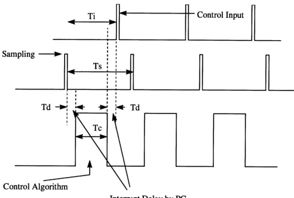
Besides the difficulty of coding external hardware control program, there is a very critical issue in using Windows family as an operating system for real time control. This problem is shown on Figure 4.
When an interrupt request comes in from the external hardware such as counter or signal generator, there is always some time delay before the specified interrupt routine starts running. This is because it takes some time for the processor to carry out some preparing works before the interrupt routine runs. For example, all the values of registers in CPU must be stored in a safe place such as stack. These values are returned to their original position when the interrupts routine finishes its work, so that CPU can resume the previous work without any problem. There are also several more tasks that CPU has to do beforehand. In addition to this, the same amount of time as interrupt latency is needed for CPU to finish the interrupt routine and to go back to original work. In this delay, works such as carrying back the original values of registers stored in a safe place are done. So actual loss of time caused by interrupt latency is 2 times of Td.
To guarantee stable accomplishment of recurrent interrupts, the interrupt running periods must not overlap each other. For this, the following inequality should be satisfied.
Control Input
Interrupt Delay by PC
Figure 4. Use of Interrupt in Real Time Control
Ts : Sampling interval.
Ti : Total time necessary for interrupt routine to be executed once.
Td : Interrupt latency (Interrupt delay : Time from the point when interrupt
is requested by external counter to the point when interrupt routine starts running.) Tc : Time required for control algorithm to do its work.
Ti (= Tc + 2 * Td) < Ts
In traditional cases, the problem on this inequality is always Tc. As the control algorithm becomes more complicated, it takes more time in computing and Tc becomes larger naturally. But also as control algorithm becomes more complicated and sophisticated, it is also true that it's better to achieve small Ts, which means high sampling rate. Therefore, optimization of Tc and Ts always becomes critical issue in real time control using interrupts. But as Ts and Tc has been relatively much larger than Td in
San
Col
traditional simple feedback, Td has seldom been any problem and has been almost neglected. But in our approach, Td also becomes critical. There are two factors which changes the "normal" situation here.
E As we are planning to achieve higher sampling rate than before, Ts should become
smaller than ever. If Ts becomes small to a certain point, Td cannot be neglected, because the order of magnitude of Ts can become close to that of Td.
* The interrupt latency under Windows family is known to be much longer than that under DOS. This is because the interrupt routine calling process under Windows is not so simple as that under DOS. Some books say the former takes more than 10 times longer than the latter. If this turns out to be true, it can even be a major problem in satisfying the above inequality.
So, we have to measure the Td first. If we can verify that it is still far much smaller than required Ti, then it's OK. But if it turns out to be too large to satisfy the above inequality, then we have to consider adopting some other operating systems. So the first critical issue is measuring Td, and to do this, we have to know how to use interrupts on our desired operating system, Windows NT.
3.3 Implementation
3.3.1 Device Driver on Windows NT
In Windows NT and any other Windows system, interactions with peripheral devices are handled by so-called Device Drivers. Our objective is to develop a special device driver to be involved in the "Kernerl" of Windows NT operating system so that a group of I/O devices necessary for motion control can be accessed and run in real time.
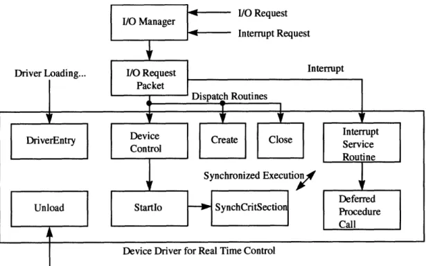
The basic structure of NT drivers is shown on Figure 5. As the I/O Manager and I/O Stack Location are already embedded in Windows NT kernel, the things we actually should build are DriverEntry routine, Unload routine, Dispatch routine, Startlo routine, Interrupt Service Routine (ISR), and Deferred Procedure Call (DPC) routine for a simplest NT driver.
Device Driver for Real Time Control Driver Unloading...
Figure 5. Structure Diagram of Simple NT Driver
" DriverEntry : When an NT driver is loaded, its DriverEntry routine is called with a
pointer to the driver object. The DriverEntry routine sets one or more Dispatch entry points in the I/O Stack Location in IRP (I/O Request Packet). When any I/0 request comes in, the I/O Manager refers to I/O Stack Location and routes the IRP to the appropriate Dispatch routine that supplies the specified drive. The DriverEntry routine sets the entry points of Startlo and Unload routine. This routine also connects the device driver to IRQ (Interrupt ReQuest) line.
" Unload : When an NT driver is unloaded, its Unload routine is called, and this routine
does what is required in unloading the driver.
* Dispatch routine : Every driver should have at least one Dispatch routine to do desired I/O operation. When an I/O request for a driver comes in, CPU jumps to the appropriate Dispatch routine. This routine usually calls I/O support routine to pass on each IRP with valid arguments to the Startlo routine.
[ Startlo routine : This is the routine that actually starts the requested I/O operation on a particular device.
" Interrupt Service Routine (ISR) : When an interrupt is requested, CPU jumps to a
specified Interrupt Service Routine. In principle, this routine should execute as quickly as possible, doing only what is necessary at the point. It is because of the fact that ISR runs at DIRQL (Device Interrupt ReQuest Level) which prevents other threads from running, and totally occupies CPU. It is basically against the fundamental policy of Windows NT -preemptive multitasking. Usually, the ISR does as little I/O operation as it can, and queue a Deferred Procedure Call (DPC) to complete the interrupt-driven I/O operation at a lower interrupt request level.
* Deferred Procedure Call (DPC) : This routine is primarily used when an ISR needs to perform more work, but should do so at a lower IRQL than one in which ISR runs. The main reason this routine is needed is that it is better to finish ISR as soon as possible to keep the overall system response timefast enough.
3.3.2 Interrupt Handling
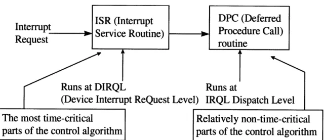
Figure 6 shows the procedure for handling interrupts under the Windows NT environment. When an interrupt request comes in, the CPU jumps to special routines, called Interrupt Service Routine (ISR) and Deferred Procedure Call (DPC). In ISR, all interrupt requests coming from other devices having lower priority levels are masked off, whereas in DPC no interrupt is masked off. Namely, any other interrupt can be accepted during the DPC execution, even though the interrupt requested has a lower priority level than that of the one currently being processed. The preemptive multitasking policy of Windows NT requests that only the time-critical tasks must be performed in ISR so that the CPU may not be occupied by a particular device for a long time. After leaving the ISR soon, most of the tasks that are not time-critical are performed in DPC.
Table I shows the interrupt priority levels assigned to each device in the Windows NT system. Levels 3 and 4 are assigned to a user's devices. Note that a keyboard and a certain type of mouse have higher priority levels than the user devices.
To guarantee the exact sampling interval for real time control, a counter/timer board is used to request interrupts to the CPU. We generate two square waves with different intervals for two separate interrupt procedures. The ISRs in the device driver are
programmed to carry out the feedback loops according to the specified control algorithm.
Interrupt
ISR (Interrup
tRequest
Service Routine)
Runs at DIRQL
R
(Device Interrupt ReQuest Level) I
The most time-critical
parts of the control algorithm
DPC (Deferred
Procedure Call)
routine
uns at
RQL Dispatch Level
Relatively non-time-critical
parts of the control algorithm
Figure 6. Basic Structure of Interrupt Handling on Windows NT
Interrupt Priority Level Device Name
0 (highest) System Timer
1 Keyboard
2 cascaded from slave PIC
3 COM 2 *
4 COM 1*
5 LPT 2 *
6 Floppy Disk Controller
7 LPT 1 *
8 Real Time Clock
9 Redirection to IRQ 2
10 Reserved *
11 Reserved *
12 PS/2 Mouse
13 Reserved (Co-processor) *
14 Hard Disk Controller
15 (lowest) Hard Disk Controller
*: IRQ lines that are used by non-critical devices for basic operation of PC. Thus, this lines are
usually available to the users.
Table 1. Interrupt Priority Levels of PC
3.4 Evaluation of Windows NT as a Real Time Operating System
3.4.1 Determinism
An operating system is deterministic to the extent that it performs operations at fixed, predetermined times or within predetermined time intervals. When multiple processes are competing for resources and processor time, no system will be fully deterministic. In a real-time operating system, process requests for service are dictated by external events and timings. The extent to which an operating system can deterministically satisfy requests depends, first, on the speed with which it can respond to interrupts and, second, on whether the system has sufficient capacity to handle all requests within the required time. One useful measurement of the ability of an operating system to function deterministically is the maximum delay from the point of the arrival of a high-priority device interrupt request to when servicing begins. In nonreal-time operating systems, this delay may be in the range of tens to hundreds of milliseconds, whereas in real time operating systems that delay may be of a few microseconds or milliseconds [9].
The Windows NT is basically not a real time operating system. Naturally it is not so deterministic under preemptive multitasking environment, on which most of user level application programs run. Therefore it is obvious that we can't use application programs as a base for real time purpose. But as we are running real time tasks with the help of interrupt, the deterministic character of Windows NT is not so bad, even though it cannot be said to be excellent. This property can be also proved with the experiment described on the following section, as it proves of good responsiveness of Windows NT operating system.
3.4.2 Responsiveness (Interrupt latency measurement)
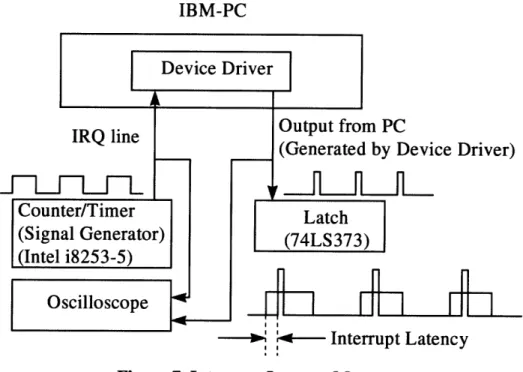
Interrupt latency can be one of the most reliable criteria at determining the responsiveness of an operating system. (As was stated above, it is also a good criteria to see whether an operating system is deterministic or not.) To measure the interrupt latency on Windows NT, a simple circuit was designed. Its structural diagram is shown on Figure 7.
IBM-PC Device Driver IRQ line
i~-h~hi-h
Counter/Timer (Signal Generator) (Intel i8253-5) Oscilloscope Output from PC(Generated by Device Driver)
Latch (74LS373)
S Interrupt Latency
Figure 7. Interrupt Latency Measurement
As a signal generator, a counter/timer chip was used, and the ISR in the device driver is programmed to give out an output signal from PC. We can measure the time difference between these two signals, which is the interrupt latency, Tdon Figure 4.
The interrupt latency experiment results obtained are shown onTable 2.
Type of CPU \ OS DOS Windows NT
386DX - 33 MHz 30 Is ± 15 Is N/A
Pentium 133 MHz 6 gs ± 1 is 9 ts
Pentium Pro 200 MHz 5 is 6 ts
Table 2. Interrupt Latency Measurement Results
As is shown, in DOS environment, there are quite much fluctuations on interrupt latency, which doesn't seem to be good for periodical sampling. But in Windows NT, fluctuation almost disappears. It seems that it is because Windows NT is scheduling all the threads already, so that CPU is always ready to accept interrupt request without any confusion.
Interrupt latency in Windows NT is longer than that in DOS, as expected. But it is
not like 10 times or 20 times which we have been worried about. As the fastest sampling rate which will be used in current feedback is expected to be around 10 kHz (Ts on Figure 4 equals 100 gs.), interrupt latency of 6 gs in Windows NT with Pentium Pro 200 MHz will not be a significant problem. So, it is verified that using Windows NT as an operating system for real time control seems to be all right in terms of the interrupt latency problem.
3.4.3 User Control
User control is generally much broader in a real time operating system than in ordinary operating systems. In a typical nonreal time operating system, the user either has no control over the scheduling function of the operating system or can only provide broad guidance such as grouping users into more than one priority class. In a real time operating system, however, it is essential to allow the user fine-grained control over task priority. The user should be able to distinguish between hard and soft tasks and to specify relative priorities within each class. A real time system will also allow the user to specify such characteristics as the use of paging or process swapping, what processes must always be resident in main memory, what disk transfer algorithms are to be used, what rights the processes in various priority bands have, and so on [9].
Windows NT basically does not allow the user to specify the priorities of individual user level application tasks. Even if there are several tricky ways for the programmers to do this, on the contrary, Windows NT strongly defend itself from any effort of users to get into its own scheduling jobs. So if we only think about the user level applications, the user controllability of Windows NT is far behind the need for real time performance. But as our system carries out the most of its time-critical works in the interrupt service routines, we can specify the priorities of the tasks according to the predefined interrupt request priority levels of the CPU. In addition, Windows NT supports multitasking with inter-process communication tools such as semaphores and events. But it is still impossible for the user to specify use of paging, process swapping, and so on. As the consequence, the user controllability of Windows NT cannot be said to be satisfactory, but still enough for general real time tasks if we use the interrupt capacity.
3.4.4 Reliability
As real time operating system usually controls heavy and dangerous machines, reliability is typically far more important for real time operating system than nonreal time operating system. The Windows NT was designed to run each application in their own processes and cannot read or write outside of their own address space. The operating system data is isolated from applications. Applications interact with the kernel indirectly using well-defined user-mode APIs. Thus it is almost impossible that Windows NT stops due to the errors caused by user level applications, and this fact shows the good reliability of this operating system. But still, kernel mode drivers might cause Windows NT to stop during critical operations. So the machine that is controlled by the Windows NT operating system should be equipped with some emergency shutdown devices to prevent any disastrous accidents. Instead, Windows NT has a good functionality for failure analysis, which will eventually reduce the unexpected shutdown of the operating system.
3.4.5 Fail-Soft Operation
Fail-soft operation is a characteristic that refers to the ability of a system to fail in such a way as to preserve as much capability and data as possible. For example, a typical UNIX system, when it detects a corruption of data within kernel, issues a failure message on the system console, dumps the memory contents to disk for later failure analysis, and terminates execution of the system. In contrast, a real time system will attempts to either correct the problem or minimize its effects while continuing to run. Typically, the system will notify a user or user process that it should attempt corrective action and then continue operation perhaps at a reduced level of service. In the event a shutdown is necessary, an attempt is made to maintain file and data consistency [9].
Windows NT is basically a kind of UNIX in its architecture. As the result it behaves similar to UNIX when it detects any problem or corruption - dumping the memory into a file in hard disk, and terminate the system or restart the whole system. From the viewpoint of later failure analysis, this feature is good for system maintenance, even if it doesn't have such functionality as continuing the process in spite of error detection of kernel, which is one of the necessary functions of real time operating system.
(Windows NT never stops with any failure of user level application. Only kernel level failure can stop Windows NT.) For recovery options, Windows NT performs four jobs before shutdown in emergency. - Writing an event to the system log, sending an administrative alert, writing an debugging information to a file, and automatic rebooting. The user can enable or disable these functions selectively.
4. Networking
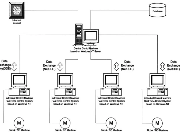
Windows NT has a great capability on networking. This feature is very important in building a network-based factory automation system. As Windows NT was designed based on the server-client model, it is naturally easy to build a distributed control system with it.
The advantage of networking power becomes obvious when we think of the fact that data exchange functionality is essential in distributed control. On distributed system, the operation commands and data should be sent through network. The system monitoring also should be done through network. So it is better for the server to have an almost complete control over the client machines. Under Windows NT (or Windows 95), this kinds of works can be done pretty without any major difficulty.
One of the most important functions that should be implemented on network for distributed control system for robotics or NC machines is trajectory update. The individual controller follows the trajectory given by central main controller residing in server computer. The main server receives data from individual machines, analyzes them, and sends the commands or updated data to the individual machines again. Under Windows
NT, this kinds of operations can be done by using "NetDDE (Network Dynamic Data
Exchange)" function. Originally the concept of DDE was developed as a mean for communication between two processes on multitasking environment. At the time when networking was not so popular and most of the works were done in only one computer,
DDE was just a tool for breaking the barrier of the separate processes. But as the
networking became one of the main features of the computer systems, its function has been expanded so that data exchange can be done between the processes running on different machines. For out purpose, this function can be used for the communication between the central control software and individual control software. The individual machines will be more dedicated to traditional machine control works, and the central machine will be more oriented to adjusting and optimizing of the whole manufacturing network consisting of individual machines. This concept is shown onFigure 8.
Data
:hange ttDDE)
5. NC Machine control using Windows NT Real Time Operating System
5.1 Virtual Motion Control Card (VMC)
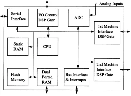
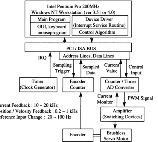
Based on the interrupt handling procedure described above, a software-oriented motion control system that runs on Windows NT is designed in this section. Figure 9 shows the schematic of a traditional motion control card with a dedicated co-processor and/or a DSP chip. Our objective is to replace this dedicated hardware board by software and simple, I/O interface boards, as shown in Figure 10. Although the basic technique of our software-only motion control applies to various actuators, the following description will be in the context of AC servo motors, the most prevailing drives for robots and machine tools.
CPU RAM
Flash
2nd Machine
Memory RAM & Interrupts
Dual
IInterace
Ported Bus Interface DSP Gate
SPorted
Figure 9. Traditional Motion Control Card
Most of the dedicated motion control cards perform a variety of real-time computations ranging from position and velocity feedback, feedforward compensation, and trajectory interpolation to high sampling-rate current feedback and parameter auto tuning. In addition, AC servo drives entail electronic commutation or software
I
commutation. Most electro-mechanical actuators are driven by PWM amplifiers which require the conversion of an analogue output to pulse width modulated signals that drive switching power transistors. Our objective is to perform all these tasks by software. Requirements for these computations differ in sampling rate and allowable time delay. According to the interrupt handling procedure in the previous section, all time-critical computations must be performed in Interrupt Service Routine (ISR), while non-time critical computations must be shifted to the Deferred Procedure Calls (DPC), as well as to user mode application programs. Also, high sampling-rate computations must have a higher priority level than that of low sampling-rate computations. The interrupt handling mode and priority level assigned to each computation task are as follows.
Current Fee' Position / V Reference 1i
Figure 10. Basic Structure of Windows NT based Real Time Control System
5.1.1
Current Feedback and PWM Computation (Interrupt Service Routines
with Priority Level 3)
is required. Both current feedback and PWM computation are governed by the electric characteristics of the drive system, which is much faster than mechanical motion. The majority of PWM power amplifiers use MOS-FET switching power transistors whose switching frequency is around 20 kHz. Therefore, the sampling rate of the current feedback loop, is bounded by the switching speed of the power transistors. The current standard in industry is a sampling interval of 50 gs to 100 jis (In our system, Tsc on Figure 11). This current feedback and the associated PWM computation are most time-critical and the shortest in sampling interval. Therefore, these are processed in the ISR with the highest priority level available for users' devices.
5.1.2 position and Velocity Feedback
Feedforward
Compensation,
Trajectory Interpolation, and Commutation
: (Interrupt
Service Routine with
Priority Level 4 (or 5))
The sampling rate required for mechanical motion control, i.e. position and velocity feedback, feedforward, and trajectory interpolation, is an order-of-magnitude slower than that of current feedback. The industrial standard is 0.5 ms to 5 ms (Tsp on Figure 11) in the sampling interval. Time delay longer than this sampling interval is not allowed for these computations, but this level of computation can be interrupted by the current feedback computation. As long as the computation is completed within the 0.5 ms to 5 ms sampling interval, the computation delay may not deteriorate the system control performance. Therefore, these computations are performed in ISR with a lower priority than that of the current feedback. This level of operations typically include data input from encoder counters, numerical differentiation of the encoder readings, digital filtering and observer computations, the read out of trajectory coordinates, and trajectory interpolation as well as the computation of feedback and feedforward control laws. For synchronous AC servo motors, three-phase currents flowing into the winding must be commuted by computing trigonometric functions. This commutation must be performed at the sampling rate comparable to that of position and velocity feedback, since it is associated with mechanical motion rather than electric.
5.1.3 Parameter Tuning,
Adaptive and Learning Control (Deferred
Procedure Calls and User Mode Application Program Level)
Today's advanced servo drive systems are capable of estimating load characteristics and adapting themselves to the unknown load. Automatic tuning of control parameters as well as adaptive and learning controls have been used in high performance drive systems. Computations for parameter tuning and adaptive and learning controls are not as time-critical as that of feedback and feedforward. Although those computations must be completed in real-time during the tracking control process, the adaptation and learning processes are much slower. Therefore those computations should be performed at Deferred Procedure Calls, which accepts interrupts from other devices. If the computation algorithms are complex, they should be processed at user-mode application programs rather than at the device driver.
5.1.4 Trajectory Data Update (User Mode Application Program Level)
The trajectory data should be updated periodically. Typical NC machines store trajectory data in the form of two kinds of information. One of them is the distance to move, and the other is the velocity. For the machine to trace the desired trajectory without stopping, the next trajectory data should be loaded in the memory before it reaches the current target point. Basically this job is not as time critical as that of position or velocity feedback, as long as the speed of data flow catches up the mechanical movement of machine. Sometimes the trajectory data are stored in hard disk, but sometimes they should be loaded from network in the case of distributed systems. Thus, it is better to design the system to carry out the trajectory data update at the application program level, rather than device driver level. The application program continuously monitors current position of machine, and sends out the next trajectory data to the device driver before the machine reaches the target point of trajectory data at the point in the device driver, so that the motion goes smoothly without fail.
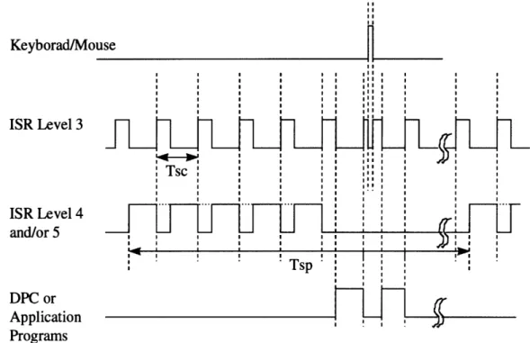
Figure 11 shows a conceptual timing chart illustrating the three levels of real-time control procedures described above. The current feedback and PWM computation to be performed in ISR Level 3 may be interrupted by keyboard and mouse alone : all the other
devices have lower priorities than this level. The current feedback operation will be delayed for a short time due to the interruption from a mouse or a keyboard, but its effect is totally negligible. The interrupt frequency of mouse and keyboard is more than 1000 times lower than the current loop sampling rate, and the current feedback computation is completed within its sampling interval, Tsc on Figure 11. Therefore, the current feedback operation would never be skipped. The position and velocity feedbacks to be performed in ISR Level 4 and/or 5 along with other computations including feedforward and trajectory interpolation may be interrupted by current feedback computation, as shown in the Figure 11. Since the position and velocity feedback have and order-of-magnitude slower sampling rate, the frequent interrupts may be no adverse effects on the control performance, as long as the CPU has an enough computing power and an appropriate I/O interface devices are used. To guarantee the performance we must investigate the time budget of the whole system. The time budget and requirements for I/O interface boards will be discussed in the later sections of this thesis.
Keyborad/Mo ISR Level 3 ISR Level 4 and/or 5 DPC or Application Programs I use ! ! II I I I I I I Il I I II I I 1 1 II !I I I I I I SI I I I ! I I I I I I SI I Il I I I I lI I Tsc . .... 1 1I SI I 1II I SI I 11 II 1 I SI I 11 II 1 I SI I I
5.2 Concept of Digital AC Servo
5.2.1 Traditional Method - Structure of AC Servo Control by Hardware
In order to control a brushless servo motor, the control device has to generate the magnetic flux perpendicular to the current. This should be done by electronic circuit in addition to the task of basic feedbacks for velocity and position. To control the current that flows into the motor, the method of PWM (Pulse Width Modulation) is generally used. Naturally there should be a circuit for generating PWM signal, and that for all three phases. To control the current more accurately, and to eventually enhance the performance of the motor, there also should be the circuit for current feedback. The overall block diagram of the control system for brushless servomotor is shown on Figure 12. The velocity control signal goes into DC-SIN conversion circuit. This circuit generates three-phase sine waves for commutation of the brushless servomotor. These three sine wave signals have phase difference of 120 degrees to each other. These analog signals go into PWM generation circuit and converted into corresponding digital signals, which are pulse width modulated. These TTL signals turns on and off the switching devices and the power inputs to motor are also turned on and off concurrently. The functions of these circuits are explained in detail in the following sections.
5.2.1.1 Sine wave generation circuit
This circuit is for generating sine waves with the rotor position serving as their phase. It is basically composed of ROM with sine value data in it. When the position information comes into the ROM as a form of address, the ROM gives out the corresponding sine value according to the position of the rotor. As the brushless servomotor is a three-phase motor, there should be three sine waves with phase difference of 120 degree. In practice phase V can be estimated by a simple analog operation through the equation V = - (U + W). Therefore, only phases U and W have to be generated by ROM [10].
Figure 12. Block Diagram of Brushless Servomotor Control System
5.2.1.2 DC-SIN conversion circuit
By means of the sine wave generation circuit, two-phase wine waves synchronized with rotor position are made. These values are multiplied by the reference input to increase or decrease the amplitude. In this way, the torque of the motor is controlled.
5.2.1.3 PWM Generation Circuit
The sine wave current should flow into the motor. To accomplish this, we can directly give the continuously-varying current using the analog feature of the switching devices. But this will cause enormous power loss and eventually result in motor failure due to the high temperature. So we have to make the current flow by on-off basis to reduce the power loss. This method is called PWM (Pulse Width Modulation).
In PWM method, the generated sine wave is compared with triangular wave with a fixed frequency. (The frequency of triangular wave is around 10 - 20 kHz when FETs are used as switching devices.) During the time when triangular wave has higher value than the sine-shaped current signal value (denoted TL on Figure 13), the switching device is turned off. On the contrary, during the duration that the current signal value is larger than triangular wave (denoted TH On Figure 13), the switching device is turned on, so that the
current flows into the motor. By changing the duty ratio, the overall current that flows into the motor can be controlled.
Triangular wave Generation Circuit Output Current Amplifier Output PWM Signal -A\ A
I\An
THI
/ TL /\ /I^
AlA
NrV
/,, \Figure 13. Pulse Width Modulation
5.2.2 New Method - PWM Generation by Software
The traditional method uses electrical circuit including comparator to generate the PWM signal. As analog signal is needed as the input to comparator, the circuit before the comparator on Figure 12 is composed of all analog components. Supposing that we use digital computer as a controller, this means we have to carry out DA conversion when we send out the reference value to the motor driving circuit. After this, analog signal goes through PWM circuit, and converted into PWM signal which is digital. (Actually this process can be seen as a kind of AD conversion.) As the result, the signal which was originally digital is converted to analog signal first, and converted to digital signal again to make the PWM generation circuit work. It is a kind of "loss" from the standpoint of efficiency.
The whole reason that we have to go through this tedious process is the comparator used for PWM signal generation. If we can generate PWM signal directly from original control reference input from computer (which is digital) without using the dedicated hardware such as comparator, it would be much better in terms of efficiency.
A 9
1
| I •