HAL Id: hal-02472712
https://hal.archives-ouvertes.fr/hal-02472712
Submitted on 10 Feb 2020
HAL is a multi-disciplinary open access
archive for the deposit and dissemination of
sci-entific research documents, whether they are
pub-lished or not. The documents may come from
teaching and research institutions in France or
abroad, or from public or private research centers.
L’archive ouverte pluridisciplinaire HAL, est
destinée au dépôt et à la diffusion de documents
scientifiques de niveau recherche, publiés ou non,
émanant des établissements d’enseignement et de
recherche français ou étrangers, des laboratoires
publics ou privés.
Local Oscillators and Digital Electronics for Compact
Atomic Clocks
Claudio Calosso, Bruno Francois, Rodolphe Boudot, Peter Yun, M Gozzelino,
E Bertacco, Salvatore Micalizio
To cite this version:
Claudio Calosso, Bruno Francois, Rodolphe Boudot, Peter Yun, M Gozzelino, et al.. Local Oscillators
and Digital Electronics for Compact Atomic Clocks. Microwave Technology and Technique Workshop,
Apr 2017, Noordwijk, Netherlands. �hal-02472712�
Local Oscillators and Digital Electronics for Compact Atomic Clocks
Claudio E. Calosso(1), Bruno François(1) (2), Rodolphe Boudot(2),
Peter Yun(3), Michele Gozzelino(1), Elio Bertacco(1), Salvatore Micalizio(1)
(1)INRIM, Division of Physics Metrology
Strada delle Cacce, 91 – Torino (Italy) [email protected]
(2)FEMTO-ST, CNRS, UBFC
26 rue de l’épitaphe 25030 Besançon (France)
(3)SYRTE, Observatoire de Paris, UPMC, PSL
77 avenue Denfert Rochereau 75014 Paris (France)
INTRODUCTION
Recently, the European Metrology Research Programme (EMRP) has funded the IND55 Mclocks joint research project [1] to develop compact and high-performing microwave clocks for industrial applications such as navigation, telecommunication, defence and precision instruments. This project aims at taking full advantage of better performing laser and microwave sources and innovative techniques to prepare and detect the atoms. In this regard, several European national metrological institutes (NMIs) or research institutes, devised new cell-based prototypes that exhibit unprecedented frequency stability performances, of the order of 10-13 at 1 s with a medium long-term in the range of
10-14 or better. Three typologies have been selected: vapour-cell clock based on pulsed optical pumping (POP) [2], on
cold atoms [3] and coherent population trapping (CPT) [4, 5, 6]. They are very different and allow matching many industrial applications having different levels of accuracy, stability, compactness, power consumption.
Despite their diversity, we decided to develop a generalized electronics able to run all of them with minimal modifications. This demanding task has been achieved by sharing the competences of the main NMIs involved in the project with the goal of obtaining a high-performing, flexible and simple platform. Particular attention has been devoted to generate a low phase noise and agile microwave [7], in order to interrogate the atoms with minimal Dick and intermodulation effect. The core is a module [8] that integrates an ultra-low noise 100 MHz oven controlled crystal oscillator (OCXO) and the first ×16 direct frequency multiplier stage. From its output at 1.6 GHz, three frequencies are generated by direct multiplication (1), programmable division (2) and Direct Digital Synthesis (DDS) (3) and then mixed together. By changing the multiplier device (×3, ×4, ×6), the division factor and the numerical frequency of the DDS, we can obtain 4.596, 6.834 and 9.192 GHz as required by rubidium and caesium atoms. The DDS also provides simultaneous and fast phase, amplitude and frequency modulations and allows implementing the patterns required by these clocks typologies. During the development of this scheme, we faced with new criticalities: AM to PM cross-correlation collapse in the measurement of ultra-low noise sources; DDS spurs and residual phase noise; very-low noise voltage required by the OCXO tuning. In order to provide compactness and flexibility, we integrated into a single board the low-frequency part of the scheme (two of the three arms) together with the electronics in charge of atomic signal detection and of frequency stabilization of the OCXO. This board is composed of DDSs, Analog to Digital Converters (ADC) and Digital to Analog Converters (DAC) driven by a Field Programmable Gate Array (FPGA) that provides synchronous operation at the level of 100 ns. The operational parameters are stored into the local memory and are used by a pattern generator to drive the DDSs (microwave and laser modulations) as well as several generalized loop controllers that process the atomic signals to extract the required information.
This platform has been tested with the Pulsed Optically Pumped (POP) clock at INRIM (Torino, Italy) and with the Double Modulation Coherent Population Trapping (DM-CPT) clock at SYRTE (Paris, France). For these clocks, the noise contribution to the short-term stability of each part has been evaluated. The total contribution is in the low 10-14 at
1 s, very close to the expected shot-noise level. In this regard, it was important to reduce the Dick effect down to 2×10 -14.
Besides clocks’ characterization, the electronics, thanks to its flexibility, allowed the implementation of new schemes, like the laser frequency lock to the internal cell. In this regard, it’s interesting to note the case of the POP clock, where, by simply processing the atomic signal from the internal cell, and without any additional hardware, we demonstrated the possibility to retrieve the frequency error and power level both of the microwave and of the laser. This information can
be used to stabilize all these quantities at the same time. The result is a significant reduction of the clock setup, very important, for example, in the frame of compact atomic clocks.
GENERALIZED ELECTRONICS
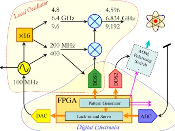
In this section we present the scheme (Fig. 1) of the generalized electronics, able to work with the clocks of interest for the Mclocks project. The main two parts are the local oscillator and the digital electronics. The main objectives of this scheme can be synthesized by three words: performance, simplicity and flexibility. For generalized electronics we mean a setup able to work with many types of clocks, in particular with the DMCPT clock [4], as well as with the POP clock [2]. These clocks are very different, but for both of them, the electronics has to generate a microwave to interrogate the atoms, to detect a power from them and to run other subsystems [acousto-optic modulator (AOM), polarizing switch…].
We point out that the electronics we implemented can be used also for a compact cold-atom clock like Rubiclock. In this case, the operation sequence is longer, because cold atoms are used and the Ramsey time can be as long as 30 ms with a repetition rate of tens of hertz. The scheme we implemented remains valid, with the only exception of the local oscillator that should be replaced by another one optimized at lower Fourier frequency.
Local Oscillator
We investigated the phase noise of several commercial oscillators both at 10 and at 100 MHz in order to find the one with minimal contribution to the clock stability. All the clocks interested by this EMRP project (except Rubiclock) have a repetition rate of the order of 10 ms and are sensitive to the phase noise in the range of hundreds of hertz. This range of frequency is high enough to make 100-MHz oscillators competitive with respect to 5-10 MHz ones, that, in turn, due to their superior performance at lower Fourier frequency, are the preferred choice for frequency standards based on cold atoms (atomic fountains, Horace, Rubiclock…). We chose a commercial module that integrates a 100-MHz OCXO with a ×16 frequency multiplier [8]. This module greatly simplifies the architecture. In this manner, frequency multipliers at tens of megahertz are avoided and, considering they are the most critical part of the synthesis chain, we obtain a significant improvement for what concerns both the additive noise and the sensitivity to temperature and other environmental parameters. In our case, the frequency multiplication starts at 100 MHz and the multiplier is tightly coupled with the OCXO. This solution reduces temperature sensitivity, taking advantage of the temperature stabilization of the quartz oscillator. The output at 100 MHz can be directly used by recent time-and-frequency devices or converted to 5/10 MHz by means of frequency dividers. We point out that in this case frequency division is less critical than frequency multiplication, because the divider is outside the multiplication chain and its residual noise does not contribute to the Dick/intermodulation effect.
The synthesizer is implemented as in [9], where a DDS signal is up-converted twice, to reach the hyperfine atomic frequency. This scheme has the agility of the DDS and the noise performance of a fixed frequency synthesis. The use of two steps allows reducing the requirements of filters and provides additional degrees of freedom to match both the Rb and Cs frequencies. In this sense, convenient numbers for the high frequency (HF) branch are 4.8, 6.4 and 9.6 GHz, that are 1.6 GHz multiplied by 3, 4 and 6 respectively. In addition, 1.6 GHz = 16 × 100 MHz is a convenient frequency, because a factor 16 is suitable both for frequency multiplication and division (i. e. a sequence of dividers by two). There is the same possibility also for the intermediate frequency (IF), that can be obtained by direct multiplication from the 100 MHz or by division from 1.6 GHz. By changing the multiplier device (×3, ×4, ×6), the division factor and the numerical frequency of the DDS we can obtain 4.596, 6.834 and 9.192 GHz as required by rubidium and caesium atoms (Fig. 1.a).
The scheme we adopted is very flexible in term of technology, because it is open to frequency division and multiplication. We decided to use direct multiplication for the high frequency (HF) branch, because we found it has superior performance, and to obtain the intermediate frequency (IF) by division, because it is more simple and more
FPGA D D S 2 D D S 1
DAC Lock-in and Servo
4.8 6.4 GHz 9.6 200 MHz 400 ×16 100 MHz 4.596 6.834 GHz 9.192 ADC Pattern Generator Digital Electronics
Fig. 1. Block diagram of the generalized electronics. It can subdivided into local oscillator and digital electronics.
a)
b)
(e) DM CPT old synthesis chain
166 Hz to 15 kHz
230 Hz to 1250 Hz
c)
d)
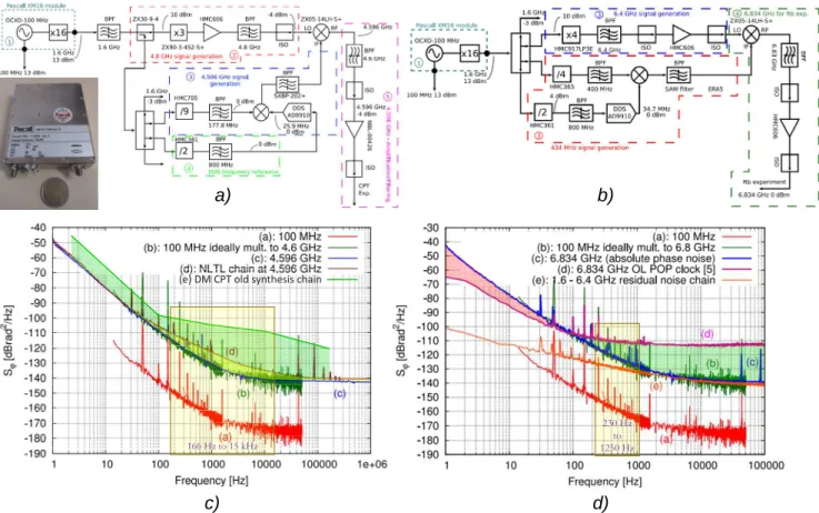
Fig. 2. Local Oscillator block diagram for CPT (a) and for POP (b) and their phase noise: (c) and (d) respectively. The absolute phase noises of the synthesized signals are compared with the contribution of the OCXO and of the synthesis
chain. The improvements with respect to previous solutions are highlighted.
flexible. In this regard, we used programmable frequency dividers such as HMC705 from Analog Devices, formerly Hittite, that allows to switch from Rubidium to Cesium configuraton by just changing jumpers settings.
Having in mind this approach, it is possible to read Fig. 2. It reports the detailed diagrams of the Double Modulation CPT (a) and POP (b) local oscillators. (a) generates 4.596 GHz required by the DM CPT scheme (Cs). The HF is 1.6 GHz × 3 = 4.8 GHz, the IF is 1.6 GHz / 9 = 177.8 MHz and the LF is 25.9 MHz from the DDS, clocked at 1600 MHz / 2 = 800 MHz. The output is HF – (IF + LF) with a power up to 27 dBm, as required by the Electro-Optic Modulator.
The synthesis chain of the POP feeds directly the Rb atoms at 6.834 GHz by means of a microwave cavity. The required power is much lower, less than one milliwatt, depending on the cavity quality factor. Here, the HF is 1.6 GHz × 4 = 6.4 GHz, the IF is 1.6 GHz / 4 = 400 MHz and the LF is 37.4 MHz from the DDS. The output frequency is HF + IF + LF.
In both synthesizers, after each frequency conversion there is a low/band-pass filter that selects the frequency of interest and, if necessary, there are amplifiers and isolators. We grouped the intermediate and low frequency part of the synthesis chain in a single board, together with the rest of the digital electronics. In this manner, the coaxial part is limited to the HF part, with beneficial effects on size, weight and cost.
Fig. 2.c and 2.d show the final performance of the new local oscillator in the DM CPT (c) and POP (d) configurations. In yellow, it is reported the region where the noise contributes to the clock stability, while in green (red) is reported the improvement (worsening) with respect to previous synthesis chains.
Fig. 2.c shows the LO absolute phase noise (c) at the 4.956 GHz, compared with the previous ones (d, e). (d) is a recent design based on NLTL [10] used for the Push-Pull CPT [5]. In the range of interest, from 100 to 10 kHz, the new LO improves the phase noise by about 6 dB. (e) is the previous LO used for the DMCPT clock. Here the improvement is more than 20 dB. Fig. 2.d compares the phase noise of the new LO at 6.8347 GHz (c) with the one (d) used previously for the POP clock [2]. There is a break-even-point at about 100 Hz. At higher frequency, that is the region interested by Dick effect, it is evident the advantage in using a 100 MHz OCXO (c) with respect to a 10 MHz one (d), especially for
what concern the noise floor. On the opposite, at lower frequency, the new LO is less stable and it requires a tighter
frequency lock of the OCXO. We point out, that, in case of Rubiclock, (d) should lead to better results than (c), because cold-atom clocks have longer clock cycle.
We estimated the Dick effect contribution [7] at the level 3.1×10⁻¹⁴ and 2.0×10⁻¹⁴ for the pulsed CPT and for the POP
clocks respectively. The improvement, a factor two and three respectively, leads the Dick effect contribution in the low 10-14, very close to the shot noise limit of the clocks.
During the development of this new architecture we had to face new issues, like (1) AM-PM cross-correlation collapse [11] for what concerns the evaluation of the OCXO, (2) the noise and the spurs of the DDS [13] and (3) the OCXO driving that now requires low noise voltage.
The first criticality is related to the fact that Dick/intermodulation effect is minimized by using ultra-low noise oscillators, that, in turn, are difficult to be measured. Fig. 3.a shows, as an example, the phase noise at 1.6 GHz of the same module measured with the same model of two different commercial instruments [12]: one at the manufacturer laboratory (magenta curve) and one at the laboratory in Femto-ST (green curve). In the region of interest, the discrepancy between the two measures is as high as 10 dB and this leads to an unacceptable error during the estimation of the Dick/intermodulation effect.
The second criticality is related to the DDS. The use of a 100 MHz OCXO reduces the noise floor of the microwave and tightens the specification of the DDS by at least 20 dB. In addition, the simple numbers of the synthesis chain for HF and IF branches have been possible thanks to higher frequencies in the DDS branch. Being the phase noise of a DDS, in general, proportional to its output frequency [13], it results in an additional requirement to it. In this regard, the best DDS commercially available is the AD9910 from Analog Devices, thanks to its low residual phase noise and to the 14-bit resolution of its DAC. We recall, that the spur power is inversely proportional the DDS lsb squared and to the clock frequency. 1 µV/√Hz 10 nV/√Hz a) Abs. PN of 6.834 GHz b) « « of 4.596 GHz c) AD9910 PN @ 37 MHz d) « « « 28 MHz b) c) Region of interest a)
Fig. 3. New criticalities in the new local oscillators: AM-PM cross-correlation collapse (a), noise and spurs of DDS (b) and voltage driving of the OCXO (c).
Fig. 3.c is related to the third criticality. It shows the degradation of the OCXO phase noise induced by a 1µV/√Hz control voltage (carrier 100 MHz). It was necessary to reduce it by 40 dB, at the level of 10 nV/√Hz, to make negligible its contribution. This criticality arises from the high sensitivity to the control voltage combined with the low phase noise of the OCXO.
Digital Electronics
The natural way to implement a highly reconfigurable electronics that runs several types of clock is the digital approach. For this reason, as reported in Fig. 1.b, we grouped into a single board all the circuits that are interested by the clock operation: the DDS for the synthesis chain, the DDS for the AOM to modulate the laser, the ADC that acquires the atomic signal and the DAC that drives the OCXO are the most important. This board is based on an FPGA that acts as a bridge among them, providing great flexibility. The FPGA has many functions: 1) it hosts the pattern generator that drives each block according to the sequence of steps typical of the particular clock; 2) it implements the frequency loop function; 3) it interfaces a computer for setting the working parameters and for monitoring the internal data flow. Each functionality is independent from each other.
This architecture is suitable to run many types of clocks, since the operation of each clock can be decomposed as a sequence of elementary steps, where the basic clock blocks change their status. By example, the two microwave pulses of the Ramsey interrogation are obtained from changing the numerical amplitude of the DDS; the pumping pulse by changing the numerical amplitude to the DDS that drives the AOM; the detection window by enabling a numerical accumulator…
All this information is stored in a local memory. The pattern generator read this data and drives the sub-systems accordingly. By changing this information, we can change the operating condition of the clock or, even, the type of clock: POP, Pulsed Push-Pull CPT, DM CPT…
Noise Budget
We evaluated the contribution of the electronics we developed for the DM CPT and POP clocks (Tab. 1). For both clocks, the main contribution is the intermodulation/Dick effect ( 2×10-14 at 1 s). Then there is the contribution of the
OCXO frequency stability that is reduced by the frequency lock loop from 2×10-12 to 7×10-15 (τ = 1 s). At the same level
we found the contribution of the ADC noise. The electronics we developed has a total contribution to the short-term stability of the clock at the level of 2.3×10⁻¹⁴ (1 s), comparable with the shot noise limit of the two clock. The total
contribution to the short-term stability of the clocks is very close to the shot-noise limit.
CLOCK CHARACTERIZATION AND TUNING
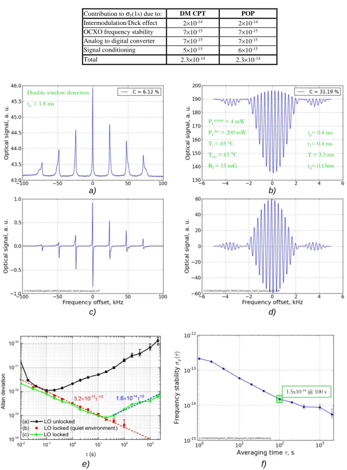
We tested the local oscillator and the digital electronics and we report in Fig. 3 some of the results for the DM CPT (a, c, e) and for the POP (b, d, f) clocks. (a) and (b) are the atomic signal as a function of the microwave frequency. (a) is typical of a clock with continuous operation, while (b) have an oscillating behaviour, typical of the Ramsey interrogation. (c) and (d) are the dispersive signals obtained by running a pattern that differentiates the atomic response with respect to the microwave frequency. For both clocks we obtained a frequency stability in the low 10-13 for
averaging time of 1 s as shown by (e) and (f). According to Tab. 1, this stability is not limited by the electronics we developed, whose contribution is about one order of magnitude lower.
ADVANCED TECHNIQUES
The FPGA allows storing more than one hundred elementary steps. In this manner, it is possible to implement very complex schemes. We used this facility to investigate in depth the critical aspects of these clocks (i. e. FM-AM and AM-AM from laser) and to demonstrate new schemes.
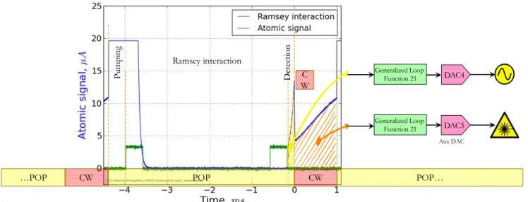
To demonstrate the powerfulness of this scheme, as an example, we report the frequency lock of the laser to the internal cell, by using the light shift induced to the atoms by a laser and microwave fields applied at the same time.
As reported in Fig. 4, we decided to run together both the POP clock and CW clock, just because the POP clock is very insensitive to the laser frequency while the CW clock is very sensitive to it. The information retrieved during the POP operation is used to frequency lock the OCXO, being, at the first order, insensitive to the laser frequency. At this point, the information detected during the CW phase, is representative of the laser frequency and can be used to frequency lock the laser to the internal cell, avoiding the use of the external cell. The preliminary results are encouraging. They exhibits a frequency stability of 5x10-13 and 1.5×10⁻¹⁴ at 1 s and 10000 s respectively, with a drift of the order of 10-14
CONCLUSIONS
Table 1. Noise budget for the DM CPT and POP clocks
Contribution to σy(1s) due to: DM CPT POP
Intermodulation/Dick effect 2×10-14 2×10-14
OCXO frequency stability 7×10-15 7×10-15
Analog to digital converter 7×10-15 7×10-15
Signal conditioning 5×10-15 6×10-15 Total 2.3×10⁻¹⁴ 2.3×10⁻¹⁴ tp= 0.4 ms t1= 0.4 ms T = 3.3 ms td= 0.15ms PLpump= 4 mW PLdet= 200 mW Ti= 65 °C Text= 63 °C B0 = 15 mG
Double window detection tw= 1.8 ms
a)
b)
d)
c)
1.5x10⁻¹⁴@ 100 se)
f)
Fig. 3. Results obtained by using the digital electronics with the DMCPT (a, c, e) and the POP (b, d, f): spectroscopy signals (a, b), dispersive signal (c, d) and final frequency stability (e, f).
CONCLUSIONS
We presented the electronics we developed for the clocks involved in the IND55 EMRP project. This electronics has been designed to be general, in order to be used with different clocks with minimal modifications. Here we presented the results obtained with the DM CPT and POP clocks, that are very different. We demonstrated its capability to support all the development phases: form the physical investigations to the clock optimization. We calculated the contribution to the short term stability of these two clock and we found it is in the low 10-14, very close to the shot-noise limit. In this
regard, an important role is represented by the local oscillator phase noise reduction. In addition to low noise performance, the new architecture can be adapted to generate the Rb and Cs hyperfine frequencies. The digital implementation guarantees an high degree of flexibility that allows to run very different clock typologies and to implement innovative schemes such as the frequency lock of the laser to the internal cell.
References
[1] www.inrim.it/Mclocks
[2] Micalizio S, Calosso CE, Godone A, Levi F. “Metrological characterization of the pulsed Rb clock with optical detection” Metrologia, vol. 49, p. 425-436, 2012, ISSN: 0026-1394, doi: 10.1088/0026-1394/49/4/425..
[3] De Sarlo, L and Langlois, M and Holleville, D and Lours, M and Dimarcq, N and Schaff, J-F and Bernon, S and Desruelle, B. “Preliminary Test of a Cold-Atom Based Clock Prototype on a Microgravity Platform”. Proceedings of the 24th European Frequency and Time Forum
[4] P. Yun, F. Tricot, C. E. Calosso, S. Micalizio, B. François, R. Boudot, S. Guérandel, and E. de Clercq. “High-Performance Coherent Population Trapping Clock with Polarization Modulation”. Phys. Rev. Applied, vol. 7, issue 1, 2017, doi: 10.1103/PhysRevApplied.7.014018
[5] M. Abdel Hafiz, R. Boudot. A coherent population trapping Cs vapour cell atomic clock based on push-pull optical pumping, Journal of Applied Physics, 118, 124903 (2015).
[6] J. M. Danet, M. Lours, S. Guérandel, E. De Clercq, Dick effect in a pulsed atomic clock using coherent population trapping, IEEE Trans. On UFFC 61, 4 (2014).
[7] Francois B, Calosso CE, Hafiz MA, Micalizio S, Boudot R. “Simple-design ultra-low phase noise microwave frequency synthesizers for high-performing Cs and Rb vapor-cell atomic clocks” Review of Scientific Instruments, vol. 86, issue 9, Sep-2015, DOI: 10.1063/1.4929384 .
[8] www.pascall.co.uk
[9] Calosso CE, Micalizio S, Godone A, Bertacco EK, Levi F. “Electronics for the pulsed rubidium clock: Design and characterization”. IEEE Transactions on Ultrasonics Ferroelectrics and Frequency Control, vol. 54, p. 1731-1740, 2007, ISSN: 0885-3010, doi: 10.1109/TUFFC.2007.458.
Ramsey interaction POP CW CW …POP P u m p in g D et ec ti o n C W Generalized Loop Function 21 DAC4 DAC5 Generalized Loop Function 21 Aux DAC POP…
Fig. 4. Principle of operation for frequency lock the laser to the internal cell. Two pattern are alternated with low (POP) and high (CW) FM to FM sensitivity. The information retrieved from the POP (CW) is used to frequency lock the OCXO
[10] Francois B, Calosso CE, Hafiz MA, Micalizio S, Boudot R (2016). “Simple-design ultra-low phase noise microwave frequency synthesizers for high-performing Cs and Rb vapor-cell atomic clocks”. Review of Scientific Instruments, vol. 86, issue 9, Sep-2015, DOI: 10.1063/1.4929384 .
[11] C. W. Nelson, A. Hati, and D. A. Howe. “A collapse of the cross-spectral function in phase noise metrology”. Review of Scientific Instruments, vol. 85, 024705 (2014); doi: http://dx.doi.org/10.1063/1.4865715
[12] www.keysight.com/en/pd-1081579-pn-E5052B
[13] Calosso CE, Gruson Y, Rubiola E (2012). “Phase noise in DDS”. Proc. International Frequency Control Symposium (IFCS) p.777-782, Baltimore, MD, USA, 21-25 May 2012.