Advanced Propulsion for Microsatellites
by
Vadim Khayms
B.S., Aeronautics & Astronautics, MIT (1995)
B.S., Physics, MIT (1995)
S.M., Aeronautics & Astronautics, MIT (1997)
Submitted to the Department of Aeronautics & Astronautics
in partial fulfillment of the requirements for the degree of
Doctor of Philosophy in Aeronautics & Astronautics
at the
MASSACHUSETTS INSTITUTE OF TECHNOLOGY
September 2000
©
Massachusetts Institute of Technology 2000. All right TCHTSINSTITUTEOF TECHNOLOGY
-NOV 17 2000
Author ...
... ..
RARIES
Department of Aeronautics & Astronautics
RO
June 23, 2000 Certified by ... Manuel Martinez-Sanchez Professor Thesis Supervisor R ead by ... ... Jack L. Kerrebrock Professor Thesis Reader R ead by ... ... Akintunde I. Akinwande Professor Thesis Reader Read by ... ... George R. Ricker Jr Seqior Research Scientist Thesis Reader Accepted by ... e WCaesbi ttm W. HCmtag oGoa d
Advanced Propulsion for Microsatellites
by
Vadim Khayms
Submitted to the Department of Aeronautics & Astronautics
on June 23, 2000, in partial fulfillment of the requirements for the degree of
Doctor of Philosophy in Aeronautics & Astronautics
Abstract
Microsatellites have become increasingly popular in recent years as they offer sig-nificant cost savings, higher reliability, and are generally more affordable for a large variety of commercial applications. Since many microsatellite missions require consid-erable propulsion capabilities, miniaturization of the propulsion subsystem is critical in the design of most miniature spacecraft. A broad range of existing propulsion technologies have been considered for the purpose of identifying those devices which maintain high performance at small scale. Scaling laws were developed for each of the selected devices so as to preserve, whenever possible, the basic non-dimensional quantities which ultimately determine the performance of the individual thrusters at small scale. Hall thrusters were initially identified as most promising. In an effort to miniaturize the Hall thruster, a number of complications have been encountered. Some of the most troublesome were higher magnetic field requirements, larger internal heat fluxes and temperatures, and difficulties associated with the manufacturing of the various miniaturized components. In order to validate the proposed scaling laws, a 50 Watt Hall thruster has been designed, manufactured, and tested in a vacuum tank. Results of the experimental testing indicate that, although the maximum thrust levels obtained were on the order of 1.8 mN, about two thirds of the nominal design value, the propellant utilization efficiencies were unexpectedly low at approximately 40%. Close examination of the magnetic assembly has shown that the tip of the iron center pole was overheating during operation due to the insufficient heat conduction. The tip temperatures were estimated to reach 900'C, exceeding the Curie point of iron. As a consequence of the change in the magnetic field profile and the resultant leakage of electrons, the observed ionization fraction and, therefore, the utilization efficiency were lower than expected. Despite the low efficiencies, which were most likely caused by the design imperfections rather than physical limitations, the effort to miniaturize a Hall thruster has provided a number of useful insights for any such attempts in the future. Most importantly, this work has highlighted the generic dif-ficulty, common to all plasma thrusters, associated with the increase of the plasma density as the scale of the device is reduced. The consequences of strict scaling, most notably the higher particle fluxes which cause an increase in the erosion rates and
significant loss of operating life at small scale, created a strong incentive to search for
propulsion schemes which avoid ionization by electron bombardment.
In the quest for a more durable device that could operate at low power, yet provide sufficient operating life to be of practical interest, colloidal thrusters were considered for miniaturization. These are representatives of a technology of electrostatic acceler-ators which does not rely on ionization in the gas phase and, hence, their operating life is not compromised at small scale. In addition to their intrinsically small dimensions and extremely low operating power levels, eliminating the need for further "miniatur-ization", colloidal thrusters possess a number of desirable characteristics which make them ideal for many microsatellite missions. Although the physics of electrospray emitters has been studied for decades, many of the mechanisms responsible for the formation of charged jets are still poorly understood. In order to gain further insight,
a semi-analytical fluid model was developed to predict the effects of fluid's viscosity
on the flow pattern. Results of the analysis indicate that over a broad range of oper-ating conditions viscous shear flow is insignificant in the vicinity of the jet irrespective
of the fluid's viscosity. In an attempt to further understand the physics of colloidal
thrusters, specifically the effects of internal pressure, electrode geometry, and the in-ternal electrostatic fields on the processes involved in the formation of charged jets, a detailed electrohydrodynamic model was formulated. A numerical scheme was devel-oped to solve for the shape of the fluid meniscus given a prescribed set of operating conditions, fluid properties, and electrode configurations. Intermediate solutions for the conical region have already been obtained, however, convergence in the vicinity of the jet requires further studies. A fully developed model promises to provide valuable information and guidance in the design of colloidal thrusters.
Thesis Supervisor: Manuel Martinez-Sanchez Title: Professor
Acknowledgments
Successful completion of this work would not have been possible without the help, advice, and support of many individuals, some of whom I would like to thank here.
First and foremost, I would like to thank my advisor, Prof. M. Martinez-Sanchez for his patience, insight, and continuous support over the course of my graduate education. His immense knowledge of absolutely everything, his enthusiasm, and
willingness to share this knowledge have been most invaluable.
I would like to thank Prof. Edgar Choueiri, Bob Sorenson, and John Ziemer at the
Electric Propulsion and Plasma Dynamics Lab of Princeton University for allowing us
to use their vacuum facilities to test the miniature thruster, for their time, resources,
and support. I would also like to thank the personnel of the Busek company, Vlad Hruby and Jeff Monheiser, for loaning some of their equipment, without which many
of the experiments would not have been possible, and for letting us use their vacuum facilities to perform preliminary test runs. I am also in debt to the personnel at the
Electric Propulsion Lab at the Edwards Air Force Base, to Ron Spores and Greg
Spanjers, for supporting laboratory testing at their facilities, and to Mike Fife and Jaime Malak for devoting their time in the lab.
I am also grateful to the engineering staff of the Dexter Magnetic Materials
Divi-sion (Permag) for their support in the design and simulation of the magnetic circuitry and assembly of the microthruster components. Many thanks to the machine shop personnel of the Draper Laboratory, especially to Edward McCormack for his valu-able advice and help in manufacturing some of the low-tolerance components for the Hall thruster. His capabilities in performing seemingly impossible machining tasks
were quite impressive.
I would also like to thank Bohus Ondrusek for his help in the testing phase of
the miniature Hall thruster. Always eager to help, his experience with cathodes was extremely valuable in the initial attempts to operate the Hall thruster.
Many thanks to the staff members at the department of Aeronautics &
Donald Wiener. Thanks to Sharon Leah Brown and Peggy Edwards for all the cook-ies, candcook-ies, and last but not least, all the help during the past several years. Also, thanks to the undergraduate students who have helped with the assembly of the thrust balance, most notably Maria Ishutkina, Jeff Reichbach, and Marshall Brenizer.
I would also like to thank Bernard Asare, my former roommate and an officemate,
for all the coffee and all the stimulating discussions.
I am most grateful to my girlfriend, Sofya, for proof-reading half of my thesis, and
then insisting that I acknowledge her contribution to rocket science; and, of course, for all the moral support and help as this document was slowly coming into existence.
I am most indebted to my parents, Alik and Nelya, as well as to my brother Alex
for always believing in me and for constantly inspiring and encouraging me to do my best. My coming and successfully graduating from MIT (on multiple occasions) is credited exclusively to them.
Contents
1 Introduction
1.1 Advantages of Micro-satellites . . . .
1.2 Propulsion System Options . . . . 1.3 Goals & Objectives . . . . 2 Scaling of Existing Propulsion Technologies
2.1 Introduction . . . . 2.2 Hall Thrusters . . . . 2.2.1 Principles of operation . . . .
2.2.2 Ionization efficiency . . . .
2.2.3 Confinement of electrons . . .
2.2.4 Magnetic confinement schemes
2.2.5 Performance analysis...
2.3 Ion Engines . . . .
2.3.1 Principles of operation . . . . 2.3.2 Confinement of neutrals . . . 2.3.3 Confinement of electrons . . .
2.3.4 Scaling of the ion optics . . .
2.4 Pulsed Inductive Thrusters . . . .
2.4.1 Principles of operation . . . .
2.4.2 Loss mechanisms and scaling .
2.5 Contact Ionization Thrusters ...
2.5.1 Principles of operation 13 13 14 15 17 . . . . 1 7 . . . . 1 8 . . . . 1 8 . . . . 1 8 . . . . 2 0 . . . . 2 2 . . . . 2 3 . . . . 2 4 . . . . 2 4 . . . . 2 5 . . . . 2 7 . . . . 2 8 . . . . 3 0 . . . . 3 0 . . . . 3 0 . . . . 3 3 . . . . 33
2.5.2 Scaling of contact ionization thrusters .3
2.6 Colloidal Thrusters . . . . 37
2.6.1 Principles of operation . . . . 38
2.6.2 Applicability to micro-propulsion . . . . 39
2.7 Field-Effect Electrostatic Propulsion (FEEPs) . . . . 41
2.7.1 Principles of operation . . . . 41
2.7.2 Applicability to micro-propulsion . . . . 42
2.8 Summary . . . . 43
2.8.1 Hall thrusters . . . . 43
2.8.2 Ion engines . . . . 44
2.8.3 Pulsed inductive thrusters . . . . 44
2.8.4 Contact ionization thrusters . . . . 45
2.8.5 Colloidal thrusters . . . . 45
2.8.6 Field-Effect Electrostatic Propulsion . . . . 46
2.8.7 Recommendations . . . . 46
3 Design of a 50W Hall Thruster 47 3.1 Introduction ... ... . . . .. . . . . .... ... 47
3.2 General Design Considerations . . . . 48
3.3 Magnetic Circuit Design . . . . 49
3.4 Thermal Design/Material Selection . . . . 53
3.5 Cathode Design . . . . 56
3.6 Final Design . . . . 56
4 Experimental Testing of a 50-Watt Hall Thruster 59 4.1 Preliminary testing attempts . . . . 59
4.2 Testing Facility . . . . 62
4.2.1 Vacuum Tank . . . . 62
4.2.2 Thrust Balance, Calibration, & Data Acquisition . . . . 63
4.2.3 Cathode . . . . 64
4.2.4 Flow system . . . . 65
4.3 4.4 4.5 4.6 Test results . . . . Analysis . . . . Alternative scaling scenarios . . . . Conclusions and recommendations . . . .
5 Physics of Colloidal Thrusters
5.1 Literature Review . . . . 5.1.1 Scientific work in the area of electro-spray physics
5.1.2 Developments in the field of colloidal propulsion .
5.2 Weaknesses of current models . . . .
5.3 Scaling and performance of colloidal thrusters . . . . 5.3.1 Electrostatics of cone-jet emitters . . . .
5.3.2 Formation of the jet . . . .
5.3.3 Production of droplets . . . .
5.3.4 Regimes of operation . . . .
5.4 Ion em ission . . . .
5.4.1 Mixed-regime operation . . . .
6 Creeping Flow Model for a Conical Meniscus
6.1 Introduction . . . .
6.2 Model Formulation . . . .
6.3 Numerical Procedure and Results . . . .
7 Electro-Hydrodynamic Model of a Cone-jet Emitter 7.1 Introduction and Literature Survey . . . .
7.2 Model description and assumptions . . . .
7.3 External electrostatics model . . . .
7.4 Electrohydrodynamics at the fluid interface . . . . 7.4.1 Surface electrostatics . . . . 7.4.2 Stress and momentum balance . . . .
7.5 Results of the numerical model . . . .
127 . . . . 127 . . . . 129 . . . . 131 . . . . 135 . . . . 135 . . . . 138 . . . . 140 65 67 70 76 80 80 80 82 84 87 87 93 97 100 106 110 115 115 117 123
7.5.1 Summary of the model . . . . 140
7.5.2 Preliminary numerical results . . . . 142
7.6 Conclusions . . . . 143
8 Conclusions and Recommendations for Future Work 145 8.1 Contributions to the scaling methodology . . . . 145
8.2 Recommendations pertinent to scaling of Hall thrusters . . . . 148
8.2.1 Theoretical work . . . . 148
8.2.2 Experimental work . . . . 149
8.3 Contributions to the modeling of colloidal thrusters . . . . 150
8.4 Recommendations pertinent to the modeling of colloidal thrusters . 151 A Additional Considerations in the Scaling of Hall Thrusters 153 B Additional Considerations in the Design of a 50 W Hall Thruster 158 B.0.1 Vacuum insulation . . . . 158
List of Figures
2-1 Hall thruster schem atic . . . . 2-2 Scaling of plasma density . . . .
2-3 Scaling of magnetic confinement schemes . . . .
2-4 Ion thruster schematic . . . .
2-5 PIT schem atic . . . . 2-6 Schematic of a contact ionization thruster . . . . 2-7 Current density vs. temperature for cesium-tungsten configuration 2-8 Colloidal thruster schematic .-. .. . - ---...
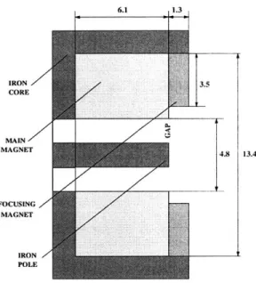
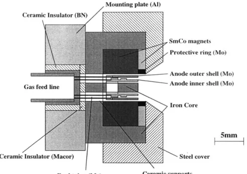
2-9 FEEP schematic . . . . 3-1 Magnetic circuit geometry (all dimensions in mm) . . 3-2 Magnetic flux profile (courtesy of Dexter Magnetics) . 3-3 Magnetic circuit assembly . . . .
3-4 Anode schematic [all dimensions in inches (mm)] . . .
3-5 A node . . . .. .. . . . . 3-6 Final design schematic . . . . 3-7 Anode assembly . . . . 3-8 Final assembly . . . . 4-1 4-2 4-3 4-4 4-5 Operational testing . . . . Vacuum facility schematic . . .
Cooling jacket . . . . 50W Hall thruster performance 50W Hall thruster performance
19 21 23 25 30 33 35 38 . . . . 42 . . . . 51 . . . . 51 . . . . 52 . . . . 55 . . . . 55 . . . . 57 . . . . 58 . . . . 58 . . . . 6 0 . . . . 6 3 . . . . 6 4 . . . . 6 6 . . . . 6 7
Test data ... ...
Dependence of the efficiency on the mean free path parameter
I.
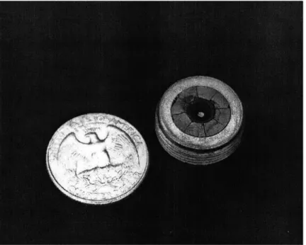
. General scaling strategies . . . . Scaling scenarios . . . . Erosion pattern at the center pole piece . . . . 5-1 Conical geom etry . . . . 5-2 Operating regimes: a) charge relaxation effect, b) dynamic pressureeffect . . . .... . . ... . . ... . . . .. . . . 5-3 Onset of the minimum flow rate (boundary indicates maximum allow-able current for a given flow rate) . . . . 5-4 Onset of ion emission (dashed line indicates the current obtained in
the absence of ion emission) . . . . 5-5 Mixed-regime scenario . . . .
6-1 Coordinate definitions . . . . 6-2 Streamline map (horizontal axis is the axis of symmetry, all dimensions
given in m eters) . . . .
7-1 Computational domain (assuming
7-2 Coordinate definition . . . .
7-3 Computational grid . . . . 7-4 Surface field configuration . . . . 7-5 Internal field configuration .
7-6 Force diagram . . . .
7-7 Sample solution . . . . B-1 Vacuum gap insulation . . . . B-2 1-D thermal model . . . . cylindrical symmetry) . . . . 4-6 4-7 4-8 4-9 4-10 138 143 . . . . 159 . . . . 160
B-3 (a) Anode temperature profile; (b) Radiative heat fluxes
68 73 74 75 79 91 101 103 111 114 118 124 131 132 133 135 137 161
List of Tables
Chapter 1
Introduction
1.1
Advantages of Micro-satellites
Ever since the very beginnings of man's ventures into space, costs of delivering and deploying complex multi-functional spacecraft and scientific instruments into orbit have played a major role in their design and implementation. Although launch vehicle capabilities have improved significantly over the past thirty years, allowing larger and more capable spacecraft to be launched, recent changes in government policies and defense spending as well as the resulting budget constraints have shifted the emphasis of most spacecraft manufacturers almost entirely to cost. Reduction of these costs is the main incentive for producing and flying small scale satellites [1].
Although the benefit of flying smaller and, therefore, lighter spacecraft from the overall launch cost perspective may be apparent, additional advantages make micro-spacecraft a viable alternative for a number of potential missions. For instance, func-tionality of a single spacecraft can be effectively distributed among several smaller vehicles, thus reducing the complexity of each individual spacecraft, reducing the de-sign and manufacturing costs per satellite, and improving the reliability of the overall system. The need for integrating a number of diverse and, at times, incompati-ble functions on a single spacecraft in the past has produced compromised solutions which often suffered from poor and inefficient designs. By redistributing functionality and focusing on the individual subsystems and components at a functional level,
sig-nificant improvements in the design efficiency could be achieved. Lastly, reduction of the complexity of individual spacecraft would facilitate rapid prototyping, lower the development life-cycle, and stimulate more efficient and economical production and manufacturing practices. Even if the functionality of a spacecraft were reduced in proportion, lower costs of the resulting less capable spacecraft may attract additional users thus broadening the spectrum of applications and opening up new avenues in space exploration [2].
The recent emphasis on cost reduction and down-sizing of spacecraft has forced a reevaluation of technologies which may have critical impact on spacecraft mass. For many commercial, scientific, and military missions on-board propulsion has been a dominant contributor to the overall mass of the spacecraft. As many of these mis-sions generally require a wide range of on-orbit functions, including orbit raising, drag makeup, station-keeping, and attitude control, the use of miniature high per-formance propulsion on board of these spacecraft would help reduce the subsystem weight and, therefore, aid in achieving the ultimate goal of deploying cost-effective and reliable spacecraft. Recent communications and remote sensing missions intro-duce additional requirements for constellation maintenance and mandatory end-of-life deorbit, both of which result in the increase of the overall propulsive requirements. New spacecraft architectures, costs of ground testing and handling of toxic or hyper-golic propellants all lead to the considerations of alternative propulsion technologies, once again demonstrating the urgent need for development of more capable miniature high-performance propulsion.
1.2
Propulsion System Options
The choice of an appropriate propulsion system for most spacecraft is primarily dic-tated by the specific mission objectives that nowadays demand increasingly better propulsion capabilities. A number of recent scientific missions, such as JPL's LISA mission (Laser Interferometer Space Antenna), require low thrust propulsion capable of delivering precise impulse bits at the thrust level of about 1-20 pN. Due to the
insignificant use of on-board propulsion and small overall velocity increments (AV) such missions can tolerate lower specific impulse and efficiencies. On the other hand, missions intended for long duration deep space exploration (such as New Millennium
DS-1), which require large velocity increments, usually optimize in the high specific
impulse (Ip) regime at 2, 000 sec and above. A large number of near-Earth missions such as constellation flights or missions requiring north-south station keeping, drag makeup, and other moderately intensive orbit maintenance maneuvers, all optimize in the intermediate I1, range between 1, 000 and 1, 600 sec. Electric thrusters capa-ble of efficiently delivering low thrust within a wide range of I, become suitacapa-ble for a majority of such missions accommodating a diverse set of requirements, ranging from performing auxiliary attitude/position control tasks to economically delivering substantial velocity increments over extended periods of time. A summary of the propulsion system options to satisfy specific mission requirements is detailed in Ref.
[3].
1.3
Goals & Objectives
A number of existing electric propulsion devices already possess those desirable
char-acteristics that make them ideal for a number of representative micro-satellite mis-sions. It may, therefore, be possible to scale these devices down to a length scale at which they can be efficiently operated at low power. The power levels to which these devices can be scaled are arbitrary, however, it is expected that scaling limi-tations will, in general, impose constraints on the achievable reduction in size and power. Those devices that are deemed to be most promising at small scale can be subsequently modified so as to preserve their basic operating characteristics, then miniaturized, manufactured, and tested to validate the scaling laws used in their de-sign. The objective of this work is multi-fold. First, a generic scaling evaluation and an overview of some of the existing propulsion technologies will be performed. This will be accomplished by modeling their operating characteristics based on the known physics of these devices while, at the same time, identifying potential performance
limitations and implementation hurdles. A uimber of operational and handling issues will be considered as well.
A single device which is suitable for mniiiaturization and shows greatest potential
for microsatellite applications will be selected and pursued further through devel-opment, manufacturing, and testing. Some of the physical limitations encountered in the scaling process will be analyzed and addressed in the design. Results of the experimental testing would be used to assess the validity of the scaling model and reveal challenges, if any, in the design and implementation of similar devices at small scale. Recommendations as to the possible improvements will be made based on the accumulated body of knowledge and experience. A number of alternative technologies will be considered for miniaturization as well. Numerical modeling will be employed to gain further understanding of the physics and the operational characteristics of these novel devices to enable future design and implementation.
Chapter 2
Scaling of Existing Propulsion
Technologies
2.1
Introduction
The goal of this chapter is to provide a comprehensive overview of the existing propul-sion technologies, emphasizing scalability of the major performance metrics such as the specific impulse, efficiency, and life, subject to the reduction in size and operating power. Simple scaling arguments based on the governing physics will be presented and employed in each case, as appropriate, to demonstrate feasibility of miniaturization.
The following technologies will be considered: ion thrusters, Hall thrusters, con-tact ionization thrusters, pulsed inductive thrusters, colloidal thrusters, and Field-Effect Electrostatic Propulsion (FEEPs). For the purposes of the discussion, these technologies will be subdivided into two categories: those relying on gas phase ion-ization (ion thrusters and Hall thrusters) and those relying on alternative means of ionizing the working fluid. Operation and scaling of gas-phase ionization devices will be discussed first. This will be followed by the analyses of the remaining systems with the objective of identifying those which demonstrate superior performance at small scale.
2.2
Hall Thrusters
2.2.1 Principles of operation
Hall thrusters were originally developed in Russia in the 1960s and since then have been extensively studied, both theoretically and experimentally. Nowadays, although somewhat less efficient than the state-of-the-art ion engines, their relative simplicity and compactness make Hall thrusters quite attractive, especially at small scale.
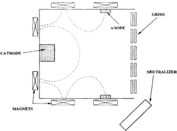
Hall thrusters accelerate ionized propellant through an electrostatic potential, thereby ejecting ions at high speed and producing thrust by reaction. A schematic of a generic Hall thruster is shown in Fig. 2-1. Ionization of neutrals relies on collisions of neutrals with the electrons. Electrons are emitted by the cathode as they enter the ionization zone where they are trapped in the magnetic field preventing them from streaming directly into the anode. Through collisions and turbulent scattering, both primary and secondary electrons can penetrate the magnetic field lines towards the anode, sustaining the ionization discharge. A potential difference externally applied between the anode and the cathode produces an axial electric field. The two fields set in mutually perpendicular directions result in an electron E x B drift motion in the azimuthal direction, perpendicular to both the electric and the magnetic fields. The ev x B force on the electrons due to this drift balances the electrostatic force on them, and the corresponding reaction on the magnetic assembly transmits the thrust to the body. This is the origin of the generic "Hall Thruster" designation for this device.
2.2.2 Ionization efficiency
The Hall thruster technology has by now reached its maturity and over the course of the past 20 - 30 years individual thruster assemblies have been experimentally
optimized with respect to the various configurations and operating regimes. It is, therefore, desirable to preserve these optimum characteristics (e.g. specific impulse and efficiency) under scaling. This can be accomplished by identifying the relevant
MAGNEFS
I CAHoDE
Figure 2-1: Hall thruster schematic
parameters that govern their physics and enforcing them to remain constant under scaling. All the basic plasma characteristics in gas-phase ionization devices rely heav-ily on the ionization process, whereby the neutrals are ionized in collisions with the electrons. As the size of the device is reduced, all else remaining constant, the number of collisions that the electrons and the neutrals experience with each other as they traverse the effective length of the device is reduced. Thus, in order to maintain the effective collision probability, it is necessary to increase the number densities of all the species in proportion. Equivalently, the mean free paths of the species between the consecutive collisions must scale with the characteristic length of the device:
A
Vn, 1h = =(
)
1 (2.1)L ceQ nL
where A is the mean free path, n is the particle number density,
Q
is the collision cross-section, L is the characteristic size of the device, vn and ce are the thermal velocities of the neutrals and the electrons respectively. It was shown in Ref. [4], that the electron energy equation is consistent with the assumption that the electron temperature is constant and independent of scale, hence ce must remain constant (refer to Appendix A for additional details). Therefore, the number density can be written as:n (2.2)
indicating that at constant h the number density n must scale inversely with size, as expected. Incidentally, surface erosion rates of the thruster components exposed to the ion beam are proportional to the ion flux into the wall which scales in propor-tion with the ion number density. Therefore, the expected life of exposed thruster components would scale as the ratio of the characteristic thickness to the erosion rate:
Tife ~ - L2h (2.3)
n
Existing 1.35 kW Hall thrusters have undergone laboratory lifetime tests and have demonstrated a maximum life of just over 7, 000 hrs. Thus, a ten-fold reduction in operating power would already decrease the theoretical operating life to only 70 hours. It is the lifetime limitation that makes miniature gas-phase ionization thrusters impractical for most long-term missions (unless scaling and performance are relaxed, as discussed in Sec. 4.5). The on-board power processing equipment is generally dominated by the weight of the solar array whose weight scales as the array area
(L2). Since the thruster mass, which scales as L3, becomes less and less dominant in comparison to the power processing equipment at small scale, the overall lifetime can be improved by introducing a system of redundant thrusters. In addition, properly chosen materials and magnetic field configurations can reduce the erosion rates and improve lifetime even further. A graphical summary of these scaling arguments and their consequences is schematically shown in Fig. 2-2. The lines of constant plasma density are shown as hyperbolas of the form n = 1/Lh. It can be seen that, although the lifetime generally suffers at small scale, additional improvements are possible at small values of L by compromising on the invariance of the scaling ratio h.
2.2.3
Confinement of electrons
Under the influence of an applied electric field, electrons emitted by the cathode are free to migrate towards the anode, in which case their residence time in the ionization region would not be sufficient to produce ionizing collisions with neutrals and sustain ionization. An external magnetic field is generally employed for the
h
nL=const
h=const
Life
L
Figure 2-2: Scaling of plasma density
purpose of trapping the electrons so that they can spiral around the magnetic field lines, thus increasing their residence time within the chamber. The ratio (f) of the Larmor radius to the thruster dimension can be used as a quantity characterizing the effectiveness of such a confinement scheme (refer to Appendix A for details). For adequate confinement
f
must be much smaller than unity. In fact, typical values off
in the existing Hall thrusters range anywhere between 0.008 and 0.01. The quantityf
can be expressed as follows:TL (MV) 1
f
TL(T BVL (2.4)To preserve
f
under scaling the strength of the magnetic field must vary inversely with length:B (2.5)
L f
This result indicates that, in order to maintain sufficient confinement of electrons, stronger fields are required at small scale. Existing 1.35 kW Hall thrusters operate at a magnetic field strength of 0.02 T. Keeping
f
constant, a thruster with a ten-fold reduction of power would require a field strength of 0.2 T. The following section addresses the feasibility of creating such magnetic fields and discusses the options available to do so.2.2.4
Magnetic confinement schemes
Most of the existing Hall thrusters in the power range between 200 W and 5 kW utilize electric coils to produce the required magnetic field. Ion engines, on the other hand, due to their intrinsic geometry generally use permanent magnets. It is interesting to first examine whether electric coils are still practical at small scale. To do so, consider a simplified model of a magnetic circuit with a narrow gap g driven by a coil with N turns and carrying a constant current I. The strength of the magnetic field produced within the gap is given by the following relation:
B
N
(2.6)9
Since g is proportional to L and B scales as 1/Lf, the product IN must scale as
1/f. Although it is not always the case, it is useful to assume for the purposes of
the current discussion, that most Hall thrusters use their main discharge current to drive the magnets. The discharge current I can be determined as the product of the current density times the area of the device:
L
I ~ jL2~ nL2 ~ -h (2.7)
Suppose, for simplicity, that h is kept constant. Then, I - L and N ~ 1/Lf. The
coil resistance scales as the total wire length NL divided by the cross-sectional area of the wire L2
/N,
so that:N2 1
R ~-- ~ L 2 (2.8)
L LPf 2
The power dissipated as heat is given by
Q
= 12R. In steady stateQ
must be conducted out to the surroundings, therefore,Q
~ ATL or:1
AT ~ (2.9)
L2f 2
This result suggests that if the temperature of the coils in a large thruster is elevated
f
fL=const
SI L
Bma T
Figure 2-3: Scaling of magnetic confinement schemes
would create a temperature elevation of 250 degrees ! It is, therefore, quite clear that electric coils are not suitable for miniature devices. The strongest existing permanent magnets, on the other hand, (such as SmCo alloys) are capable of producing magnetic fields on the order of 1 T. It is that figure of merit, representing the maximum achievable magnetic field strength, that limits the scalability of gas-phase ionization devices. A generic representation of the scaling for the magnetic field is illustrated in Fig. 2-3. The lines of constant magnetic field strength are hyperbolas of the form B = 1/Lf. The lines of constant AT are also hyperbolas of the form AT2 = 1/Lf.
The dotted line represents an upper temperature limit beyond which electrical coils are no longer practical. The boundary on the left-hand side is the field strength limit beyond which no known magnet exists that can produce the required field and beyond which scaling at constant
f
is no longer feasible.2.2.5
Performance analysis
It is the purpose of this section to utilize the previously developed scaling relations to discuss the scalability of thruster efficiency and specific impulse. As a result, it may be possible to infer the limitations of the attainable performance of Hall thrusters at small scale in comparison to the competing technologies.
An axial electric field created between the anode and the cathode imparts ki-netic energy to the ions ejecting them at high speed. Their exhaust velocity can be
determined by applying conservation of energy:
I2eV
C = e(2.10)
where mi is the ion mass, and V is the applied voltage. Clearly, in order to preserve the specific impulse, it is necessary to keep the applied voltage constant. The thruster efficiency can be determined as the ratio of the useful beam power to the input power in the form:
mc2
21V (2.11)
where rm is the mass flow rate, I is the anode current, V is the applied voltage, and c is the exhaust speed. Since the flow rate scales as the product of the plasma density and the area nL2 while the current scales with L, the efficiency must scale as:
nL2
~L ~ (2.12)
and, therefore, remains constant. It has been shown [4] that the major loss mecha-nisms associated with recombination of ions at the walls, radiation losses, as well as the propellant utilization mila/e all scale in proportion to the characteristic dimen-sion L, confirming that the obtained efficiency must, indeed, be independent of scale. The analysis of some of the relevant loss mechanisms is presented in Appendix A. Incidentally, currently existing 1.35 kW Hall thrusters have demonstrated efficiencies on the order of 50 - 55%. It is, therefore, conceivable that a miniature Hall thruster
could be built to operate at an Ip of 1,600 sec with a comparable efficiency.
2.3
Ion Engines
2.3.1
Principles of operation
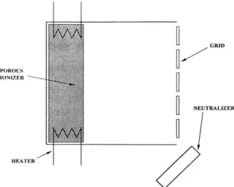
In their standard configuration ion engines accelerate ionized propellant through a set of extractor grids expelling ions at high speed and producing thrust by reaction.
GRIDS
- ANODE
CATHODE
NEUTRALIZER
MAGNETS
Figure 2-4: Ion thruster schematic
distinction in the configuration of ion engines compared to that of Hall thrusters is that ion engines make use of a set of grids to accelerate ions and, therefore, require an additional power supply to sustain ionization discharge and another power supply to heat the cathode filament which emits electrons within the ionization chamber. Due to this additional complexity, ion engines are generally considered inferior to the Hall thruster, even though, because of the larger operating voltages, they usually demonstrate efficiencies 5 - 10% higher than the Hall thrusters.
Although the scaling analysis for ion engines is similar to the one performed for the Hall thrusters, it is worth developing the model from first principles. It will be shown shortly that, unlike the geometry of Hall thrusters, the grids of an ion engine do not scale geometrically with the ionization chamber. For that reason, the overall configuration of a miniature ion engine needs to be revisited and the invariance of certain characteristic quantities, in general, can not be automatically assumed.
2.3.2
Confinement of neutrals
The geometry of a typical ion engine is such that the neutrals are free to escape from the ionization chamber through the grid holes without encountering any ionizing collisions with the electrons. In order to ensure that a sufficient percentage of the neutrals are ionized, it is necessary for the residence time of the neutrals within the ionization chamber to be much longer than the mean time between ionizing collisions.
The residence time of the neutrals within the ionization chamber is given by:
t min, nV (2.13)
tres =(.3
where n, is the density of neutrals, r is the flow rate of neutrals, and V is the volume of the ionization chamber such that V = AL where A is the cross-sectional area of the device and L is the chamber length. The mass flow rate of neutrals escaping through the grid holes can be expressed in terms of the effective open area fraction
(transparency ratio)
#n
as follows:mn- m- in An (2.14)
On the other hand, the mean time between the ionizing collisions is given by:
1 _ 1
t - - - 1(2.15) vi neCeo~i
where ne is the electron density, ce is the mean thermal velocity of the electrons, and
oi is the ionization cross-section. In order to ensure that at least one ionizing collision
occurs during the time that a neutral particle resides within the ionization chamber,
tres must be greater than ti, or:
4LrieCeOi> 1
(2.16)
cn#,n
Disregarding quantities which are independent of scale (assuming Te is invariant), the above equation reads as follows:
~eL const
(2.17) If
#n
were to remain constant, the latter relation for the number density would be consistent with the one obtained earlier for the case of Hall thrusters.2.3.3 Confinement of electrons
Although the idea of scaling the Larmor radius in proportion to the size of the device is still applicable, the cusped geometry of the magnetic field lines permits the additional freedom of placing the anode such as to allow an appropriate proportion of electrons to be captured. Just as in the case of the analysis for the neutrals, it is useful to examine the relative magnitudes of the mean time for a primary electron to encounter an ionizing collision and the mean diffusion time of such an electron across the magnetic field lines. The mean time for a primary electron to ionize a neutral is given by the following relationship:
t = 1 (2.18)
nn lVP ai
where vP is the mean velocity of primary electrons. Assuming Bohm diffusion to be the dominant transport mechanism, the mean diffusion time for a primary electron is given by:
L 2 16eBav
tdif5 ff2 A ae (2.19)
A kTe
where Bave is the effective magnitude of the magnetic field within the region where
electrons reside while diffusing towards the anode. A dimensionless geometrical factor
f has been introduced to account for the relative location of the anode with respect
to the magnetic poles (large
f
when the anode is "between cusps", smaller when itis directly in line with one). Larger values of f are equivalent to a reduction of the
diffusivity A, hence, yield a longer time for an electron to diffuse to the anode. For
sufficient utilization of the primary electrons tdiff must be of the same order as ti, or:
f2 ABavenn ~ 1 (2.20)
Since the input power scales with nA, one can rewrite the above relation as follows:
With the exception of an additional geometrical factor
f,
this result is identical to the one obtained earlier for the scaling of the magnetic field in Hall thrusters. In this case, however, additional flexibility is offered by allowing the appropriate placement of the anode to draw just enough primary electrons to sustain ionization discharge. It should be noted, however, that if the effective Larmor radius is chosen to be of the same order as the dimension of the ionization chamber or less, most of the electrons would be rapidly drawn towards the anode irrespective of its position. Hence, ion thrusters, just as the Hall thrusters, suffer from a similar lower bound on the size determined by the maximum attainable magnetic field. Taking the mean field to be on the order of 0.1 Tesla, the corresponding minimum chamber size for which the electrons are still sufficiently confined is about 1 - 2 mm. The currently existing models of ion engines already utilize magnets which produce magnetic fields on the order of 0.1 - 0.2 T. It may, therefore, be difficult to achieve large reduction in size and power without sacrificing electron confinement characteristics. One way to partially offset this complication is to make the magnets proportionally larger as the chamber size is reduced. In such a case, the region occupied by the electrons will be disproportionately closer to the magnetic poles resulting in concentration of the field strength at that location and, therefore, improving the confinement efficiency. Conclusive analysis of such a scheme, however, requires detailed numerical modeling and will be avoided for the purposes of this preliminary analysis.2.3.4
Scaling of the ion optics
Most of the existing models of ion engines utilize an extractor grid with a large number of holes sized in such a way as to be no larger than twice the characteristic Debye length. Had the holes been larger in diameter, the electrodes would have been completely shielded by the sheath and the ions would have been free to escape from the ionization chamber without undergoing any acceleration. Although smaller holes are acceptable as well, manufacturing these introduces unnecessary fabrication/assembly difficulties and is usually avoided. Following this logic the expression for the hole size
can be written as
CokTe eV *
dh =2 (2.22)
e2nen. kTf/
Since the plasma density scales inversely with L/$4, the hole diameter would scale as:
dh ~ (2.23)
This result indicates that the holes become larger in proportion as the size of the device is reduced and, thus, fewer holes will be needed in a smaller grid:
D2D2
Nh D On D nL (2.24)
hd
It is, therefore, plausible that a small enough chamber could be built such as to require only one hole. Just for the purposes of illustration, one such design would consist of a 2 mm long chamber with a transparency ratio @ of 0.2, the resulting hole size of 1
mm, and the corresponding chamber diameter of 2.3 mm.
As it was mentioned earlier, grid spacing does not scale photographically with the rest of the structure. A scaling relation for the grid spacing can be obtained by examining the current density limited by the effects of the space charge:
V3/2
j (2.25)
Since the current density
j
is proportional to the plasma density, which scales as 1/L, at a given voltage V grid spacing varies as:d ~ v'L (2.26)
indicating that the grid spacing becomes proportionately larger at small scale. This result is of no major consequence to the overall thruster design, other than the fact that it may alleviate some of the manufacturing difficulties associated with the pro-duction of grids in comparison to their larger counterparts for which grid separations are already on the order of 1 mm.
ELECTRIC COIL
PLASMA
RINGS
Figure 2-5: PIT schematic
2.4
Pulsed Inductive Thrusters
2.4.1
Principles of operation
High power Pulsed Inductive Thrusters (PITs) have been originally introduced in the 1960's, however, since then have not received much attention. PITs accelerate propellant away from its walls, hence, unlike miniature Hall and ion thrusters, PITs may not suffer from intensified erosion rates and degradation of life and, along with their controllability advantages could be promising for micro-satellite applications.
PITs operate by injecting puffs of gas over a coil which is subjected to a set of periodic current impulses (see Fig. 2-5). The time varying magnetic flux produces a circulating electric field within the gas causing an electrical breakdown to occur. The resulting plasma ring carrying electrical current is magnetically accelerated away from the coil producing thrust transmitted to the coil by reaction [5].
2.4.2
Loss mechanisms and scaling
Two major loss mechanisms have been identified in the operation of PITs - those due to shocks and those due to Ohmic losses in the plasma ring. Shock losses arise from the well-known "snow-plow" effect [5], whereby the region of gas located further away from the coil is unable to ionize as it is partially shielded by the self-field of the plasma ring created in close proximity to the coil. The ionized ring accelerates through the remainder of the neutral gas, resulting in heavy dissipation. Ohmic losses in the
plasma ring, on the other hand, arise due to the finite conductivity of the plasma. It has been shown in Ref. [5] that the characteristic thickness of the plasma ring scales in proportion to the square root of the thruster dimension, indicating that a thicker
layer of gas can be ionized and accelerated as the size of the device is reduced. In
fact, a device 1 cm in diameter would produce a plasma ring whose thickness is of the same order as the gas layer itself. It can, therefore, be argued that shock losses will have either minimal impact on the thruster performance or be completely eliminated at small scale. Ohmic losses, however, exhibit less desirable characteristics. These losses can be estimated by determining the ratio of the induced electric field due to the variation of magnetic flux in time to the electric field due to Ohmic resistance in the plasma:
Rm = E (2.27)
Eo
The quantity Rm is known as the magnetic Reynolds number which indicates the rel-ative importance of resistive losses in the induction-driven accelerators. The induced
electric field generally scales with the motional EMF which is given by:
Ej = v.B, (2.28)
where v, is the velocity of the ring and B, is the magnetic field, while the field in the
plasma ring can be determined from:
E0 = - (2.29)
where
j0
is the azimuthal current density in the ring and o is the electrical conductivityof the plasma. The current density
jo
can be determined from the Ampere's law:or, written for the azimuthal component of the current:
1= - ~ ~ -- (2.31)
YtO 1Z P~oZ
Substituting the above relationships into the expression for Rm one has:
Rm = /IoVZ (2.32)
The quantity z can be interpreted as a characteristic size of the plasma ring, while the electrical conductivity of the Coulomb dominated plasma is given by:
e
(2.33)
meceQei
The speed of the ring v which determines the Ip of the device as well as the quantities appearing in the expression for o are independent of scale. Since z /15, where D isD
the characteristic size, the magnetic Reynolds number will decrease as the size of the device is reduced, resulting in the relative increase of Ohmic losses and degradation of efficiency. To put this argument in perspective, Ref.[6] reports a PIT (1 m in diameter) operating at an average power of 100 kW PIT (assuming 10,000 to 1 duty cycle) which has successfully demonstrated efficiencies on the order of 50 - 60% and
an I, of 3,000 - 6, 000 sec. The magnetic Reynolds number Rm for this device was on the order of 100, indicating that resistive losses were negligible in comparison to the operating power. On the other hand, a 1 cm device operating at 10 kW under similar conditions would yield a Reynolds number Rm on the order unity, indicating that a sizable fraction of the power coupled into the plasma by induction would be dissipated as heat. It is this intrinsic limitation of the induction devices in general that makes them impractical at power levels below about 10 kW.
GRID
POROUS IONIZER
NEUTRALIZER
HEATER
Figure 2-6: Schematic of a contact ionization thruster
2.5
Contact Ionization Thrusters
In the quest for a more durable device that could operate at low power yet provide sufficient operating life to be of practical interest, contact ionization thrusters were considered for miniaturization. They do not rely on collision-based ionization, hence do not require the usual increase in the plasma density to counter the reduction in size. Although erosion is intrinsically unavoidable, it is anticipated that these thrusters are less likely to suffer from quadratic decrease in operating life and, thus, become excellent candidates for miniaturization.
2.5.1
Principles of operation
It was originally proposed and later demonstrated by Langmuir that a heated surface of a metal with high electron work function
#e
immersed in a vapor of an alkali metal, whose ionization potential#2
is lower than#e,
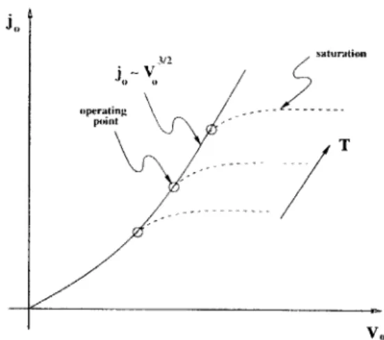
would convert some of the alkali atoms into positive ions. These ions can be electrostatically accelerated to high speeds producing thrust by reaction similar to the operation of a typical ion engine. The schematic of a contact ionization thruster is shown in Fig. 2-6.Existing models of contact ionization thrusters normally consist of a porous tung-sten ionizer heated to temperatures on the order of 1, 200 -1, 400 K and utilize cesium as a working fluid. Any surface contamination lowers the work function of the ionizer and seriously impairs its ability to ionize the propellant. High ionizer temperatures
are, therefore, necessary to help evaporate alkali particles off of the surface and main-tain adequate ion production in steady-state. Too high a temperature, on the other hand, enhances thermionic emission of electrons from the cesium absorbed on the surface, partially neutralizing some of the ions and reducing the resultant ion current density. This suggests the existence of an optimum operating temperature at which maximum ion current density can be extracted.
2.5.2
Scaling of contact ionization thrusters
Just as in the case of ion engines, the resultant current density extracted by the electrodes is limited by the space charge and can be modeled by the Child-Langmuir equation:
V3/2
jo 2 (2.34)
X0
where V is the extractor voltage and xO is the spacing between the ionizer and the negative electrode. As the extractor voltage is first increased from zero, the current density follows the Child-Langmuir law until it asymptotes to a value dependent upon the ionizer temperature. Higher temperatures generally enhance cesium evaporation rates and yield larger saturated current densities as illustrated in Fig. 2-7. Since any accumulation of ions at the ionizer site would contaminate its surfaces and degrade utilization efficiency, it is desirable to operate these devices at the onset of saturation, i.e. at such voltages for which all or most of the ions produced by contact ionization are extracted in the steady state. Since the power extracted by the jet is proportional to the current density, it is desirable to keep the current density high so that the radiative losses remain a small fraction of the total input power. As expected, the major loss mechanism in contact ionization devices is thermal radiation from the heated ionizer surfaces. The radiated power is governed by the Boltzman radiation law which scales as:
PIOSS ~ o-eT 4 L2 (2.35)
where T is the ionizer temperature and L is the characteristic thruster dimension. The useful power extracted by the jet in the form of kinetic energy can be determined
jI" 3/2 j" V saturation T v.
Figure 2-7: Current density vs. temperature for cesium-tungsten configuration from the following relation:
Pi(et
~ jo(T)VnL2 (2.36)where jo (T) is the saturated current density and V, is the net accelerator voltage.
Suppose that operation at constant voltage is desired. From Eqns. 2.35 and 2.36 it is
clear that both the jet power and the radiative losses scale with L2
. Thus, their ratio
and, therefore, the efficiency, will remain constant. However, since xO must remain constant as well, in order to achieve the desired reduction in power the diameter of the
device L must be reduced. The resultant device will become proportionately longer
and thinner. Although the losses of ions to the wall in larger devices are generally
negligible in comparison to the radiative losses, they may become significant for this disproportionately scaled configuration. The power lost to the wall scales as the product of the ion flux and the surface area of the side wall. Since the voltage remains constant, particle flux is proportional to the current density. Therefore:
Pwalu ~ jo(T)xoL (2.37)
Clearly, the power lost to the wall falls off slower than the jet power with decreasing
L, hence, it is possible that for sufficiently high aspect ratios xo/L wall losses will
dominate over the radiative losses and the efficiency will no longer remain constant. An alternative scaling strategy is possible for which the aspect ratio is preserved,
Intro-ducing a scaling parameter
f
to indicate the reduction of operating power, such thatf
~jo(T)L
2V, the operating voltageV
can be expressed in terms of the operatingpower. Since jo(T) depends only on the ionizer properties and is independent of scale, the extractor voltage V must scale as:
Vo ~ L 4/3 ,f2/5 (2.38)
The overall efficiency can now be evaluated as the ratio of the jet power to the total input power:
Piet 1
Piet +Poss 1+ ioV2 (239)
Just as in the case of ion engines, in order to preserve the shape of the ion beam and maintain minimal beam divergence, the ratio of V, to V must remain constant. In this case the efficiency would scale as:
_1 1
r/ ~(2.40)=
1(+ "eT()
1+
K 30V %where K scales as T4
/joL
4/3 or, alternatively as T4/jof 2/s. As the size of the deviceis reduced at constant
jo
and T, the ratio of radiated (lost) power to the beam power is increased in proportion to 1/f 2/1, indicating a reduction of efficiency at small scale.In order to evaluate the impact of these losses it is useful to examine some of the existing devices and compare their efficiencies to those obtained for the proposed smaller models operating at lower power. Ref. [7], for instance, supplies a detailed set of experimentally measured data for a cesium-operated linear contact ionization thruster. A thrust of 1.37 mN was obtained at an Ip of 6, 700 sec and the total input power of 105 W yielding an efficiency of 45%. Using the above definition for K this value of efficiency corresponds to K = 1.22 indicating that radiative losses are of the same order as the useful power carried by the jet. Reduction of jet power
by a factor of 10 would yield size reduction by a factor of 2 (from
f
~ joLi0/3) witha disproportional increase of radiative energy losses corresponding to K = 3.07 and
reduction of power, specific impulse which scales with the square root of the applied voltage or, alternatively, as L2/3
or
f
1/5 yields a favorable decrease from 6, 700 secto 4, 220 sec. Since many near-Earth missions of practical interest optimize at much lower values of Ip, additional reduction of size and power would be desirable, however, any further miniaturization would result in unacceptable energy losses.
One possibility for mitigating such a dramatic drop in the efficiency is to reduce the operating temperature of the ionizer. Since radiative losses generally scale as T4 and, thus, are very sensitive to variations in T, it is conceivable that propellant
utilization and
jo
can be sacrificed to a limited extent for additional gain in the overall efficiency. It is expected, however, that under such circumstances the quantity T4/jo, which was previously assumed to depend only on the ionizer characteristics and remained invariant, could be reduced by a proper choice of operating temperatures and/or alternative ionizer configurations. Asjo
is reduced from its optimum value, however, possible gains in the overall efficiency may be offset by the degradation of propellant utilization, eliminating any practical benefit of this approach.It should be pointed out that although the efficiency of contact ionization thrusters does suffer at small scale, a 10-Watt device operating at 24 % efficiency is quite an attractive alternative in comparison to the existing PPTs, which can operate at similar power levels, yet demonstrate efficiencies of only 7-10 %. There is one drawback, however, which makes contact ionization thrusters inferior to many other technologies. The use of highly reactive and corrosive propellants, such as cesium, significantly complicates storage, handling, and operation of these thrusters on board of a spacecraft. A more detailed discussion of the handling issues can be found in the Summary section of this chapter.
2.6
Colloidal Thrusters
Colloidal thrusters are representatives of yet another technology of electrostatic accel-erators which does not rely on ionization in the gas phase and, hence, their operating life is not compromised at small scale. In addition to their intrinsically small