A Demonstration of a Formal Specification & Requirements Language: A Case Study
by
Sean J.P. Sutherland
Submitted to the Department of Electrical Engineering and Computer Science in fulfillment of the Requirements for the Degree of
Masters of Electrical Engineering and Computer Science at the Massachusetts Institute of Technology
August 31, 2001
Copyright 2001 Sean J. P. Sutherland. All rights reserved.
The author hereby grants to M.I.T. permission to reproduce and distribute publicly paper and electronic copies of this thesis
and to grant others the right to do so.
Sean J. P. Sutherland Department of Electrical Engineering and Computer Science August 31, 2001
I
Professor Nancy G. Leveson Thesis Supervisor
ArthmnuaTh Chairman, Department Committee on Graduate Theses
MASSACHUSETTS INSTITUTE OF TECHNOLOGY
JUL
3 1 2002
Certified by Accepted by Cuthorlawly,451,
Demonstration of a Formal Specification & Requirements Language: A Case Study
by
Sean J.P. Sutherland
Submitted to the Department of Electrical Engineering and Computer Science in fulfillment of the Requirements for the Degree of
Masters Of Electrical Engineering and Computer Science at the Massachusetts Institute of Technology
August 6, 2001
Abstract
This document provides a demonstration of the application of Specification Tools and Requirements Methodology Requirements Language, SpecTRM-RL, to a component of an Air Traffic Control System called Sector Handoff. SpecTRM is a formal specification and requirements language that allows designers to incorporate safety concerns into their design process, paying particular attention to issues of human-machine interactions. SpecTRM is uses the concept of means-end hierarchies to achieve traceability in both directions between its five levels of specification. Although this example only uses three of the five levels in SpecTRM-RL, it is complete with tracings of requirements to lower levels of the specification. The Sector Handoff function used is part of Raytheon's Standard Terminal Automation Replacement System (STARS).
Thesis Supervisor: Nancy G. Leveson
ACKNOWLEDGEMENTS
I would like to express my sincerest appreciation to my thesis advisor, Professor Nancy Leveson of the Massachusetts Institute of Technology, and Jeffery Levine of Raytheon
TABLE OF CONTENTS
Introduction
15
Related Work
19
Background
22
Aerospace Accident Factors
22
The Goal of Intent Specifications
25
Intent Specification
29
Sector Handoff
31
Analysis: Intent Specification for Sector Handoff
37
Level I
39
Level II
46
Level III
84
Conclusion
102
Appendix A: Future Work
103
Appendix B: List of Abbreviations and Definitions
105
LIST OF FIGURES
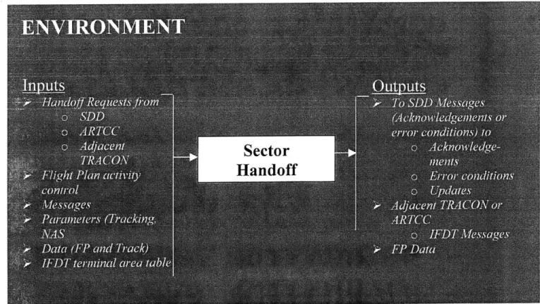
Figure 1: Diagram of Environment 46
Figure 2: Diagram of System Environment 84
LIST
OF TABLES
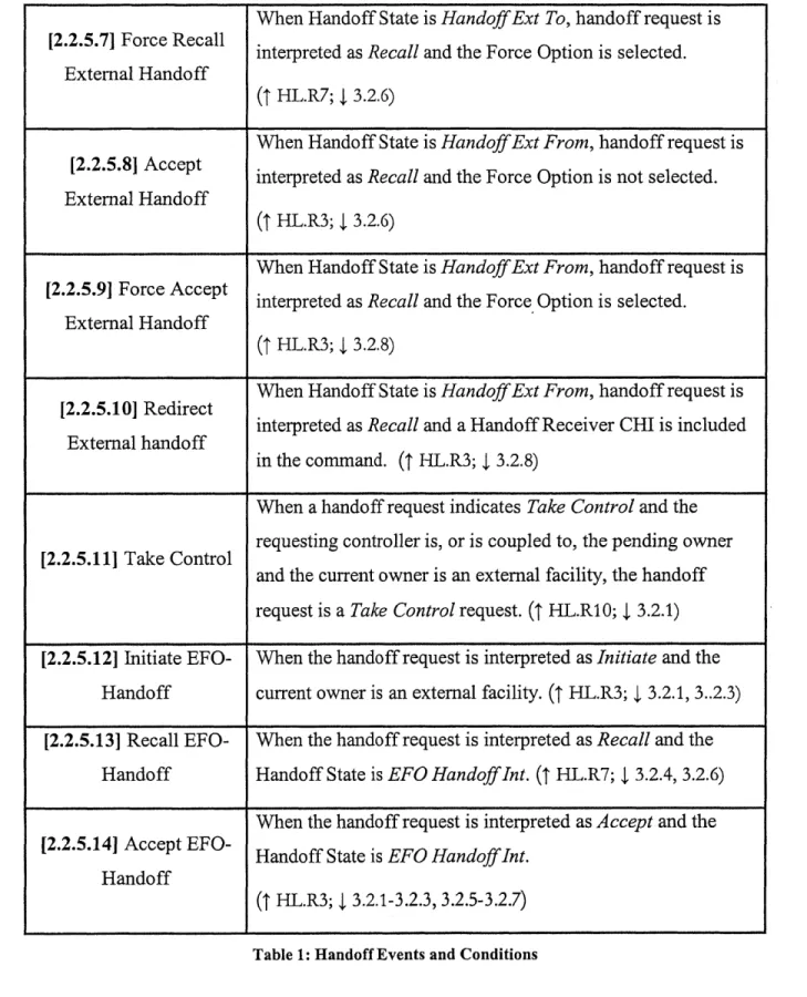
Table 1: Handoff Events and Conditions
52
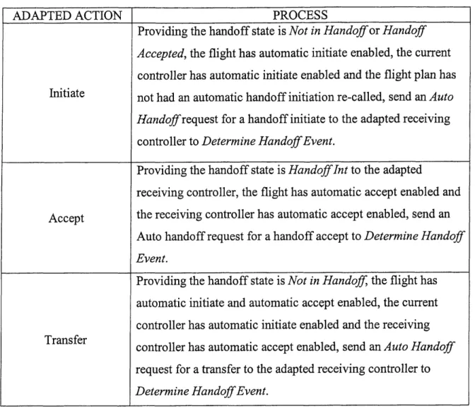
Table 2: Handoff Actions
81
Table 3: System Messages
86
Table 4: Initiate Handoff (Implied command)
87
Table 5: Recall Handoff (Implied command)
87
Table 6: Accept Handoff (Implied command)
88
Table 7: Take control of interfacility track (Implied command)
88
Table 8: Inhibit automatic handoff for a flight (Implied command)
88
Table 9: Accept handoff
88
Table 10: Initiate intrafacility handoff
89
Table 11: Initiate handoff to ARTCC
89
Table 12: Initiate NAS FP handoff to adjacent Tracon
90
Table 13: Initiate local FP handoff to adjacent Tracon
90
Table 14: Recall handoff
91
Table 15: Redirect incoming interfacility handoff
91
Table 16: Inhibit automatic handoff for a flight
92
Table 17: Current State
=
Not in Handoff
92
Table 18: Current State
=
Handoff Initiate Pending
94
Table 19: Current State
=
Non-Enroute FP Pending
94
Table 20: Current State
=
Non-Enroute CX Pending
94
Table 21: Current State
=
Outbound HO Accepted
95
Table 22: Current State
=
Handoff Ext To
95
Table 23: Current State
=
Handoff Recall Pending
95
Table
25:
Current State
=
Handoff Accept Pending
96
Table 26: Current State
=
Inbound HO Accepted
96
Table
27:
Current State = Handoff Int
96
Table 28: Current State
=
Local HO Accepted
97
Table 29: Current State
=
EFO Handoff Int
97
INTRODUCTION
Recent advances in computer technology have driven engineers to increasingly incorporate computers into their systems. Many engineers now place complex control capabilities in the hands of software running on these computers under the impression that it is "easier" to modify code to add or modify functionalities than it is to change the hardware. However, this is not as simple as it appears. Research shows that the increased computerization of systems has made the systems far more complex and has resulted in more unexplainable system behavior. These failures are at the system level, as it is not the faulty software that causes the damage, but the instruments and hardware the software controls. [1] For systems where the software becomes critical to the safe operation of the
system, software failures may lead to loss of human life and property.
The increase in automation, coupled with a decrease in physical interlocks, has made it even more crucial that software interacts safely with the rest of the system to
avoid catastrophic outcomes. Formal Specification Languages are needed to help ensure that errors are eliminated from the software. However, Intent Specification Languages improve upon Formal Specification Languages as they additionally incorporate humans in the design process. This means that human psychological and physiological principles
are used are guidelines in determining how one should design a system. [2] Intent specification languages, unlike formal specification languages, capture the rationale and assumptions made while humans set out to solve problems. This allows for traceability in the system as high-level requirements can be traced to the actual system implementation details, and vice versa. This also allows for safety critical design decisions to be enforced
on the low-level implementation, such as software.
Intent specification uses a three-dimensional model to analyze a system. In the intent dimension, there are five hierarchical levels: system purpose, system principles, black box behavior, design representation, and physical representation (code). Each of
directions. A second dimension, called the refinement dimension, allows one to create several design states or steps. The third dimension, the decomposition dimension, allows system designers to define boundaries such as the environment, operator, system and system components. [2]
Safeware Engineering Corporation [3] has developed an experimental toolset called Specification Tools and Requirements Methodology Requirements Language,
SpecTRMRL. This Intent Specification tool is part of ongoing research into formalizing and testing methodologies for completeness in complex software systems, spearheaded by Professor Nancy Leveson. SpecTRM addresses completeness issues including
completeness with respect to mathematical theory and formal logic, and also with respect to cognitive engineering. SpecTRM attempts to establish solid design principles by working from the ground up and paying particular attention eliminating hazards from the design and incorporating Human-Machine Interface guidelines. SpecTRM also allows system designers to ensure the requirements are traced to all levels of their design. Traceability and human centered design guarantee SpecTRM's ability to contribute to creating safer designs.
The design of SpecTRM has three important objectives. The first is to determine important goals for specification languages based on experience with industrial
applications. The second is to generate hypotheses about how these goals might be accomplished. The third is to make these hypotheses functional elements in the language. After the first versions of SpecTRM, the designers have come up with new concerns.
Some of these include enhancing readability, eliminating error prone features, such as internal broadcast events, writing pure black box specifications, and allowing reuse and specification of program families. [4] This thesis uses the SpecTRM Version 2.3, to model one module of Raytheon's Standard Terminal Automation Replacement System (STARS).
STARS is an air traffic control system designed by Raytheon, and is responsible for managing terminal area airspace for both the FAA and the Department of Defense.
STARS can track up to 1350 airborne aircraft simultaneously within a terminal area. The system interfaces with multiple radars, 128 controller positions, 20 remote towers, and a 400 by 400 mile area of coverage. It comprises four functionally different systems: a STARS Central Support Complex (SCSC), nine Operational Support Facilities (OSFs), 9 Operations Control Centers (OCSs) and 311 Operational Sites.
The SCSC is located at the FAA Technical Center and provides for software development, testing, and field support. An OSF provides an environment that controls upgrades and modifications to the Operational Sites. It is responsible for distributing software and adaptation data to the STARS Operational Sites. Each OCC is associated with up to 80 STARS Operational Sites. It is responsible for Remote Monitoring and Control (RMC) of the associated Operational Site, and gathers and records performance data. An Operational Site has several computers connected by a dual Local Area Network (LAN) that accepts radar and flight plan data and displays aircraft movements on the Terminal Display Workstation and the Terminal Controller Workstation screens.
The goal of the air traffic control (ATC) system is to satisfy and balance the two critical goals: safety and efficiency. Human participants in the system must make . continuous adjustments in flight scheduling and flight paths to maximize efficiency without compromising safety. The many redundant components in the system, and the
smooth communications between its operators (both on the ground, and between ground and air) have generally allowed the ATC system to recover gracefully from failures, without accident. Because perfect system reliability can never be assumed, it is important that planners not change the ATC system in ways that will destroy these critical failure-recovery aspects.
Recently, many air traffic control functions have been automated, especially in the areas of sensing, warning, and information exchange. Generally, the attitude about these systems has been positive, but there is a concern that the human controllers lose
alertness and awareness of automated functions and system functioning, which may become critical if sudden manual intervention is necessary. More importantly, humans
may distrust the automation because they fail to understand its complexities, and it is possible that reliance on automation may lead to a loss of human proficiency in the skills that the automation replaces. [5]
This thesis will provide a SpecTRM model of a subsection of STARS called Sector handoff. Sector Handoff refers to a change in aircraft controller that occurs
whenever an aircraft is crossing the boundary between one controlling sector and another. [6] This thesis will also demonstrate that applying Intent Specification Languages, such as SpecTRM_RL can provide much more insight and lead to a safer design. This is a proof-of-concept demonstrating the power of SpecTRM Requirement Language. Seeing that STARS already exists, Sector handoff will only be modeled up to Level 3.
RELATED WORK
SpecTRM is a relatively new formal specification language and so there are few examples of it used to model existing systems. All of these models have been done by Professor Nancy Leveson herself, or by her students at the University of Washington and at the Massachusetts Institute of Technology.
TCAS II [7] Intent Specification, written by Professor Leveson and Jon Damon Reese, is the most expansive example of SpecTRM used to model a system. TCAS is an FAA developed airborne collision avoidance system that relies on analysis of aircraft's transponder responses to determine potential collision threats. The FAA also mandated that, as of December 30, 1991, TCAS II be standard equipment on every aircraft with more than 30 seats. The Intent Specifications for TCAS II described the system on all five levels of SpecTRM: System Purpose and Properties, System Design Principles, Black box Behavior, Physical and Logical Design Representation and Physical Implementation.
The Center TRACON Automation System (CTAS) was also modeled using SpecTRM. CTAS is a system that provides automation tools for planning and controlling arriving air traffic. CTAS generates air traffic advisories, which are aimed at increasing fuel efficiency, reducing delays, and providing automation assistance to air traffic
controllers. Sean Sandys, with the assistance of Michael Shafer, Jon Reese and Professor Nancy Leveson, built the SpecTRM-RL model for CTAS. This work is described in a paper titled "A Demonstration Safety Analysis of Air Traffic Control Software." [8]
The Altitude Switch is another example of a SpecTRM model. [9] However, it is an incomplete model and does not quite completely express the altitude switch at all levels of SpecTRM. The altitude switch example was taken by Professor Nancy Leveson from an already existing specification by Steven Miller at Rockwell Collins, and which was part of a draft paper titled "Modeling Software Requirements for Embedded Systems." [10] To Miller's specification, Professor Leveson applied the SpecTRM modeling using a different methodology to that used by Miller.
The Software Engineering Research Laboratory has been working on two projects that apply SpecTRM software to Air Traffic Control Systems. The first of these is a Medium Term Conflict Detection (MTCD) for Eurocontrol Experimental Center (EEC).
MTCD is a planning tool that will assist Controllers in identifying potential conflict situations. The goal is for early detection so that the controller has enough time to assess the severity of the situation and act accordingly to resolve the conflict. The conflicts that concern the MTCD system are aircraft conflicts, airspace conflicts, and descents below
lowest usable flight level (ground proximities). Unlike many of the already applications of SpecTRM, this system is not yet functional and so this is one application of SpecTRM to the design process.
The second project of SERL is to apply SpecTRM tools to Raytheon' Standard Terminal Automation Replacement System (STARS). SpecTRM is being applied to three modules of STARS. These modules are the Minimum Safe Altitude Warning (MSAW), Conflict Alert/Mode-C Intruder, and Sector Handoff Modules. This thesis will document the work done on the later module. In addition, William Melendez-Diaz has also created some guidelines to assist SpecTRM users and other intent specification users in
distinguishing between the five levels of the specification. This, from experience, has always been extremely difficult, and the guidelines in Melendez-Diaz's thesis, "The
Different levels of Intent Specifications: Analysis and Guidelines on Tracing," [11] will be invaluable to anyone working with Intent Specifications.
Professor Leveson has also incorporated the use of SpecTRM in her class on System and Software Safety at the Massachusetts Institute of Technology. This past spring (2001), the class assignments included creating intent specifications for the Disney Matterhorn Roller Coaster Ride. There was also some SpecTRM modeling of the ride.
BACKGROUND
This section explains the role of Intent Specifications in designing systems by first
examining the main factors that lead to aerospace accidents, describing the goals of Intent Specifications, and finally outlining the structure of an Intent Specification.
Aerospace Accident Factors
There are several factors that account for aerospace accidents. A recent study [12] by Professor Leveson and the Software Engineering Research Laboratory identified three systemic factors that have led to aircraft accidents. These are flaws in the Safety Culture, ineffective organizational structure and communication, and ineffective or inadequate technical activities.
Flaws in the Safety Culture
The Safety Culture of an industry refers to the philosophy of the people working in that industry towards ensuring that their work environment is safe and that the products they produce are able to operate safely when released. Like many other industries, the aircraft industry (though primarily focused on safety) is not without its share of flaws in its Safety Culture. There is overconfidence in automation that encourages the engineers to put the final authority in the automation rather than the pilot. For example, in Airbus aircraft, the pilot cannot disconnect the autopilot even if he applies force to the control wheel. Reports from the 1994 accident involving China Airlines A300 Flight 140 in Nagoya, Japan, recommend that Airbus considers design changes that would allow the autopilot to disconnect, and manual override functions so that crew can safely maneuver the aircraft if necessary. [12]
The commercial aviation industry is the first industry in which control of safety-critical functions by both humans and computers has been widely implemented. [12] This poses difficulty for the industry to quickly recognize and acknowledge problems
blame the pilot for the accident than it is to investigate aspects of the system design that may have led to the human error(s). [12] Similarly, when changes are made to the
automation, even if prompted by a previous accident linked to that design feature, it is not unusual for airlines to delay incorporating them into all their aircrafts. [12] This was a factor in two of the three aircraft accidents covered in Professor Leveson's paper, [12] where there was inadequate responses to prevent future loss when there are near misses and warnings. For example, in the Nagoya accident, modifications to the FMS were only recommended, as versus mandatory, and France did not issue an airworthiness directive (AD) to alert airlines to the flaw in the automation. [12]
Ineffective organizational structure and communication
Poor organizational structure and communication have led to information on many safety issues and concerns not being distributed to pilots. In the Nagoya accident, the flight crew had not been informed of similar incidents with China Airlines that had occurred prior to the accident. Also communication problems between crewmembers were cited as factors in the Nagoya accident, the 1993 accident involving Lufthansa Airbus A320 in Warsaw, Poland, and the 1995 accident involving American Airlines Flight 965, a Boeing 757-223, in California, USA.
Ineffective or Inadequate Technical Activities
The increase in the complexity of automated systems in the aviation industry has not been matched with adequate documentation of the intricacies of the design. Reports from the three accidents mentioned above noted this as a problem. [12] The Aircraft Operations Manual for the aircraft involved in the Warsaw accident contained inadequate,
conflicting, or poorly designed documentation of the automatic flight systems. The Nagoya reports identify unclear descriptions of the Automatic Flight System in the Flight Crew Operating Manual. In the California accident, there were discrepancies between the display of identical data on the approach charts and on the FMS-generated displays. [12] This lack of commonality can be confusing to pilots, thus increasing their workload at critical phases of the flight. [12]
In the design process, automation designers have limited cognitive engineering resources, as research in that area, particularly that is directed at the influence of software design on human error, is still in its early stages. However, there is Human Factors research and guidelines on making the most use of the operator's time without overloading him or her at critical periods of flight or boring him or her at less critical periods. There is also research that addresses human-machine interaction with emphasis on designing displays and keyboards. The accident in California was an example of task saturation and overload, which led to distraction from the appropriate behavior. [12] Also, Human Factors research also addresses the in which the pilots are given feedback (warnings and advisories) and its effect on the way in which they process and react to the information in a crisis. The research shows that if the pilot is bombarded with warnings during an emergency, he or she will not be able to decipher which warning is more important. [12]
Professor Leveson's paper also addresses the problem that pilots are having understanding digital automation as evident from accidents, surveys and simulator studies. [12] In the California and Nagoya accidents mentioned above, the flight crew's limited understanding of the automation were factors in the accident. Both accidents show that proficient use of the FMS without adequate knowledge of the underlying logic can lead to misuse. [12] The problem arises especially when the crew encounters controls and operations that are seldom experienced in a daily flight. Professor Leveson proposes simplification of the automation so that is understandable or new training methods can combat this problem. [12]
There is also evidence of inadequate use of System and Safety Engineering in the commercial aircraft industry. [12] The inadequacy leads to poor integration of system components: software and hardware, even though both are usually thoroughly tested independently. The Nagoya accident report mentions the lack of automated protection against or nonalerting of the pilots to unsafe states. In the California accident, the pilots were not alerted to the extension of the speed brakes. [12]The use of intent specifications
at this level will assist in system integration and allow for traceability at all levels. Intent specifications would also help designers and implementers to better understand the function of each component and their interactions. This should help improve usability of systems and completeness of user manuals.
The Goals of Intent Specification
Software that correctly implements an algorithm can become ineffective once introduced into a system. This phenomenon is exacerbated when humans are brought into the
system. In designing problem-solving paradigms for software, we must be mindful of the cognitive problem-solving process that occurs in the human user. Intent specifications are designed to enhance the designing process by making the human cognitive psychology, system theory, and human-machine interaction fundamental in shaping the evolution of the system design. Intent Specifications serve to integrate formal and informal aspects of software development. The formal aspect of software is limited to the mathematical and logical components. There are other non-mathematical aspects that need to be integrated into the design and Intent Specifications allow for this to happen.
Intent Specifications also improve our ability to engineer for quality and to build evolvable systems. [2] Using intent specifications allows essential system safety
properties to be built into the design from the outset of the design. This early planning allows for changes to be made at one level and to be traced to all levels of the design. The rationale behind design decisions is also captured and can be traced to design decisions
and implementations at all levels of the system. Design choice, based on human factors guidelines, can also be captured. Also, intent specifications help designers to achieve uniformity in the system.
The biggest advantage of Intent Specifications is that it offers system designers several ways to view the system, depending on what the designer is looking. This ability to abstract the system differently allows specific designers to ensure that their work
cascades to all levels of the system, and also that there are no conflicts in the system. Also, allowing designers different system abstractions helps them to do better problem solving. Different abstractions reflect different human limitations and capabilities, thus allowing the designers to work using an abstraction that is most suited to their own problem solving capabilities. In other words, the representations available to the problem solver can either degrade or support performance. [13]
There are four aspects that intent specifications capture. The first is a process underlying the methodology. The other three, content, structure and form, are based on cognitive psychology. Content concerns what semantic information should be in the representation given the goals and tasks of the users. Structure encompasses how to design the representation so that the user can extract the needed information. Form is simply the notation or format of the interface. These four aspects are explained in more detail in the following subsections.
Process
Process describes how a logical structure for problem solving is attained. First the need or problem the system is trying to address must be a specified in terms of clear system objectives and criteria for ranking design choices. The design choices are evaluated based on the objectives and design criteria, and a decision is made as to which design choice will be implemented. The design choices result from attempts to develop system architecture. The system is sub-divided, with constraints and functions created for each sub-system. Several aspects of the subsystem are analyzed in an effort to best meet the desired performance characteristics. At the end of this process, a preliminary design evolves. This design is detailed enough so that the implementation of each sub-system can proceed independently.
The difficulty with large systems, especially automated systems, is the interfacing of the sub-systems. Many accidents in aircraft occur because subsystems do not interact well with each other. In addition, when we put the human in the loop, there are other issues with human-machine interactions as well. Therefore, Intent Specifications must also capture design decisions and map them into system goals and constraints. If this
mapping is done correctly, there will be a seamless progression from the high-level requirements to the lower level component requirements. Also the interfaces between these levels of system detail would be accurately and unambiguously specified. [2]
Content
What the system specifications will be used for and the type of problems that the human is trying to solve determine content. It is important to have a complete representation of the problem to avoid degraded system performance. Incomplete representations lead to system designers being unaware of the missing information. In many cases, the missing information is crucial to their design, and, as a result, leads to design flaws.
The content depends on the system definition and where the system boundaries are set. It is important to determine what is in the system environment, which is "a set of components (and their properties) that are not part of the system but whose behavior can affect the system state." [2] The system state at a specific point in time is defined as "the set of relevant properties describing the system at that time." [2] Different designers look at the system in many different ways and so it is important to have different models or specifications of the system. However all system specifications must include the following:
" System boundary * Inputs and outputs " Components * Structure
" Relevant interactions between components and the means by which the system retains its integrity
" Purpose or goals of the system that makes it reasonable to consider it to be a coherent entity. [14]
In determining the system content, it is also important to record and capture the design rationale (intent). Failure to do this will result in important decisions being undone during maintenance. [2]
Structure
The content should be structured so that the user can focus on the information that is relevant to the task that he or she is trying to solve. This makes it easier for him or her to retrieve information and to describe the information thoroughly and accurately.
Therefore, a specification should have as a goal, making it easy for users to extract important information.
A major consideration in deternining system structure is the complexity of the system. It should always be the goal to keep things as simple as possible. However, this does not hold with the increasing complexity of systems. Therefore, there must be ways to "augment human ability." [2] One way to do that is to provide different levels of abstraction. This allows for viewing of the problem under lower resolutions so that the import points can be gleaned and the problem addressed. To make this possible
information must be presented in a coherent and structured manner.
Research shows that humans are not able to sufficiently build systems using the bottom-up approach only. The top-down approach alone is also inadequate, because there is a need for information flow in both directions. The idea of hierarchies then emerged as systems can be thought of as having several levels of complexity, with each level having "emergent" properties. An emergent property refers to a property cannot be viewed at a higher resolution (lower level). Using this hierarchal approach allows us to better
understand what generates the levels, why each level differs from another and what links one level to another. In software specifications, each level provides both what
information, while the next lower level provides the how information. Intent
Specification must contain why information, which contains the design rationale and is usually omitted from hierarchies. [2]
Means-ends Hierarchies allow for goal oriented problem solving. This is because each level in the means-end hierarchy represents a different model of the system.
Information at one level acts as the goals (the ends), where as information at the next lower level acts as the means. This means that means-ends abstractions provide
information on what at any level, on how at the level below and why at the level above. Because each level describes the system in terms of a different set of attributes or "language," [2] changes in goals will propagate downward through the levels while changes in the physical resources will propagate upward.
Form
Form refers to manner in which content is presented to the user in a specified structure. There are four steps in determining the form: defining the process to be supported, determining content, determining how to structure the content so information is easy to find, and deciding on the form of the language. The format should take into account human perceptual and cognitive strategies to ensure usability. Notation and language should be chosen so that the information is correctly and unambiguously interpreted. [2]
Intent Specifications
Intent specifications can be thought of as possessing three dimensions. The first is parallel decomposition, which separates units into components of the same type. The second dimension is called refinement. This takes a function and breaks it down into more detailed steps. The third dimension, the Intent Dimension, contains five hierarchical levels. Each level provides "why" information about the level below. There are many-to-many mappings between each level, which allows for tractability high-level system requirements and constraints down to the physical representation (code) and vice-versa. These five levels are the system purpose, the system principles, black box behavior, design representation and the physical representation (code). [2] Each level is explained in detail below.
Level 1 is the highest level of the Intent Specifications describing the system purpose. It starts by giving a general introduction to the system, along with a brief history. It then outlines the environment including all assumptions and constraints on the environment and clearly outlines the system's boundaries. Particular attention is paid to safety at this level. A hazard analysis and a fault tree are key components of this level. These are then used to state the goals, limitations, high-level functional requirements and constraints of the system that would help alleviate some of the hazards. They are also used to stipulate the human interaction with the system by describing the operator's tasks and the interface requirements.
Level 2 outlines the system design principles. At this level, the system designers use the requirements and constraints developed in Level 1 to make design decisions. These design decisions are all captured at this level. Level 2 also describes the logic and functions that are central to the system. This is done at a high-level, and so only inputs and outputs are mentioned. The interface design is also handled at this level, and all interface design decisions, again based on the hazard analysis, are noted. The final
component of this level is a statement of methods that will be used to test and validate the systems operation. All simulations and experiments are described at this level.
Level 3 describes the black box behavior of the system based on the logic and functions in Level 2. For each system component, inputs and outputs are described. The interfaces between the components are also described. All internal variables are hidden at this level. At this level, the description is enough to build hardware or software to test the requirements. This allows for refinement of earlier requirements and so avoids costly changes later on in the design path. New requirements may be added or existing
requirements deleted at this point. The operator tasks requirements, and detailed human-machine interfaces and message formats can be stipulated at this level.
Level 4 encompasses the physical and logical functions. The design
representation surfaces at this level. This is usually in a language that is chosen by the system designer. There are details about the software design and physical requirements for the system. Hardware design specifications and communication requirements also fall
on this level. Level 4 also includes the operator manuals, and human-machine interface design. In addition, verification requirements for the design are described.
Level 5 is simply the physical realization of the system. This includes all software, hardware assembly instructions, and training and maintenance requirements.
Sector Handoff
Sector handoff refers to a change in aircraft controller that occurs whenever an aircraft is crossing the boundary between one controlling sector and another. [6] Handoff involves communication between three parties: the current controller, the next (subsequent) controller, and the pilot. STARS is only responsible for the automated system behavior and not for the human interactions with the automated system.
The STARS Full System Configuration (FSC) [15] has several rules that ensure that there is consistency in the system and that the sector handoff modules are coherent with the other modules of STARS. There are rules about the display presentation for the tracks that are defined in the adaptation data (Rules). These rules must be consistent with the default system rules as specified in the FSC. [15] They also specify that amber is the color that would be used (Handoff Color) at both the initiating and receiving TDW/TCW. It stipulates that the amount of time that each track is displayed must meet the times defined in the adaptation data. It also describes details of the tracks that are to be selected.
The FSC further describes thirteen handoff commands that include several
initiate, recall, and accept handoff commands between the parties, a redirect command,
and a control acquisition command handoff. Each command's description includes some logic, and a list of responses and error messages associated with each possible action.
1. Initiate Handoff (Implied command) 2. Recall Handoff (Implied command)
3. Accept Handoff (Implied command)
4. Take Control of Interfacility Track (Implied command)
5. Inhibit Automatic Handoff for a Flight (Implied command)
6. Accept Handoff
7. Initiate Intrafacility Handoff 8. Initiate Handoff to ARTCC
9. Initiate NAS FP Handoff to Adjacent Tracon 10. Initiate Local FP Handoff to Adjacent Tracon 11. Recall Handoff
12. Redirect Incoming Interfacility Handoff 13. Inhibit Automatic Handoff for a Flight [15]
Handoff starts when a controller requests transfer of air traffic control
responsibility for a flight to another controller position either at the current site or at another facility. If the receiving position is in this STARS facility, the initiating controller enters a position identifier (ID). However, if the receiving position is a non-STARS facility or a STARS position at another site, then it uses additional alphanumeric identifiers associated with the receiver. The receiving controller may then acknowledge taking air traffic control responsibility for the flight, and send a message to the initiating
controller unless the initiating controller sends a recall handoffmessage. The receiving controller may also choose to redirect the request for handoff to another facility, unless there is a recall handoffmessage from the initiating controller.
Initiate Handoff (Implied command)
This allows an air traffic controller to request transfer of responsibility for a flight from another controller position either at this site or at another facility. There are two
constraints on this command:
0 Only a track owned by or coupled to the entering position can be initiated for a handoff using this command.
The receiving position now has a blinking track with a full data block that includes the entered receiving position. If the initiated track is an external facility it will not blink until the external facility acknowledges receipt of the handoff.
Recall Handoff (Implied command)
The current owner of a track can issue a recall handoff command to revoke the requested transfer of air traffic control responsibility for a flight. If this command is successful, the
entering TCP retains responsibility for controlling the flight.
Accept Handoff (Implied command)
The receiving position indicated in the data block can issue an accept handoff command and thereby acknowledging air traffic control responsibility for a flight where that receiving position is the pending owner. If the command is successful, the entering TCP
is now responsible for the control of the flight and the track no longer blinks. If the interfacility handoff is unsuccessful, there is a blinking "IF" in the data block. After acceptance, the track retains its FDB at the initiator's display and the FDB is only removed when the track is selected.
Take Control of Interfacility Track (Implied command)
This command allows for transferring of air traffic control responsibility of an interfacility track to the entering position. The constraint on this command is that the
entering position must be the pending owner of the track, and the track must currently be controlled by an external facility. The command cannot be used in the following
circumstances:
" Tracks in handoff status
" Tracks with blinking indicators in field 4 of their full data blocks " Tracks with beacon mismatch
" Departure tracks
If this command is successful then the entering TCP is now responsible for controlling the flight. The receiver's display has two changes: the position symbol changes from "C" to the entering controller's symbol, and the label position changes according to the rules.
Inhibit Automatic Handoff for a Flight (Implied command)
A position can use this command to prevent automatic handoff actions for a selected associated track that the position owns or is coupled to. This command is only valid if AHOP is enabled for the track, the controlling position, and this STARS site. The
following are constraints on using this command:
" Tracks not owned by or coupled to the entering position " Tracks in handoff status
" Arrival tracks * VFR tracks
* Tracks with blinking "DM" or "IF" in their full data blocks
The result of this command, if successful, is that the specified track is inhibited from automatic handoffs (AHOP). Once inhibited, AHOP cannot be re-enabled for the track. The track's full data block shows the AHOP Inhibit indicator.
Accept Handoff
This command can be issued to acknowledge taking air traffic control responsibility for a flight that has been initiated for handoff. Only the indicated receiving TCP can accept the handoff unless the command override is invoked. If successful, the entering TCP is now responsible for controlling the flight. If the interfacility handoff accept is unsuccessful, there is a blinking "IF" in the data block. The track retrains the FDB at the initiator's display until the track is selected.
Initiate Intrafacility Handoff
This command allows for an entering position to request transfer of air traffic control responsibility for a flight to another controller position at this site. Only an owned track can be initiated for handoff unless command override is invoked. Tracks that have a beacon code mismatch cannot be initiated for handoff. If successful, the track's data block shows the intended receiving position's ID.
Initiate Handoff to ARTCC
This command is similar to the previous one except that it is a request transfer of air traffic control responsibility for a flight to a host or non-host ARTCC facility.
Initiate NAS FP Handoff to Adjacent Tracon
This command is again similar to the previous initiate handoff commands except that it is a request transfer of air traffic control responsibility for a flight with a NAS FP to either an ARTSIIIE or STARS facility.
Initiate Local FP Handoff to Adjacent Tracon
This command is again similar to the previous initiate handoff commands except that it is a request transfer of air traffic control responsibility for a flight with a locally created FP to an adjacent ARTS or STARS facility.
Recall Handoff
The current owner of a track can issue a recall handoff command to revoke the requested transfer of air traffic control responsibility for a flight. Command override can be used to recall a handoff to another facility even if data communications with that facility have failed. The resulting behavior depends on the facilities involved and if a command override was used.
Redirect Incoming Interfacility Handoff
This command allows an indicated receiving TCP to change the intended receiver of an inbound interfacility handoff to another controller at this STARS site. If successful, the indicated track is shown with a full data bock and begins blinking at the entered receiving position.
Inhibit Automatic Handoff for a Flight
This command prevents automatic handoffs from occurring for a specified track. If this command is executed for a track, automatic handoffs cannot be re-enabled for that track, even after the track has been handed off within this STARS site. Only an owned track can
be inhibited from automatic handoffs unless command override is invoked. There are several constraints for this command. The command cannot be executed in any of the following conditions:
" Tracks owned by another facility " Tracks in handoff status
* Arrival tracks " VFR tracks
ANALYSIS
Sector Handoff Intent Specifications
LEVEL I
39
Introduction
39
Historical Perspective
39
Environment
40
Description
40
Environment Assumptions
40
Environment Constraints
41
High-Level Functional Goals
41
High-Level Requirements
41
System Limitations
43
Operator Tasks and Procedures
44
Human Interface Requirements and Constraints
44
Hazard Analysis
45
LEVEL II
46
General Description
46
Sector Handoff Components
47
Logic
48
Determine Handoff Event
49
Perform Handoff Action
60
Update Crosstell Tracks
74
Determine Auto Handoff
77
Performance Monitoring
82
Tasks and Procedures
82
Interface
82
Testing and Validation
83
LEVEL III
84
Environment
84
Sector Handoff Interface
85
Behavior Requirements
86
State Transitions
Software Design Requirements Capacity Requirements
NB. Traceability between levels is indicated by up and down arrows indicating the
reference to a high or lower level respectively.
92
98
Level 1
Introduction
Sector handoff refers to a change in aircraft controller that occurs whenever an aircraft is crossing the boundary between one controlling sector and another. [6] Handoff involves communication between three parties: the current controller, the next controller, and the pilot. STARS is only responsible for the automated system behavior, and not for the human interactions with the automated system. Consequently, this Intent Specification
only deals with the automation and its environment.
Controllers perform handoffs of controlled flights. A controlled flight refers to a flight plan that is currently associated with a track, or that has been associated with a track at
some time in the past, or is currently active as an unsupported flight. The STARS automation supports hand off between the following positions:
" Two local controllers, i.e. both controllers are in the same Terminal are (intrafacility)
" Two controllers with each controller in a different facility (interfacility)
STARS provides support for communicating with other STARS or ARTS facilities (generally referred to as TRACON facilities), and with ARTCC facilities. The controllers are capable of five actions: Handoff Initiation, Handoff Acceptance, Handoff Recall, Handoff Redirect, and Handoff Transfer. These actions ensure that a controller always has control of a flight plan during the transfer.
Historical Perspective
The FAA has predicted that there would be a 50% increase in commercial air traffic between 2000 and 2020. [16] This means that there will be added pressure to make air traffic as efficient as possible by reducing delays and congestion. Currently, commercial air carriers incur costs of about $3 billion dollars each year due to air traffic delays.
Sector Handoff is one of the most crucial factors in reducing air traffic delay, and so it is the focus of many research efforts.
Environment
Descrpition
The STARS automation's environment with respect to Sector Handoff consists of the following:
1. Controller Displays of both Controllers involved in the handoff 2. Position Sensing Equipment for the aircraft (GPS, or Radar) 3. Radar of both Controllers
4. Operator Input Consoles
The Radar and other sensing equipment provide input to the automation with regard to the location of the aircraft. The displays and the operator consoles provide the output tof, and receive input from the automation respectively.
Environment Assumptions
[EA.1J Communications that exist between the aircraft and the controllers is of high-integrity.
[EA.2] Aircraft that have no flight plans (not being tracked by the system) will abide by FAA's Visual Flight Rules (VFR).
[EA.3] The operator will be sufficiently trained to handle emergency situations. [EA.4] The pilot will perform actions dictated by the controller, unless there is some clear threat to the safety of the aircraft.
[EA.5] The operator will use all available information to ensure the safety of the aircraft under his or her control.
[EA.6] There will be a small but perceptible time delay between the instant an acknowledgement is received and when it will have effect.
Environment Constraints
[EC.1] There must not be more than 1350 tracks in the system at any time.
Rational: The system was designed to only handle a maximum of 1350 tracks.
[EC.2] The operator must not have any distractions while doing his or her job.
Assumption: Noise and other interference can prevent the operator from performing duties.
[EC.3] Other system components must not interfere with the proper functioning of the sector handoff module.
Rational: Interference from other components can undermine the job of the sector handoff component leading to hazards.
High Level Functional Goals
These goals describe the basic functionalities that Sector Handoff provides.
[G.1] The Sector Handoff Module shall correctly and expediently transfer control of a flight plan from one controlling sector to another at the boundary between the controlling sectors, or from one controller to another within the same sector.
[G.2] The software in this CSCI shall make use of defensive coding techniques to ensure that unexpected data received from external sources does not cause anomalous behavior of the subsystem.
High-Level Requirements
[HL.R1] The sender shall be the controller from whom control is to be transferred. [HL.R2] The receiver shall be the controller to whom control is to be transferred.
[HL.R3] The initiator, recaller and acceptor shall be controllers who perform the initiate, recall, or accept, operations respectively. The initiator and recaller shall typically be the sender, while the acceptor shall be identical to the receiver.
[HL.R4] Handoffs in which the initiating controller is not the sending controller, shall be permitted provided the initiating controller is not the receiver.
[HL.R5] An Initiate Handoff Command shall request the transfer of air traffic control responsibility for a flight to another controller position either at this site or at another facility.
[HL.R61 Only a track owned by, or coupled to, the entering position shall be initiated for handoff using the Initiate Handoff Command.
[HL.R7] A Recall Handoff command shall revoke the requested transfer of air traffic control responsibility for a flight.
[HL.R8] Only the current owner of a track shall recall its handoff initiate action. [HL.R91 Only the receiving position of an Accept Handoff command shall be able to acknowledge taking air traffic control responsibility for a flight that has been initiated for handoff.
[HL.R10] A position shall be able to take control of Interfacility Track thereby transferring air traffic control responsibility of an Interfacility track to itself.
[HL.R1 1] A position shall be able to inhibit automatic handoff for a flight that the position owns or is coupled to.
[HL.R12] The software shall support the following message types: Flight Plan, VFR
Flight Plan, Amendment, Cancellation, Request Flight Plan, Departure, Beacon
Terminate, Accept/Recall Transfer, Accept Transfer, Recall Transfer, Initiate Transfer, Initiate Transfer, Track Update, Track/Full Data Block Information, Transfer Secondary Radar Targets, Transfer Primary Radar Targets, Test Data, Acceptance, Rejection, Retransmit, Data Test.
[HL.R131 The software shall validate the format of the received message in accordance with the Software Requirements Specification for the RDPS. [17]
[HL.R14] The software shall retransmit a message to an En Route/Adjacent Terminal facility when no response to it is received within an adaptable period of time as specified in the NAS Parameters Adaptation Table, and the adaptable number of retransmissions that may be attempted due to lack of response for that message as specified in the NAS Parameters Adaptation Table has not been exceeded.
[HL.R15] The software shall store and update all the necessary data in accordance to the Software Requirements Specification for the Radar Data Processing System (RDPS). [17]
System Limitations
System Design Constraints (General and Safety-Related) [HL.C1] The sender must be the current owner of the flight.
[HL.C2] Tracks that have a beacon code mismatch must not be initiated for handoff [HL.C3] There must be a message dialog between two facilities participating in an interfacility handoff.
[HL.C4] In an interfacility handoff, an acknowledgement must be received before a controller action can take effect.
[HL.C5] A position that takes control of Interfacility Track must be the pending owner of the track, and the track must currently be controlled by an external facility.
[HL.C61 A position must not take control of a Interfacility Track in the following circumstances:
" Tracks in handoff status
* Tracks with blinking indicators in field 4 of their full data blocks * Tracks with beacon mismatch
* Departure tracks
[HL.C7] A position must not inhibit automatic handoff for a flight in the following circumstances:
" Tracts not owned by or coupled to the entering position " Tracks in handoff status
* Arrival tracks " VFR tracks
* Tracks with blinking "DM" or "IF" in their full data blocks
[HL.C8J AHOP must be enabled for the track, the controlling position, and this STARS site, before a position is able to inhibit automatic handoff of a flight it owns or is coupled to.
HL.C91 A position must not inhibit automatic handoffs of a flight if any of the following conditions are true:
" Tracks owned by another facility " Tracks in handoff status
" Arrival tracks " VFR tracks
" Tracks with blinking "DM" or "IF" in their full data blocks [HL.C10 The software must respond only to valid inputs.
[HL.C11] Sub functions must not be able to execute when system is in standby.
[HL.C12] The software must respond to valid inputs in an adaptable time period, which is stipulated in the Software Requirements Specification for the Radar Data Processing System (RDPS). [17]
Operator Tasks and Procedures
The CSCI has no operator interface and, therefore has no operator tasks or procedures.
Human Interface Requirements and Constraints
These requirements were extracted from the RDPS. [17]
[HI.R1] The display presentation for tracks in an active Handoff shall be consistent with the definition in adaptation data (Rules), and also consistent with the description in this section for handoff is consistent with the default Rules. [17]
[HI.R2] Preview response time begins with input device activation (keyboard stroke or Touch Input Device touch) and ends with the display of the entered symbol.
This is a 95th percentile requirement.
[HI.R3] Message acknowledge time shall be defined as the time for the subsystem to
This time begins with the entering action and ends with the complete receipt of the subsystem acknowledgement. Completion of the entering action is when the operator selects "OK", "ENTER ", "EXIT", or "CONFIRM" buttons
from
a dialog box, selection of a menu option or the "ENTER/RETURN" key. Acknowledgement consists of (1) a response message in the command response area of a dialog box, (2) the display of another window, menu or dialog box, or (3) the removal of a window, menu or dialog box. This is a 95th percentile requirement.[HI.R4] Message response time shall be defined as the time required for the complete
processing of an accepted message.
It begins with the completion of the entering action, includes the error or validity check portion of the message acknowledge processing and ends with the completion of all
relevant responses. This requirement applies solely to transactions entered manually from a data entry device that is connected directly to the system.
[HI.R5] All displays shall follow rules given in the Software Requirements Specification for the Radar Data Processing System (RDPS). [17]
Hazard Analysis
This section lists the potential hazards associated with Sector Handoff. [11.1] A flight becomes unsupported during a Sector Handoff.
[H.2] Tracks involved in a Handoff have a beacon code mismatch even though they are of the correct track type.
[H.3] Unauthorized track owners are able to perform Handoff commands with tracks that are not theirs.
[H.4] Tracks in Handoff Status are able to perform illegal commands, e.g. Take Control, or Inhibit Automatic Handoff Commands.
Level II
General Description
There are 5 possible Controller actions. They are:
1. HandoffInitiation. This causes an indication to be presented to the receiver that
control is being offered for a flight.
2. HandoffAcceptance. This causes control to be a equired by the receiver. 3. HandoffRecall. This negates or cancels a handoff initiation.
4. HandoffRedirect. This operation is on an incoming external handoff, which
changes the handoff receiver so that a different controller would receive the flight plan.
5. Transfer. This is initiated by Automatic Handoff or by a Take Control handoff
request that requests that a flight is reassigned to a specified receiving controller. This only occurs in an atomic procedure in intrafacility handoff receivers.
Sector Handoff Components
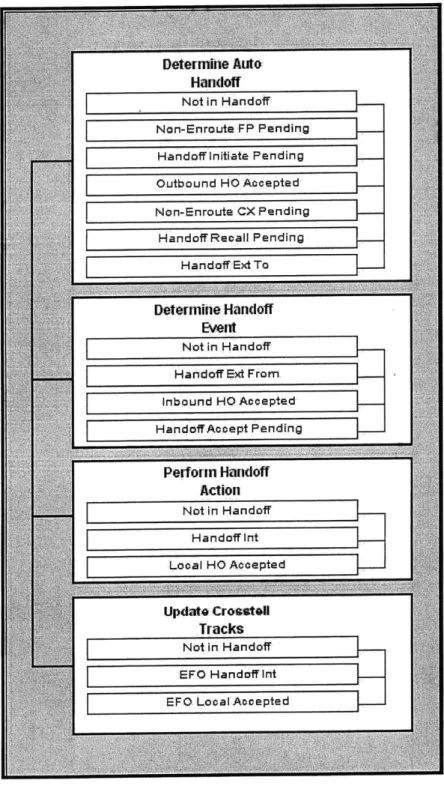
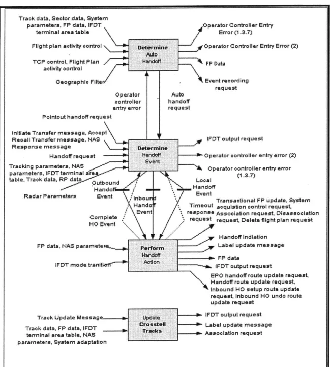
There are two types of Sector Handoff: Interfacility Handoff, and External Facility Owned (EFO) Handoff. The Sector Handoff component has four main modes:
1. Determine Handoff Event 2. Perform Handoff Action 3. Update Crosstell Tracks 4. Determine Auto Handoff
Determine HandoffEvent is responsible for interpreting:
* Handoff requests from the SDDs
" Handoff messages originating from automatic handoff processing
" Interfacility handoff messages originating from an ARTCC or TRACON (ARTS or STARS) facility (forwarded by the Manage IFDT messages function).
Perform HandoffAction processes requirements for each of a set of handoff actions.
Actions are defined for Events (generated by the Determine Handoff Events Function) and Handoff States as shown in Figures 2 and 3. Actions also appear in the Control Specification. Handoff actions are broken into three groups:
" Outbound HandoffActions - these are involved in handoff to other facilities, including recall of a handoff previously initiated by the local facility.
* Inbound HandoffActions - There are involved in handoff from other facilities, including recall of a handoff previously initiated by the remote facility.
* Local Handoff Actions - There involve no interfacility dialog for any transition.
Update Crosstell Tracks describes the requirements for the interfacility track updating
mechanism using the transmission of Track Update (TU) messages between TRACON and ARTCC Facilities for aircraft in Handoff.
also to provide an indication of when automatic interfacility handoff will occur. Adaptation data and TCP input defines when and if initiation of automatic handoffs should be performed.
Logic
Sector Handoff Logic General Principles
[2.1] The RDPS software will coordinate all handoff requests. (T G1 ) [2.1.1] All requests are from the SDDs, ARTCC or adjacent TRACON facilities, and automatic handoff initiation processing. (T Level 1: Introduction) [2.1.2] Output may be sent to the SDDs, ARTCC, or TRACON facilities (via the terminal area's host ARTCC).
(T
Level 1: Introduction)SDDS
[2.1.3.1] The responses to the SDD actions will be sent to the SDDs to acknowledge the action and report any error conditions that may occur.
(I
HL.R9, HL.C4, HL.C9)[2.1.3.2] Label Update Messages will be sent to the SDDs to update Pseudo-Track FDBs. (T HL.R9, HL.R12, HL.R15, HL.C3)
[2.1.3.3] Updates to Flight Data in the RDPS will result in the SDD copy of that data being updated. (t HL.R15, HL.C3)
[2.1.4] Message interchange with adjacent facility (T HL.C3)
[2.1.4.1] Handoffs between this STARS and an adjacent TRACON facility, all related messages are exchanged via the terminal area's host ARTCC.
(T
Level 1: Introduction, HL.C3)[2.1.4.2] If the source or ultimate destination is an adjacent TRACON, messages will be relayed by the ARTCC. (T Level 1: Introduction, HL.C3)
[2.1.4.3] In the remainder of the Process Handoffs section, the ultimate source or destination will be referenced rather than the facility to which the message is intermediately transmitted. (T HL.R2, HL.C3)
[2.1.4.4] Communication with an ARTCC or another TRACON is done via the Manage IFDT Messages Function by sending IFDT Output requests and receiving NAS Handoff Messages. (T HL.C3)
Determine Handoff Event Logic
[2.2] The interpretation process for this module involves validating messages against current RDPS Flight and Track data and adaptation data, and if the message is valid,
determining the event that has occurred or has been implied. (1 3.2) [2.2.1] Events can either be interpretive (in the case of most controller inputs) or explicit (as in the case of most interfacility messages). (T Level 1: Introduction) [2.2.2] Events are used along with the State Transition Diagram to derive required Actions.
(4
Figure 3) These Actions are specified in the Perform Handoff Action function:" Handoff Receiver Determination * Event Determination
" Handoff Request from the SDD * NAS Handoff Messages
* Transmission of NAS messages " Automatic Handoff Processing " Handoff Completion Timer " IFDT Mode Transition * Validation
" Standby Processing Differences
Handoff Receiver Determination
[2.2.3] The handoff receiver will be derived from the field in the input message or from the Flight Plan as follows: (1 3.2, Figure 3)
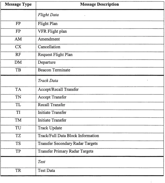
![Table 3: [3.1] System Messages](https://thumb-eu.123doks.com/thumbv2/123doknet/14675012.557739/87.918.105.775.115.291/table-system-messages.webp)
![Table 12: [3.1.9] Initiate NAS FP handoff to adjacent Tracon](https://thumb-eu.123doks.com/thumbv2/123doknet/14675012.557739/90.918.130.813.114.644/table-initiate-nas-fp-handoff-adjacent-tracon.webp)