Design of a Novel Centrifugal Casting Technique for the
Fabrication of Metal Matrix Composites
by
Hoe Phong Tham
B.S., Mechanical Engineering (2001)
University of Illinois at Urbana-Champaign
Submitted to the Department of Mechanical Engineering
in partial fulfillment of the requirements for the degree of
Master of Science in Mechanical Engineering
at the
MASSACHUSETTS INSTITUTE OF TECHNOLOGY
February 2003
MASSACHUSETTS INSTITUTE OF TECHNOLOGY
JUL 0 8 2003
LIBRARIES
@
2003 Hoe Phong Tham. All rights reserved.
The author hereby grants to Massachusetts Institute of Technology permission to
reproduce and
to distribute copies of this thesis document in whole or in part.
Signature of Author ...
Certified by
...
Toyota Professor
Certified by ...
Accepted by...
...
.
... ...
Department of Mechanical Engineering
17 January 2003
...
...
Merton C. Flemings
Emeritus, Department of Materials Science and Engineering
Director, Lemelson-MIT Program
Thesis Supervisor
...
David E. Hardt
Professor of Mechanical Engineering
Thesis Supervisor
...
Ain A. Sonin
Chairman, Department Committee on Graduate Students
Design of a Novel Centrifugal Casting Technique for the Fabrication of
Metal Matrix Composites
by
Hoe Phong Tham
Submitted to the Department of Mechanical Engineering on 17 January 2003, in partial fulfillment of the
requirements for the degree of
Master of Science in Mechanical Engineering
Abstract
Centrifugal casting has been used for hundreds of years to produce castings using centrifugal force to aid in filling the mold. In recent years, this process has been employed to produce metal-matrix composites, a new class of material that offers improved mechanical properties for high temperature applications and significant mass reduction compared to conventional metal alloys. However, despite its immense potential, this technique has not been further developed.
This thesis explores the design of a new system that aims to improve the centrifugal casting method for the infiltration of molten metal into ceramic preforms, by taking better advantage of the presence of the fluid pressure at the preform entrance to increase the infiltration pressure. It was shown that this technique provides a fluid pressure at the mold entrance that is far greater than that which can be attained by pouring alone, or by conventional centrifugal casting, in which the metallostatic "head" is limited by the relatively small length of metal in the radial direction. Samples of tin and aluminum composites reinforced by alumina powders of 1 and 9.5 microns in diameter, respectively, were produced, and the microstructures of the composites show that the technique has great potential for commercial application. The infiltration pressure achieved in producing the tin-alumina composite was estimated to be 37 atmospheres and that for the aluminum-alumina composite was 7 atmospheres, although calculations show that it could go beyond 12 atmospheres with the 2 hp centrifuge machine used in the laboratory.
Further analysis of the centrifuge system reveals that a much large infiltration pressure of
1000 atmospheres is achievable with a larger centrifuge motor and a new centrifuge design. The
motor horsepower requirement depends on the length of the runner, the speed of rotation and the time it takes for the centrifuge to accelerate to the desired speed. The "weakest link" in the design, it was found, was the runner of the centrifuge system, which must withstand the high pressures at the high operating temperatures of the centrifugal process.
Thesis Supervisor: Merton C. Flemings
Title: Toyota Professor Emeritus, Department of Materials Science and Engineering Director, Lemelson-MIT Program
Contents
1 Introduction 11
1.1 Centrifugal Casting . . . . 11
1.2 Fabrication of Metal-Matrix Composites . . . . 12
1.2.1 Squeeze Casting . . . . 13
1.2.2 Gas Pressure Infiltration . . . . 14
1.2.3 Lorentz Force Infiltration . . . . 14
1.2.4 Reactive Infiltration . . . . 15
1.2.5 Pressureless Spontaneous Infiltration . . . . 15
1.2.6 Vacuum Infiltration . . . . 16
1.3 Use of Centrifugal Casting for Fabrication of MMCs . . . . 16
1.3.1 Infiltration of Preforms . . . . 17
2 Design of New Apparatus for Centrifugal Casting 21 2.1 T heory . . . 21
2.2 Proposed Design . . . . 22
2.2.1 Reservoir and Runner System . . . . 23
2.2.2 Heater System . . . . 24
2.2.3 Aluminum Casing . . . . 25
2.2.4 Assembly of System . . . . 29
3 Heat Transfer Measurements and Calculations 31 3.1 Steady-State Temperature Distribution in Reservoir . . . . 32
3.3 Modeling of Steady-State Heat Transfer Calculations by Finite Differences Using
M icrosoft Excel . . . . 37
3.3.1 Finite Difference Method to Calculate Heat Transfer . . . 37
3.3.2 Results of Modeling . . . 53
3.4 Cooling Curves . . . 68
4 IEC CRU-5000 Centrifuge 70 4.1 Balancing and Vibration . . . . 70
4.2 Critical and Maximum Speeds . . . . 73
4.3 Time Taken to Reach Maximum Speed . . . . 74
5 Samples Obtained 76 5.1 Tin-Alumina Sample . . . . 76
5.2 Aluminum-Alumina Sample . . . . 77
6 New Machine Design 81 6.1 Capabilities of Current Machine . . . . 81
6.2 Factors to be Considered in New Design . . . . 85
6.2.1 Length of Runner, I . . . 85
6.2.2 Speed of Rotation, Q . . . . 86
6.2.3 Time Required to Reach Desired Speed, t . . . . 86
6.3 Motor Horsepower Requirement as a Function of Infiltration Pressure for Current System . . . . 87
6.3.1 Changes in Runner Length, 1, with Time, t, Fixed . . . . 87
6.3.2 Changes in Speed of Rotation, Q, with Time, t, Fixed . . . . 91
6.3.3 Changes in Values of t . . . . 91
6.4 New Runner Design for Achieving Infiltration Pressures of 100 MPa . . . . 95
6.4.1 Limitations of AISI 316 Stainless Steel Runner . . . . 95
6.4.2 New Runner Design Considerations . . . . 96
6.4.3 Motor Horsepower Requirement as a Function of Runner Length and Speed of Rotation for New Centrifuge System . . . 101
6.4.4 Conclusions Drawn from Present Analysis . . . 105
7 Conclusions 109
8 Recommendations for Future Work 111
List of Figures
2-1 A runner containing molten metal and a ceramic preform rotating about a vertical
ax is . . . . 22
2-2 Fully assembled reservoir and runner system . . . 24
2-3 Reservoir and runner system with heaters attached . . . . 25
2-4 Schematic of vertical portion of the aluminum casing . . . 26
2-5 Schematic of upper half of the horizontal portion of the aluminum casing . . . 27
2-6 Schematic of lower half of the horizontal portion of the aluminum casing . . . . . 28
2-7 Schematic of fully assembled aluminum casing . . . . 28
2-8 An exploded view of the assembly . . . . 29
2-9 A completely assembled system . . . . 30
3-1 Temperature distribution along the length of the reservoir . . . . 32
3-2 Steady-state temperature distribution in the different materials at the reservoir region . . . . 33
3-3 Heat fluxes out of different types of surfaces, given the same amount of heat energy in the system . . . . 34
3-4 Temperature distribution along the runner at steady state . . . . 35
3-5 An example of a nodal mesh . . . . 38
3-6 Nodal mesh set up in Microsoft@ Excel . . . . 40
3-7 Nodal mesh set up in Microsoft® Excel (with labels - dotted lines represent physical boundaries) . . . . 41
3-10 A typical centerline element . . . . 46
3-11 A cell "o" at the boundary of two different materials . . . . 47
3-12 A cell "o" at the boundary of two different materials, across different Ar and Az values . . . . 52
3-13 Approximate positions of the thermocouples in the runner system . . . . 55
3-14 A comparison of measured and calculated temperature distribution along the runner at steady state (for air at >700'C inside the runners) . . . . 56
3-15 A comparison of measured and calculated temperature distribution along the runner at steady state (for air at 300'C inside the runners) . . . . 58
3-16 A comparison of measured and calculated temperature distribution along the runner at steady state (for molten Al-4.5%Cu alloy inside the runners) . . . . 60
3-17 Calculated (expected) optimum temperature distribution along the runner at steady state . . . . 62
3-18 Calculated (expected) temperature distribution along the runner at steady state, with runner diameter and heater inner diameter doubled . . . . 63
3-19 Temperature distribution in the ceramic preform with the runner diameter and heater inner diameter doubled, compared with that of original setup . . . . 64
3-20 Calculated (expected) temperature distributions along the runner with different Fiberfrax@ thicknesses . . . 65
3-21 Calculated (expected) temperature distribution along the ceramic runner filled with molten iron at steady state . . . . 67
3-22 Cooling curves for different locations along the runner . . . . 68
4-1 The IEC CRU-5000 Centrifuge . . . 71
4-2 Exploded view of rotor-adaptor-casing assembly for the centrifuge . . . . 72
4-3 Speed of rotation of the centrifuge system as a function of time . . . . 74
5-1 Microstructure of aluminum oxide reinforced Sn-15%Pb composite . . . . 77
5-2 Microstructure of aluminum oxide reinforced Al-4.5%Cu composite . . . . 79
6-2 Load Torque as a function of speed for different systems with different moments of inertia . . . 89 6-3 Estimated motor horsepower requirement as a function of infiltration pressure,
which varies as a result of changes in the runner length (with time t fixed) . . . 90 6-4 Estimated motor horsepower requirement as a function of infiltration pressure,
which varies as a result of changes in the speed of rotation (with time t fixed) . . 92 6-5 Estimated motor horsepower requirement as a function of infiltration pressure,
which varies as a result of changes in the runner length (with different values of t) 93 6-6 Estimated motor horsepower requirement as a function of infiltration pressure,
which varies as a result of changes in the speed of rotation (with different values
of t) ... ... 94
6-7 Estimated motor horsepower requirement as a function of the runner length, at different values of t (small runner and preform) . . . 103 6-8 Estimated motor horsepower requirement as a function of the speed of rotation,
at different values of t (small runner and preform) . . . 104 6-9 Estimated motor horsepower requirement as a function of the runner length, at
different values of t (large runner and preform) . . . 106 6-10 Estimated motor horsepower requirement as a function of the speed of rotation,
List of Tables
3.1 Thermal conductivities of the materials used in the Excel model . . . 49 3.2 Emissivities of the materials used in the Excel model . . . . 50 3.3 Comparison of calculated results with measured results (for air at > 700 C inside
the runners)... ... 54
3.4 Comparison of calculated results with measured results (for air at 300'C inside
the runners)... ... 57
3.5 Comparison of calculated results with measured results (for molten Al-4.5%Cu alloy inside the runners) . . . 60 4.1 Critical and maximum speeds for parts of the centrifuge system (C.S. denotes
critical speed) . . . . 73
Acknowledgements
I would like to express my sincere gratitude to my thesis advisor, Professor Merton C. Flemings, for his insightful guidance, invaluable advice, cheerful support and patience towards me throughout the course of my research. My thanks also go out to my reader, Professor David E. Hardt, for his suggestions and advice, and to Professor Harold D. Brody for his insight on some of the problems I encountered.
I am grateful to Professor James L. Kirtley for taking time to explain the workings of a motor to me. Special thanks are also due to Professor Ty A. Newell from the University of Illinois at Urbana-Champaign, who taught me the very useful skill of modeling heat transfer using Microsoft Excel during my undergraduate years.
Further appreciation is extended to the Solidification Research Group, namely Jessada Wan-nasin, for his friendly guidance and help in designing and developing the centrifuge system, as well as for the many stimulating discussions that we had on this research; and Andy Martinez, for his generous assistance, unfailing support and friendship.
I am deeply indebted to my parents, who have always believed in me; and to my girlfriend Manquan Wong, for her love and support. I would also like to say a heartfelt "thank you" to my buddy, Roger Loh, a true brother who saw me through thick and thin. And to my other special friends, particularly Janice Tan, for the friendship and memories that I will always cherish.
And, last, but certainly not least, I thank the Lord for all His blessings, including the opportunity to come to the U.S. to further my studies in this prestigious university.
Chapter 1
Introduction
1.1
Centrifugal Casting
Centrifugal casting is defined as "the process of filling molds by (1) pouring metal into a sand or permanent mold that is revolving about either its horizontal or its vertical axis, or (2) pouring metal into a mold that is subsequently revolved before solidification of the metal is complete" [1]. The centrifugal casting process can be broadly divided into two types: horizontal centrifugal casting and vertical centrifugal casting.
The horizontal centrifugal casting technique uses the centrifugal force generated by a ro-tating cylindrical mold to throw the molten metal against the mold wall and form the desired shape [1]. The first patent on a centrifugal casting process was obtained in England in 1809, and the first industrial use of the process was in 1848 in Baltimore, when centrifugal casting was used to produce cast iron pipes [1]. Today, a great number of other hollow components including pipes, cylinder sleeves, piston rings and various hollow billets are produced using this method [2]. The biggest advantage in centrifugal casting is that the participation of centrifugal forces facilitates the casting of such hollow components without the use of central cores. This also allows the wall thickness to be controlled simply by controlling the weight of metal poured
[3].
Vertical centrifugal casting, as the name implies, is the type of centrifugal casting that rotates about a vertical axis. As with horizontal centrifugal casting, the vertical method can also be used to make pipes and cylinder sleeves as well. However, when fully up to speed, the
liquid in the mold takes up a parabolic shape, with the result that the wall at the base of the cylinder is thicker than that at the top [3]. Extra machining is therefore required to produce a parallel bore.
In addition to producing hollow cylinders described above (whereby such method is known as true centrifugal casting [1]), the range of applications of vertical centrifugal casting machines is considerably wider. Castings that are not cylindrical, or even symmetrical, can be made using this technique. In this method, molten metal is poured into a rotating mold. The centrifugal force of the rotating mold forces the molten metal against the interior cavity of the mold under constant pressure until the molten metal is solidified. This method is known as semicentrifugal
casting [1].
In recent years, both horizontal and vertical centrifugal casting methods have been employed to produce metal-matrix composites, a new class of material that offers improved mechanical properties for high temperature applications and significant mass reduction compared to con-ventional metal alloys.
1.2
Fabrication of Metal-Matrix Composites
Metal-matrix composites (MMCs) are defined as "engineered combinations of two or more materials (one of which is a metal) in which tailored properties are achieved by systematic combinations of different constituents" [1]. Conventional monolithic materials have limitations in terms of achievable combinations of properties, such as strength, stiffness, coefficient of thermal expansion, etc. By combining these materials with continuous or discontinuous fibers, whiskers or particles - usually of a ceramic material - of different sizes and in different volume fractions, the properties of the new material that is produced from this combination may be improved considerably, and these properties can be significantly different from the properties of the constituents [4].
The fabrication techniques in processing MMCs are many. A basic requirement is the initial intimate contact and the intimate bonding between the ceramic phase and the molten alloy [1]. However, because of the poor wettability of most ceramics by molten metals, intimate contact between ceramic and metal frequently needs to be promoted by artificial means, and these can
be broadly divided into two categories: solid state and liquid state fabrication techniques [5]. Solid-state processes are generally used to obtain the highest mechanical properties in MMCs [5], and these include powder metallurgy [6], diffusion bonding [7] and high-rate consolidation
[8].
However, a majority of the commercially viable applications of MMCs are now produced by liquid-state processing because of the inherent advantages of this processing technique over the solid-state techniques mentioned above. For example, liquid metal is generally less expensive and easier to handle than are powders, and the composite material can be produced in a wide variety of shapes, using methods already developed in the casting industry for unreinforced metals [5]. There are four broad classes of liquid-phase techniques: preform infiltration, mixing, spray co-deposition and in-situ fabrication [41.
The use of centrifugal casting in the fabrication of MMCs is one of the infiltration processes of the liquid phase method. The other infiltration techniques include: squeeze casting, gas pressure infiltration, Lorentz force infiltration, reactive infiltration, pressureless spontaneous infiltration, and vacuum infiltration [4, 5]. A major advantage of infiltration processes is that they allow for near-net shape production of parts fully or selectively reinforced with a variety of materials. If cold dies and reinforcements are used, or if high pressures are maintained during solidification, matrix-reinforcement chemical reactions can be minimized, and attractive, defect-free matrix microstructures can be achieved [5]. However, the limitations of these processes are the need for the reinforcement to be self-supporting, either as a bound preform or as a dense pack of particles or fibers, and that heterogeneity of the final product may result from preform deformation during infiltration or from clustering of fibers that are detrimental to the composite mechanical properties. Also, tooling may be expensive if high pressures are used [5). The following sections provide a brief overview of the different infiltration processes mentioned.
1.2.1 Squeeze Casting
A strategy to overcome poor wetting between a ceramic and a metal is to supply mechanical work to force the metal into a preform that it does not wet. Although the purpose of an externally applied pressure is to overcome the capillary forces, higher pressures can provide additional benefits such as increased processing speed, control over chemical reactions, refined
matrix microstructures and better soundness of the product through feeding of solidification shrinkage [5].
Pressure, in this case, may be applied mechanically, which involves a force that is exerted on the molten metal by the piston of a hydraulic press, and subsequently maintained during solidification. The pressures involved usually range from about 10 to 100 MPa. This type of infiltration process is currently the most widely investigated for commercial applications, and has been directly adapted from established processes designed to cast unreinforced metals
[9, 10, 11, 12, 13, 14, 15].
Composites produced by this method generally feature a pore-free matrix. They also show uniform reinforcement distribution, reduced fiber-to-fiber contact, and solidification of eutectic at reinforcement surface [4]. However, application of pressure may induce preform deformation or breakage during infiltration [10, 15, 16, 17, 18, 19, 20].
1.2.2 Gas Pressure Infiltration
The pressure required to force metal into the preform of reinforcing phase may also be applied by an inert gas, such as Argon, typically pressurized in the 1 - 10 MPa range [21, 22, 23, 24, 25, 26, 27]. Although the use of higher pressures (up to 17 MPa) has been investigated for aluminum matrix composites [28], the safety issues involved become a major limiting factor. With gas pressure infiltration, however, relatively inexpensive tooling (compared to squeeze casting) is usually sufficient, and a better control of atmosphere is possible [4].
1.2.3 Lorentz Force Infiltration
The use of electromagnetic body forces to drive molten metal into a preform was developed by Andrews and Mortensen [29], where they fabricated alumina fiber-reinforced aluminum composites using this method. In the Lorentz force-driven infiltration, the metal is subjected to a strong and transient high frequency electromagnetic (EM) field which interacts with the eddy currents produced within the metal [29]. This interaction results in a Lorentz body force on the metal which drives the metal into the preform when the preform is suitably oriented with respect to the direction of the force.
castings. However, the frequency required for infiltration is very high, and even then, only a maximum fiber volume fraction of 25% has been achieved, and there is a limit to the infiltration length that can be attained using this method [4].
1.2.4 Reactive Infiltration
Reactive infiltration is essentially an in-situ composite fabrication process in which a compound is formed by simultaneous infiltration and reaction of a porous solid by a melt, such as the infiltration of silicon in porous carbon, and the infiltration of aluminum in titanium oxide, mullite and nickel-coated aluminum oxide [4].
Complex, near net shape components with little overall change in the part dimensions can be produced by this technique, and the infiltration conditions can be controlled to achieve the desired level of reaction and structure [4]. Unfortunately, the reaction is usually exothermic and may initiate explosively. In addition, the requirement of a reaction during infiltration clearly limits the choice of reinforcement-matrix combinations to those systems where a sufficiently large driving force exists for chemical interaction at the processing temperatures. Also, the reaction kinetics need to proceed with sufficient rapidity to form an appreciable quantity of the product phase during the time period of infiltration [4].
1.2.5 Pressureless Spontaneous Infiltration
Spontaneous infiltration of preforms by metals in the absence of an external pressure can be effected if the melt and preform compositions, temperatures and gas atmosphere are controlled such that good wetting conditions are achieved for self-permeation (wicking) of the metal in the preform [30, 31, 32, 33, 34]. Examples of such composites produced include titanium-carbide-reinforced steel and nickel-base alloys [35]. Another example is the PRIMEXTM pressure-less infiltration process, developed by Lanxide Corporation, Newark, Delaware [36], whereby aluminum-magnesium alloys infiltrate ceramic preforms at temperatures between 750'C and 1050'C in a nitrogen-rich atmosphere.
As with reactive infiltration, the spontaneous infiltration technique has the ability to fabri-cate void-free net-shape metal- and ceramic matrix composites having high integrity. However, the shortcomings of this process are high capital cost of processing equipment, stringent control
on atmosphere and temperature, restrictions on matrix chemistry (e.g. in the case of aluminum alloys, magnesium is required), and excessive reaction of the matrix with the reinforcement due to extremely long contact times (typically 1 to 10 hours) [4]. In the PRIMEXTM pressureless infiltration process, for example, infiltrate rates can only reach a maximum of 25 cm/hour [36].
1.2.6 Vacuum Infiltration
For some matrix-reinforcement systems, creating a vacuum around the reinforcement provides a sufficiently large negative pressure differential between the preform and the surroundings, which, in countergravitational configuration, drives the liquid metal through preform interstices against the forces of surface tension, gravity and viscous drag [37].
The process is relatively simple and does not require extensive tooling [4]. Furthermore, it also produces MMCs that have less porosity and oxidation than low-pressure techniques. However, a maximum pressure of 1 atm only can be created for impregnating the fibers; this magnitude of pressure may not be adequate for melt ingress in densely packed preforms of non-wetting fibers. Therefore, vacuum infiltration is usually done in conjunction with chemi-cal methods of wettability enhancement (e.g. fiber surface modification, addition of wetting-enhancing elements to the matrix alloy, etc.) [4].
1.3
Use of Centrifugal Casting for Fabrication of MMCs
In addition to the numerous infiltration techniques described above, centrifugal casting methods have also been used for the fabrication of MMCs, such as the production of tubular reinforced metal [38, 39, 40, 41, 42, 43, 44], using the horizontal centrifugal casting method. Subjecting metallic slurries containing ceramic reinforcement to the action of a centrifugal force - created by rotation of the mold containing the slurry - results in the formation of two distinct zones within the slurry: a particle-enriched zone and a particle depleted zone. Different densities of the particles and melt cause spatial segregation under the action of the centrifugal force in a manner similar to the segregation observed in sand castings under the influence of gravitational force [4]. If the particles are lighter than the melt (e.g. graphite or mica in aluminum or tin
centrifugal castings [4], resulting in the formation of antifriction surfaces for bearing applications [1]. Similarly, particles heavier than the melt (e.g. zircon, silicon carbide or aluminum oxide in aluminum alloys) will segregate near the outer periphery of the casting, leaving behind a predominantly metal-rich zone which provides a tough backing material, and resulting in the formation of hard, abrasion resistant surfaces near the outer periphery.
In addition to making hollow components that consist of two distinct zones by the horizontal centrifugal casting method, the specific gravity difference between particles and melts can also be taken advantage of, through the vertical centrifugal casting method, to make solid objects that either show a "coating" of reinforced material near the casting surface, or a gradient in the amount of reinforced material within the object [45, 46, 47].
Sugishita et al. [45] produced aluminum and tin based composites containing hollow carbon microballoons obtained from volcanic ash. The microballoons were packed in an alumina tube which also served as a crucible for molten metal atop the powder bed. The infiltration and dispersion of powders was carried out at high rotational speeds of 2680 to 4000 RPM, and the rotation was continued until the solidification was completed. The carbon microballoons were concentrated near the casting surface. During rotation, the centrifugal force pressurizes the molten metal into the interstices of the particulate bed. Also, the particles, being lighter than the metal, rise up towards the axis of rotation along the crucible walls where the shear forces in the melt compress them against the walls. As the rotation is continued through solidification phase, the particles are "frozen in" at their final position in the casting [4].
From this idea, the vertical centrifugal casting method can be brought a step further by infiltrating entire ceramic preforms to fabricate fiber-reinforced metal composites, so that the reinforced material in the composite produced is uniformly distributed. Large rotational ve-locities can generate a centrifugal force big enough to overcome the capillary forces for melt penetration and viscous forces for metal flow in the preform [4].
1.3.1 Infiltration of Preforms
The infiltration of a ceramic preform by a molten pure metal or alloy was first attempted by Noordegraaf et al. [48]. In this process, a shaped object is cast by subjecting a mold to a centrifugal acceleration directed to the bottom of the mold. A dispersed filler (particles of a
ceramic material) is placed in the mold before adding the melt, so that upon centrifuging, the centrifugal force field that is set up will force the melt into the cavities between the particles. This process, the authors acknowledged, is a modification of that in Reference [45]. Its aim, however, is to make shaped objects in which the filler is dispersed as homogeneously as possible throughout the entire metal matrix, by preventing, as far as possible, the filler from moving
during the filling of the mold with pure metal or alloy.
For some reason, however, this invention was not further pursued and developed, and the centrifugal casting process for the fabrication of MMCs was not commercialized, even though all the other infiltration methods discussed in the previous sections have already been adopted commercially. Furthermore, few papers have been published on the infiltration of molten metal into ceramic preforms by centrifugal force [49, 50, 51, 52]. Most of the articles related with centrifugal force are concerned with the segregation of particles in molten metal during solidi-fication [50].
Jiang et al. fabricated an alumina short fiber reinforced aluminum alloy via centrifugal force infiltration [49]. Their technique was similar to the vertical centrifugal casting method of producing hollow cylinders, whereby they placed an aluminum oxide preform in a cylindrical stainless steel mold vertically fixed to the end of the driveshaft of a motor. The molten metal was poured into the mold that was rotating at high speeds (1000 - 6000 RPM), and the metal penetrated the preform and solidified under centrifugal force. A cylindrical MMC was thus obtained.
The authors found that the hardness and wear resistance of the MMCs prepared via the centrifugal force infiltration route are almost identical to those of composites obtained via squeeze casting, and that the molten infiltration process was markedly affected by the pouring temperature, preheated mold temperature, and the time of application of centrifugal force.
Nishida et al. also investigated the infiltration of fibrous preform by molten aluminum in a centrifugal force field [50]. In their experiment, they rotated a preheated graphite container of uniform cross-section placed horizontally from a vertical axis of rotation, in which a preheated fibrous preform was placed at the end. When the rotation speed reached a desired value, they poured molten pure aluminum into a pouring device that was concentric with the rotation shaft.
in the molten aluminum due to centrifugal force when the container was instantaneously filled, and infiltration of aluminum into the preform was thus initiated.
The authors found that if the pressure generated by centrifugal force exceeds the threshold pressure due to lack of wettability, infiltration progresses to the bottom of the graphite container. This was confirmed by comparing the results obtained with calculated values.
Nishida et al. later wrote a second paper [51] that models the infiltration of molten metal in a fibrous preform by centrifugal force. The authors recognized that it is difficult to obtain the appropriate infiltration conditions only by experimental work alone, and thus they developed a theoretical analysis to aid in understanding the infiltration process. Unfortunately, however, the process was not developed further, even though the authors recognized the potential of this infiltration technique.
Taha et al. [52] compared the two types of MMCs fabricated by centrifugal casting and by squeeze casting, and discussed their infiltration mechanisms. They also briefly presented the main structural features obtained in the composites prepared.
The authors found that the pressure needed for full infiltration is less in centrifugal casting than in squeeze casting. In centrifugal casting, a pressure of 120 kPa was sufficient to achieve full infiltration of the specimen for aluminum oxide powder of 47 pttm in diameter. The lowest squeeze casting pressure used to achieve full infiltration of the specimen, even for a much coarser aluminum oxide grain size of 115 pam, was of the order of 65 MPa - more than 500 times the pressure needed in centrifugal casting to infiltrate a much finer powder size. This same conclusion of a lower infiltration pressure needed in centrifugal casting than in squeeze casting was reached by Walter [53] many years earlier.
The authors also discovered that full infiltration in centrifugal casting is achieved in less than 2 seconds, although more than half a minute is necessary for full densification of the specimens. In squeeze casting, however, full infiltration is achieved in 25 seconds. This is a much longer time in comparison with the few seconds required in centrifugal casting. The authors hypothesized that this might be due to the dynamic action of the centrifugal force which could shorten the infiltration time. The long infiltration time in squeeze casting was confirmed in an earlier work by Asthana et al. [54], in which the infiltration took 3 to 30 minutes.
displace-ment occurred during infiltration, an almost uniform distribution of aluminum oxide particulates was achieved, observed in both longitudinal and transverse sections. The inter-particle spacing was found to have an almost constant value in the specimen. On the other hand, microscopic observations on squeeze-cast specimens indicate that although the distribution of aluminum ox-ide in the transverse section was almost uniform, it was not uniform in the longitudinal section. A gradual increase in the inter-particle spacing was observed from the bottom to the top of the specimen [55]. Generally, the inter-particle spacing obtained in squeeze casting was relatively larger than that in centrifugal casting.
These observations all point towards the enormous potential that centrifugal casting has in the fabrication of MMCs. This work is therefore a first attempt to study the possibilities that exist in such a technique. A new centrifuge system will be designed and built, as well as studied and discussed, with samples of MMCs obtained to test the system's capabilities. The limitations of this design will then be analyzed, and with the knowledge obtained from this analysis, a second improved design will be proposed.
Chapter 2
Design of New Apparatus for
Centrifugal Casting
2.1
Theory
As pointed out in the previous chapter, the potential of using centrifugal casting in the fabri-cation of metal-matrix composites is immense. In the centrifugal casting techniques used by Nishida et al. [50] and Taha et al. [52], it is noted that both have failed to take advantage of the presence of the fluid pressure (or metal head) at the preform entrance to increase the infiltration pressure of the molten metal into the ceramic reinforcement.
From Reference [50], it is known that the fluid pressure, P, acting on the preform surface is given by:
P
=" r- ro (2.1)2
where Pm is the density of the molten metal, w the angular velocity (= 27rN, where N is
revolutions per second), and r1 and ro denote the radii of revolution of the preform inner
surface and of the molten metal column surface respectively [50], as illustrated in Figure 2-1: In the experiment conducted by Nishida et al. [50], due to the centrifugal force field set up in the container, the stream of molten metal flowing into it through the pouring device is broken up, because the speed of pouring can never match the speed with which the molten
Metal
(4)
ri 5Ceramic Preform
Center of Rotation
Figure 2-1: A runner containing molten metal and a ceramic preform rotating about a vertical axis
metal travels through the container to the preform. This results in the molten metal filling the container in jets that leads to very a small value of
(r
- rd). The low and uncontrolled radial depth of the fluid gives rise to a low fluid pressure. This same drawback is observed in the paper by Taha et al. [52], in which the length of molten metal in the steel tube is very short,thus setting ro at a large and finite value. Furthermore, it is clear that as infiltration of the molten metal into the preform occurs, ro increases, thus further decreasing the fluid pressure. As a result, infiltration might not be complete, if the fluid pressure drops below the threshold pressure during the infiltration process. The threshold pressure, Pth, is the pressure that is required to infiltrate the preform (which exists due to the lack of wettability), and is given by
[56]:
4VfycosO
6V ycos(
Ph
dh
o P,d(2-2)
d (1-V, d, 1- V,P
where Vf (Vp) is the fiber (powder) volume fraction, y the surface energy of the molten metal, 0 the contact angle, and df (dp) the diameter of the fiber (powder).
2.2
Proposed Design
importance of the extended length of the molten metal in the runner is that, upon centrifuging, it provides a metal head at the preform entrance that is far greater than that which can be achieved by pouring alone. By extending the fluid length in the runner into the center of rotation by means of a reservoir filled with molten metal, ro is essentially reduced to zero. From Equation 2.1, it is clear then that the infiltration pressure will be a maximum at any given rotation for any given metal.
The ability to achieve very high pressures is important in the infiltration of preforms with high threshold pressures, i.e. in the making of metal matrix composites (MMCs) that have high fiber/powder volume fractions, large contact angles, or small fiber diameters (or sub-micron ceramic powders). Such high pressures can also help in infiltrating the preform sufficiently rapidly so that little or no solidification takes place before the preform is completely infiltrated (which is especially crucial in the infiltration of cold preforms), as well as in the removal of undesirable pores in the MMCs - the presence of which can significantly reduce the mechanical properties of the material, such as its fracture strength. In addition, the high pressures achieved can also be used in microcasting, where molten metal is made to flow through microchannels in order to cast micro-parts for microelectromechanical systems (MEMS) applications.
An additional advantage of having a reservoir of molten metal at the center of rotation connected to a long runner - that is also completely filled with molten metal - is that the metal remains as a continuous body during filling, so that the metal head infiltrating the ceramic preform will be constant and controlled, as well as steady and laminar. This not only ensures that the preform will be fully infiltrated, but may also result in a better and more homogenous microstructure for the MMC produced.
2.2.1 Reservoir and Runner System
The reservoir and runner system is made up of three Swagelok@ AISI 316 stainless steel tubings (part number SS-T8-S-065-20) [57] - one for the reservoir and two for the runners. These tubings have a nominal outer diameter of 1.27 cm (0.5") and a nominal wall thickness of 0.1651 cm (0.065"), thus giving a nominal inner diameter of 0.9398 cm (0.37"). The tubing that is used for the reservoir is cut to a length of 11.7 cm (4.6") and the runners are each cut to a length of
Figure 2-2: Fully assembled reservoir and runner system
All three tubings are connected together by a Swagelok@ stainless steel union tee (part number SS-810-3) [57]. The end of each runner is capped using a Swagelok@ stainless steel cap (part number SS-810-C) [57], which holds the ceramic preform or powder.
In order to fit the reservoir snugly into the internal surface of a pair of semi-cylindrical heaters (which will be discussed in the following section), a cylindrical sleeve is machined out of a block of carbon steel, such that its inner diameter coincides with the outer diameter of the reservoir, and its outer diameter matches the inner diameter of the heaters. The reservoir is then inserted through the steel sleeve, and a Swagelok@ stainless steel male connector (part number SS-810-1-8) [57] is attached to the top end of the reservoir to keep the sleeve in place. The complete setup of the reservoir and runner system is shown in Figure 2-2. It has a total length of 44.45 cm (17.5") and a height of 19.05 cm (7.5").
2.2.2 Heater System
Three pairs of heaters are used - one for the reservoir and one for each of the two runners. These heaters are RH ceramic high temperature 1800 semi-cylindrical heaters from Thermcraft, Incorporated. Each heater is a resistance heater made from iron-chrome-aluminum wire helically wound and placed in a grooved ceramic refractory holder, and has the capability of being heated to a maximum temperature of 1204*C (2200'F) [58].
'N
6
-I-Figure 2-3: Reservoir and runner system with heaters attached
number RH212) [59] and those used for the runners are 20.32 cm (8") (model number RH214)
[59]. These heaters are placed around the reservoir and runners in such a way that they completely enclose them. Figure 2-3 shows the same reservoir and runner system in Figure 2-2, but now with the heaters attached.
2.2.3
Aluminum Casing
In order to perform centrifugal casting using the setup in Figure 2-3, a casing needs to be made which functions to not only hold the entire setup in place, but also to minimize the amount of heat loss into the surroundings. The problem of heat loss is especially important in this setup because the operating temperature in infiltrating molten aluminum into a ceramic preform is at least 645 C - the liquidus of the Al-4.5%Cu alloy used for the experiment [60].
For this purpose, an outer casing is machined out of a block of A356 aluminum alloy to house the entire reservoir, runner and heater system. This casing is made up of two sections, a vertical one for the reservoir and its heaters and a horizontal one for the runners and their corresponding heaters. This horizontal casing is further divided into two portions: an upper
'01 61 r 4.00 8.00 3.00 o 0 o 0
Figure 2-4: Schematic of vertical portion of the aluminum casing
half and a lower half.
Vertical Casing
The vertical portion of the aluminum casing that houses the reservoir and its pair of 4-inch heaters is simply a vertical rectangular tube 10.795 cm (4.25") in height, with flanges coming out at the bottom so that it could be attached to the top half of the horizontal casing below it. Figure 2-4 shows a schematic of this casing. This drawing, as well as all the drawings in Figures 2-5 - 2-9, is made using SolidWorks® 3D Modeling Software, distributed by SolidWorks
Corporation. All dimensions in the figure are in inches.
Horizontal Casing - Upper and Lower Halves
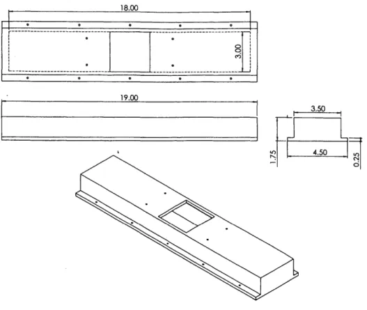
The two halves that make up the horizontal portion of the aluminum casing, which houses the runners and their corresponding pair of 8-inch heaters, are long rectangular channels that measure 48.26 cm (19") in length. The top half of the casing is 4.445 cm (1.75") in height while
1 0 0 a_ 0 0 90 3.50 LO) 4.50 6
Figure 2-5: Schematic of upper half of the horizontal portion of the aluminum casing
could be attached to each other. The upper half of the casing differs from the lower one in that it has a square hole at the center for the reservoir to pass through it. Also, the bottom half of the casing has "legs" factored into its design so that it could be attached to a custom-made adaptor that connects the whole aluminum casing to the rotor of the centrifuge. This extra pair of "legs" on the lower half of the casing accounts for its greater height compared to its upper counterpart. Figures 2-5 and 2-6 show a schematic of each of these two halves of the aluminum casing. Again, all dimensions in the figures are in inches.
The aluminum casing, when fully assembled, looks like that in Figure 2-7. The casing measures 48.26 cm (19") in length, 21.082 cm (8.3") in height and 11.43 cm (4.5") in width.
18.00
19.00 4.50
3.50
Figure 2-6: Schematic of lower half of the horizontal portion of the aluminum casing
Figure 2-8: An exploded view of the assembly
2.2.4 Assembly of System
Once the aluminum casing is constructed, the whole system is ready for final assembly, which consists of the aluminum casing, the reservoir and runner system, as well as the three pairs of heaters. Figure 2-8 shows the exploded view of the assembly, followed by Figure 2-9, which shows the entire assembled system. Once assembled, the whole setup rotates about a vertical axis through its center, which, because symmetry has been maintained throughout the design, is also the center of mass of the system.
Not shown in Figures 2-8 and 2-9, however, is the Fiberfrax@ insulating material (dis-tributed by Eastern Refractories Company, Inc) that is packed inside the aluminum casing to minimize heat loss from the system. This Fiberfrax© layer lies between the inner surface of the casing, and the reservoir, runners and heaters. Hence, the interior of the casing is lined with
Figure 2-9: A completely assembled system
Fiberfrax , forming a thick nest onto which the reservoir-runner-heater assembly is placed. This insulating layer of Fiberfrax@ has shown to be very effective in keeping the heat inside the system.
Chapter 3
Heat Transfer Measurements and
Calculations
The entire reservoir and runner system is assembled and surrounded by heaters as described in Chapter 2, and placed in a nest of Fiberfrax@ insulating material in the A356 aluminum casing, with k-type thermocouples placed at strategic locations to measure the temperature distribution of the system at high temperatures. An Omega@ OM-3001 Datalogger and a DT9806 data acquisition module from Data Translation, Inc. are used for this purpose.
The first experiment conducted is to heat the reservoir and runners to an internal temper-ature of 720'C, and then maintained at that tempertemper-ature at steady state, with only air inside the system. Temperature control of the system is achieved by controlling the amount of current flowing through the heaters, using two Omega@ CN76030 Temperature Controllers and one Omega@ CN8201-R1 Temperature Controller - one for each pair of heaters.
The following sections discuss the results of this experiment, as well as some calculations made to deduce the heat transfer coefficients. In addition, a simple heat transfer model is created in Microsoft@ Excel to calculated the temperature distribution in the runner system at steady state. In the last section of this chapter, we will look at transient heat loss in the runner system.
5-0
4_
0 Temperature Distribution
E 3 - - - -Set Temperature (7200C)
8
Outline
of reservoir-Outline
ofreservoir-0
M runner system runner system
-2
0
0 200 400 600 800 1000 1200 1400 Temperature (*C)
Figure 3-1: Temperature distribution along the length of the reservoir
3.1
Steady-State Temperature Distribution in Reservoir
Figure 3-1 shows the temperature distribution within the reservoir at steady state.
Except for the top part of the reservoir, which is exposed to ambient air above it, we see a relatively uniform temperature distribution along the bottom half, in the range 0" to 4". Therefore, assuming the case of an infinite cylinder in this region (and thus reducing this to a 1-D heat transfer problem), we can calculate the convection heat transfer coefficient, h,, on the outside surface of the aluminum casing. The radiation heat transfer coefficient, h,, is assumed to be negligible, given the relatively low temperature of the aluminum casing and surrounding air, as well as the low emissivity of the casing.
In 1-D, the heat flux out of the internal heating layer of the heater surface is equal to the heat flux into the Fiberfrax@ insulating material, and is given by:
Wall of stainless Fbrrx
steel tube (reservoir)Hetr Fbfax
Hetflux
Centerline
r =0.625" r= 1.03125" r = 1.5" T =7300C T =7130C T = 252*C
Figure 3-2: Steady-state temperature distribution in the different materials at the reservoir region
kT-T2
q
4
2 (3.1)r
L (r~
where k and r are thermal conductivity and radius, respectively, of the material under consid-eration, T, is the known temperature at the outer radius ri, and T2 is the known temperature
at the inner radius r2 [61].
The heater has inner and outer diameters of 1.25" and 2.0625" respectively [59]. Therefore, the Fiberfrax® insulating material also has a corresponding inner diameter of 2.065". Its outer diameter is taken to be 3", equal to the inner dimension of the aluminum casing at the reservoir region. The temperatures at these regions are obtained using thermocouples. Figure 3-2 illustrates the steady-state temperature distribution in the different materials.
Taking the thermal conductivities of the heater and Fiberfrax® to be 4.03 W/mK and 0.105 W/mK respectively (from Table 3.1 on page 49), it is found, from Equation 3.1, that the heat flux out of the heater, qh-out, is 5.22 kW/m 2. The heat flux into the Fiberfrax , qf-in,
is found to be 4.93 kW/m 2, which is in excellent agreement with qh-out calculated.
Smaller surface area; larger qout 3,, Larger surface area; smaller q0u, 3,"
Figure 3-3: Heat fluxes out of different types of in the system
surfaces, given the same amount of heat energy
is 3.39 kW/m2. Assuming that the aluminum casing is sufficiently thin such that its outside temperature is equal to its inside temperature - a reasonable assumption since aluminum has a very high thermal conductivity - we can set this temperature equal to the outside temperature of the Fiberfrax
However, the heat flux out of the aluminum casing, qal-out, cannot be set equal to qf-out because the actual outer surface area of the casing, being rectangular, is larger than that of a cylindrical surface assumed. This results in a smaller heat flux out of the aluminum casing. Figure 3-3 illustrates this.
A square with sides 3" in length has a perimeter that is roughly 1.27 times that of a circle with a diameter of 3". Therefore, the heat flux is correspondingly approximately 1.27 times less. Hence, we assume that qal-out is 2.67 kW/m2.
Assuming that h, is negligible, h, can be found from the basic heat transfer equation:
q=kh(T
-amnb) (3.2)Given that the ambient temperature, Tamb, is 19'C, we find that h, is therefore 11 W/m2K.
-0 r 1
700-600
-S500 - Reservoir
--0R r Measured Temperature
4 Aluina Column ... Predicted Terrperature
Set Terperature (72000) E 300- I- 200-Fiberf rax@ 100-0 0 2 4 6 8
Distance from Center of Reservoir (inch)
Figure 3-4: Temperature distribution along the runner at steady state
3.2
Steady-State Temperature Distribution in Runner System
The temperature distribution in the runner system is measured in a similar way using thermo-couples placed at strategic locations. Figure 3-4 shows the temperature distribution along the inside of the runner, as well as that inside the ceramic reinforcement (aluminum oxide) at the end of the runner, and outside the runner in the Fiberfrax region.
Figure 3-4 allows us to calculate the heat transfer coefficients in the air gap between the stainless steel runner and the interior of the heater. The predicted uniform temperature inside the runner is estimated to be 744.5'C, and this is assumed to be equal to the temperature of the stainless steel tube as well, since the internal diameter of the tube (0.37") is too small to justify a significant temperature difference between the tube wall and the air column within the tube.
The temperature of the heating layer of the heater surface facing the runner is measured to be 756.6*C at steady state. This gives an average air temperature, Tavg, of 750.55'C between
the heater and the runner. From Table B.4 of Reference [61], at 1000 K, air has a kinematic viscosity, v, of 121.9 x 10⁻⁶ m2/s, a thermal conductivity, k, of 66.7 x 10⁻³ W/mK, and Prandtl number, Pr, of 0.726. From these values, the Grashof number, Gr, can be found, using:
Gr
Grl
3 gIAT2 (3.3)in which 1 represents some characteristic length parameter and A T represents the temperature difference between the heater and runner surfaces [62]. g is the acceleration due to gravity and /3 is simply the reciprocal of Tavg, in K- 1. For free convection around horizontal cylinders, 1 is based on the cylinder diameter as the characteristic length [62], which, in this case, is the outer diameter of the stainless steel runner (0.0127 m, or 0.5").
The value of Gr calculated is 16, which gives a combined GrPr value of 11.6. Referring to Fig. 9.2 in Reference [62], the Nusselt number, Nu, is found to be 1.58. The convection heat transfer coefficient, he, is given by [61]:
k
h =Nu-- (3.4)
which gives us h, = 8 W/m 2K.
Due to the very high temperatures of both surfaces of the heater and the runner, which result in the stainless steel runner being highly oxidized - thus leading to a high emissivity of the runner - the radiation heat transfer coefficient is considered significant. However, this cannot be calculated straightforwardly because, unlike the value of he, which does not change much even though the temperature along the runner changes (as shown in Figure 3-4), hr changes significantly with different surface temperatures.
The method of calculating h, at different regions along the runner, corresponding to the different temperatures, shall be discussed in a later section.
3.3
Modeling of Steady-State Heat Transfer Calculations by
Finite Differences Using Microsoft
Excel
While obtaining accurate measurements of the temperature distributions in and around the reservoir and runners are important, this is only an isolated case given the particular design of the system. In general, we might be interested to know what the temperature distributions would be like if we were to change the design parameters or the operating parameters to conditions where no experimental measurements were possible. For example, this includes cases where the diameter of the runner is doubled, thus increasing by 4 times the volume of ceramic sample to be infiltrated; or where the thickness of the insulating layer of Fiberfrax® around the heater were changed; or where we have molten iron (instead of aluminum) in a ceramic runner. It might also be of interest to know what temperature we should heat the heaters to in order to achieve the temperature distributions desired in the runners. As it is impractical to conduct numerous experiments to find out the answer to each of the above questions, and the complexity of the design setup also precludes the use of analytical methods to predict temperature distributions, a simple heat transfer model of the runner system is therefore developed using a spreadsheet in Microsoft Excel to calculate the temperature distributions, by the method of finite differences.
3.3.1 Finite Difference Method to Calculate Heat Transfer
The use of finite differences to solve heat transfer problems is a fairly straightforward procedure for most situations, and this topic has been extensively covered by numerous authors who have written books on heat transfer [61, 62, 63, 64, 65, 66, 67). This section presents a brief discussion on the principles of using the finite difference method as applied to a spreadsheet in Microsoft Excel.
The basic principle of the numerical approach to a heat conduction problem is the re-placement of the differential equation for the continuous temperature distribution in a heat-conducting solid by a finite-difference equation which must be satisfied at only certain points in the solid [61]. An Excel spreadsheet, where each cell in the spreadsheet represents a "node", or point, in the system, is therefore an ideal tool for such calculations. The temperature at that
Interior cell
1W
-
-*
0
0 0
Outside corner cell (1/4 interior cell)
Side/top/bottom cell
r (1/2 interior cell)
L%
7~ Inside corner cell(3/4 interior cell)
Figure 3-5: An example of a nodal mesh
node is determined from the equations that relate it to its neighboring nodes [681.
Nodal Mesh
The first step in any numerical analysis is to select the points where the temperature shall be determined. A mesh is defined that covers the region where temperature predictions are of interest. This mesh consists of small regions of orthogonal geometry. Figure 3-5 shows an example of a mesh.
In Figure 3-5, a 2-D mesh displays interior nodes and three types of boundary cells. Tem-peratures are assumed to be located at the center of interior cells. In order to have temperature information directly on a boundary, boundary cells are either three-quarters, half, or one-quarter the size of interior cells.
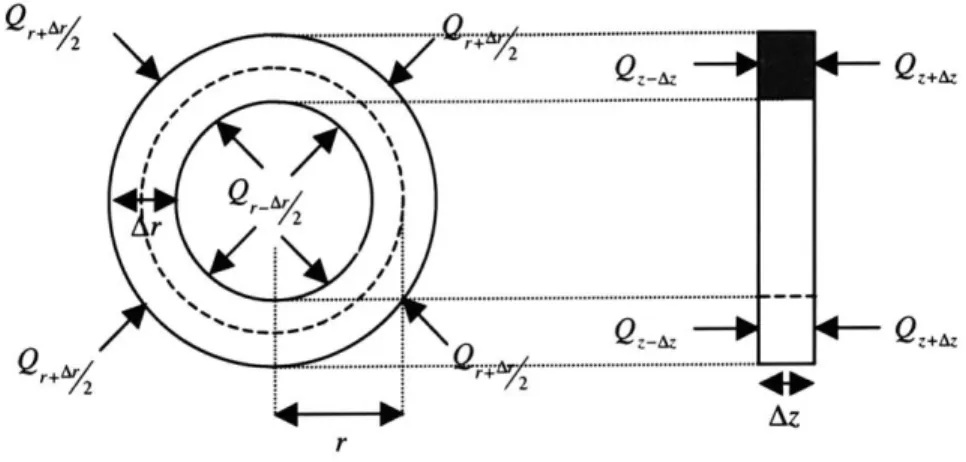
In order to achieve better accuracy in the calculations, a cylindrical coordinate system is used for the 2-D mesh in Figure 3-5, where the z-dimension represents the longitudinal direction in the runner system and the r-dimension represents the radial direction. Each cell denotes a mng element in the mesh. Details of this ring element shall be discussed in the following section.