HAL Id: hal-01117779
https://hal.inria.fr/hal-01117779
Submitted on 19 Feb 2015
HAL is a multi-disciplinary open access
archive for the deposit and dissemination of
sci-entific research documents, whether they are
pub-lished or not. The documents may come from
teaching and research institutions in France or
abroad, or from public or private research centers.
L’archive ouverte pluridisciplinaire HAL, est
destinée au dépôt et à la diffusion de documents
scientifiques de niveau recherche, publiés ou non,
émanant des établissements d’enseignement et de
recherche français ou étrangers, des laboratoires
publics ou privés.
Actor-based Runtime Model of Adaptable Feedback
Control Loops (Position Paper)
Filip Křikava, Philippe Collet, Robert France
To cite this version:
Filip Křikava, Philippe Collet, Robert France. Actor-based Runtime Model of Adaptable Feedback
Control Loops (Position Paper). Proceedings of the 7th International Workshop on models@run.time,
2012, Innsbruck, Austria. �hal-01117779�
Actor-based Runtime Model of Adaptable Feedback
Control Loops (Position Paper)
Filip Kˇrikava
Université Nice Sophia Antipolis, France
I3S - CNRS UMR 7271
filip.krikava@i3s.unice.fr
Philippe Collet
Université Nice Sophia Antipolis, France
I3S - CNRS UMR 7271
philippe.collet@unice.fr
Robert B. France
Colorado State University, USA
Computer Science Department
france@cs.colostate.edu
ABSTRACT
Engineering self-adaptive systems is a particularly challenging prob-lem. On the one hand, it is hard to develop the right control model that drives the adaptation; on the other hand, the implementation and integration of this control model into the target system is a difficult and an error-prone activity. Models@runtime is a promis-ing approach to managpromis-ing adaptations at runtime, as they provide higher levels of abstractions of both the running system and its en-vironment. However, recent work mainly focuses on runtime mod-els that are causally connected to running systems and less attention is paid to how models can be used to develop and manage the con-trol logic that drives runtime adaptations.
In this paper we propose an alternative form of models@runtime as a reactive data-driven model centered around feedback control loops. Both the target system and the adaptation logic are repre-sented as networks of message passing actors. Each of these actors represents a particular abstraction over the running system (sen-sors, effectors) and its control (analysis, decision). Moreover, the actors are also viewed as target systems themselves. This makes the feedback loops adaptable at runtime as well and permits us to build complex solutions with hierarchical layers of control loops. We discuss how this representation fits some of the requirements of models@runtime and helps to prototype a feedback control sys-tem on a concrete example extracted from ongoing validation case studies.
1.
INTRODUCTION
Being able to dynamically adjust software structure and behav-ior at runtime is increasingly becoming an important aspect of con-temporary software systems. Such self-adaptive systems are char-acterized by the ability to autonomously reconfigure themselves based on their perception of their state and their environment, usu-ally following some higher level user specified goals [3]. While these properties can make systems more robust and prone to fail-ures, their construction is a challenging engineering problem [2].
A key aspect of engineering such systems is the Feedback Con-trol Loop (FCL) as it provides the generic mechanism for self-adaptation [2]. A typical FCL consists of distinct phases of moni-toring and analyzing both the running system and its environment, followed by planning an subsequent execution of changes that alter the system state. Self-adaptive systems based on feedback control have been proposed, but their engineering is far from mature [17, 2]. Possible reasons are the difficulty of creating a control model
Copyright is held by the author/owner(s). MRT-12October 02 2012, Innsbruck, Austria. ACM 978-1-4503-1802-0/12/10.
[15, 10], and designing and implementing of the control mecha-nisms. The integration of control mechanisms into a target applica-tion is also a difficult and error-prone activity.
One of the promising approaches supporting development of such systems involves the use of models@runtime . This research aims at providing abstractions that facilitate automated management of runtime behavior [6]. The runtime models provide higher-level ab-stractions of both the running system and its environment and are also manipulated at runtime. However, the focus has been mostly on effecting changes through modifications to runtime models that are causally connected to running systems. Less attention has been paid to how runtime abstractions can be used to develop and man-age the control logic that drives runtime adaptations.
In this paper we propose an alternative form of models@runtime in which the model is a reactive data-driven model of feedback con-trol loops. The model is based on a runtime architecture that sep-arates the target of adaptation (e.g. a software system that can be observed and/or modified) from the control layer. Actors [11] are used to represent elements in the target system (e.g., sensors and ef-fectors) and the control layer (e.g., (analysis and decision-making mechanisms). It consists of configurations (networks) of actors rep-resenting the target system and control layers. Different forms of control can be obtained by linking actors in different ways. The ac-tor representation makes the FCL explicit through models at both design and run times. This explicit representation provides abstrac-tions that should make it easier to reason about the system and the correctness of interactions between different FCL elements. This is one of the main benefits of using a model to describe adaptation processes [21].
Moreover, by introducing reflective capabilities into this model we are able to observe and modify the actors and their configura-tions uniformly, in the same way as the running system. This makes the FCLs adaptable at runtime as well as the target system and thus enables one to build complex solutions in cases when there is a need for control coordination or hierarchical layers of control loops.
The rest of the paper is organized as follows. Section 2 gives background on the actor model. Section 3 presents an overview of our approach to constructing feedback control loops using the ac-tor model. It is followed by an illustration of this approach on a concrete example (Section 4). Section 5 positions our work with regards to the related work. Finally we discuss how this represen-tation fits models@runtime and its requirements together with an outline for further work in Section 6.
2.
BACKGROUND
The actor model provides a concurrent programming paradigm that is based on actor objects [11]. Actors are essentially
indepen-dent concurrent processes that encapsulate their state and behavior and communicate exclusively by exchanging messages. Messages are sent asynchronously and each actor maintains a queue of re-ceived messages (a mailbox) and processes them one-by-one.
Actors act independently of one another. In its core it is a sim-ple entity that can only receive, process and send messages. The actor states are stored within the actors themselves (states are not globally accessible). An actor can only manipulate its own state and never directly accesses the state of other actors, however, it can send a message that in turn may change the state of its recipient.
The model is inherently reactive. Each actor waits for messages in order to do its work. The task an actor performs upon message arrival is completely left for the user to specify. Different behav-iors can be associated to different messages and it can also include spawning new actors.
Actors are independent of threads. Different implementations can map threads to actors in different ways. It is possible to have more than one thread to execute one actor and similarly to have only one thread executing multiple actors. However, the actual message processing is always executed by one thread at the time and the messages must be immutable in order for the model to work cor-rectly.
Following are the most relevant features of actors in our context: 1. Thread safe. The actor model provides a notable advantage over the standard shared memory concurrency. Accessing an actor’s mailbox is by design race condition free. A lock free code is also simpler to write and maintain. It is important to note that actors are not dead lock free as it is possible to have two actors to wait for messages from each other.
2. Dynamic. Actors can create new actors.
3. Scalable. The actor model has a lower context-switching over-head over the standard shared-memory threads with locks, as well as a reduced memory footprint [8].
4. Distributed. The message-based concurrency with encapsulated state can be seen as a higher-level model for threads with the potential to generalize to distributed computation [8].
5. Available. Today, there exists several high-performing actor li-braries for mainstream programming languages1.
3.
ACTOR REPRESENTATION OF
FEEDBACK CONTROL LOOPS
In this section we present an overview of our approach that will be followed by a concrete example in the next section.
3.1
Overview
Our approach is centered around the concept of Feedback Con-trol Loop (FCL) and we use the actor model to represent it. Each actor in the model has one of the following roles that correspond to some aspects of a FCL.
Sensor. Collects raw information about the state of the system and its environment from observable entities like various operating sys-tem resources, service calls, user preferences, etc. A sensor can be either active or passive. An active sensor is used when the data up-date is based on some external event, like a file change or a timer. The actor itself is then responsible for attaching an appropriate lis-tener to be able to activate itself when the event occurs. A passive sensor, on the other hand, has to be explicitly activated by a mes-sage sent from another actor.
1http://goo.gl/WcXCE
Effector. Carries out changes on the target system. It can be seen as a parameterized operation that is executed in order to alter the state of the system.
Filter. Aggregates or filters data from one or more connected sen-sors, or other filters. They can be real data filters, stabilization mechanisms, converters, rule inference engines, etc. A typical ex-ample is a noise filter used to stabilize the data that comes from sensors and inferring some higher-level information.
Controller. Represents the decision making process. Essentially, it is responsible for choosing the appropriate action(s) among the set of all permissible actions based on the state of the running system that has been inferred by sensors and filters. There are many differ-ent types of controllers that can be employed. A good overview of some of the different control strategies can be found in [15]. The first two roles are related to the relevant abstractions over the running system and its surrounding environment (touch-points), the two others represent the adaptation logic.
The actual adaptive behavior is realized by connecting together corresponding actors (cf. Section 4.2) to form an acyclic directed network. It can be partitioned into layers: a system layer consist-ing of sensors and effectors that provide all the inputs and outputs necessary for the adjacent control layer to reason about and to ad-just the execution context of the running system represented by the system layer.
The different concerns of FCLs are separated and realized by one or more collaborating actors. The (1) data collection is re-alized by sensors, (2) analyzing is done by filters, (3) decision is taken by controllers, and (4) finally effectors are responsible for fi-nal changes execution. Since actors are independent entities, some of them could be reused in different systems. The primary mo-tivation of this separation of concerns is to allow for building the loops from composed rather than programmed entities, as well as to foster reuse of both the independent actors and partial or complete loops.
3.2
Model Reflection
The reflection support in the model is also realized using actors. We provide actors that represent the introspection and intercession capabilities of the actor runtime system. This includes effectors controlling the sensors life-cycle allowing to start new actors or stop the already running ones, changing message recipients, as well as active sensors sending notifications every time an actor changes its state (cf. Section 4.5).
Conceptually we can view any actor as a running system itself. We are therefore able to observe and modify its state using touch points similarly as with the running system. We use a special notion of provided sensors and provided effectors to implement this actor reflection. Technically, they are just ordinary sensors and effectors actors that use special messages to indirectly manipulate the state of other actors and together form another system layer of the control system (cf. Figure 3). They are logically bound to the context of other actors, parents, that are responsible for managing their life cycle.
Provided sensors are inherently active. They are notified by their parents every time their state has changed so the information can be further pushed into the control layer. This is important as it allows for assembling the control layer in a uniform way regardless of what system layer is being use.
This actor reflection is a crucial feature that permits to build com-plex solutions in cases when there is a need for control loops ordination or for organizing them into hierarchical layers. The co-ordination can be done by explicitly synchronizing controllers via
provided sensors (cf. Section 4.4). The hierarchical layering uses reflection to enable loops in one layer to be supervised by another loop in the adjacent higher-level layer (cf. Section 4.3).
Since both provided sensors and effectors are actors themselves, they can also be observed and modified using their provided sensors and effectors. However, in our studies and validations, we do not find more than two levels to be very useful.
3.3
Connection to the Running System
The connection between the touch point actors, i.e., sensors/-effectors, and the running system is realized using uni-directional causal links that use the introspective (sensing) and intercessory (effecting) capabilities of the provided system interfaces. While these abstractions might seem to be too low-level [19], they sim-plify the actual implementation of the execution code and system reasoning. Filters are employed to infer higher-level information from the sensor data. This way we can provide flexible abstractions based on the need of a particular controller for specific adaptation scenarios.
From an implementation perspective, the actual actor behavior, i.e. the executable code, is specified through a delegate that de-couples the actor related code from the user code. In practice this usually means creating a new class that complies to a certain in-terface depending on the target actor role. Since there is no need for any actor specific code in the delegate, it can be unit tested in isolation. It is also important to note that even though the delegate code might be used in highly concurrent environments, it does not have to be thread safe as it is only called by one thread at a time. This considerably simplifies the coding efforts required from the final developers.
3.4
Execution
The loop execution is driven by messages that are passed among actors. By design the actors are passive, they sit waiting for mes-sages to arrive. We use active sensors as a triggering mechanism for loop execution.
During its initialization, an active sensor registers itself to some external events. When an event occurs, it extracts the relevant in-formation and dispatches it to the corresponding actors (i.e., filters or controllers). This in turn initiates other messages before the ac-tual control code is executed. An example of the messages passing is given in the sequence diagram schema on Figure 2.
Consequently the reactive nature of the model results in less need for synchronization between the running system and the abstraction layer, since the introspection and intercession happen during the loop execution. However in some cases, implicit synchronization is inevitable. It is thus supported in the model (cf. Section 4.5).
4.
ILLUSTRATIVE CASE STUDY
4.1
Motivating Adaptation Scenario
We consider a High-Throughput Computing environment where users can log in an interface allowing them to execute scientific workflows using the Condor infrastructure [18]. Condor is a well-established distributed batch computing system that has been ex-tensively used in both academia and industry.
In Condor, a workflow is usually executed by running a DAG-Man that takes control of the jobs dependencies and submits the ready to be executed jobs to the Condor scheduling agent (schedd). The schedd is responsible for managing the queue of the user sub-mitted jobs and mapping them onto a set of resources where the actual execution is performed. By default schedd accepts all valid submissions requests regardless of the current state of the system.
Since especially scientific workflows tend to be large, it can be-come a bottleneck and potentially overloaded as the work it has to perform is proportional to the number of jobs that it controls. This in turn might result into an overall throughput degradation. There are a number of configuration options for both the scheduler and the workflow manager that allows for fine tuning the system behavior. However, all of them are statically defined, without considering the current state of the system.
Our objective is therefore to graft a control on top of the Condor job submission, which would ensure high throughput, while pre-venting the schedd overload. One way is to base the adaptation on a model that takes the number of jobs in the queue (N), together with a service rate (µ) and a number of executing DAGMans (m) to compute a delay (d) that is used to throttle workflow submission rates. This will help to keep the number of idle jobs within a cer-tain range for which the system performs well. More information about the control model together with some experimental results are given in [13].
4.2
Modeling Feedback Control Loops
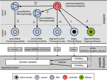
Figure 1 illustrates the actors and the message flow. It includes the causal links to the running system of one feedback control loop that implements the illustrative example using the control elabo-rated above. co n tro l syst e m la ye r co n tro l la ye r effector
active sensor sensor filter controller
$ ps timer ... ... submits Operating System ru n n in g syst e m Condor schedd
$ condor_q reads $SPOOL/history
DAGMan1 writes $SPOOL/dagman_delay DAGMann serviceRateAvg : MovingAverage queueStatAvg : MovingAverage serviceRate : CondorServiceRate dagmanCounter : ProcessCounter queueStats : CondorQueueStats dagmansDelayer : DagmansDelayer submissionRateCtrl : SubmissionRateCtrl trigger : PeriodicSignal
Figure 1: The actor model of the overload control example. The links between actors show the directions of messages and the labels denote what data are being transmitted. We use the notation of actorName : DelegateTypeto denote the names and the actual types of the actors delegates while the role is represented by icons.
The control loop is triggered by the trigger sensor that pe-riodically (every p seconds) notifies the connected controller by sending an arbitrary signal s. Before the controller can compute the delay d, it needs to gather required data from the connected sensors:
1. The queueStats provides the information about the number of jobs in the queue N using the condor_q command, 2. the current service rate µ comes from the condor history file and
is extracted by the serviceRate, and
3. the number of running DAGMan processes m is obtained from the dagmanCounter by executing the system ps command. In order to increase the stability of data and avoid oscillation, the
Nand the µ inputs are filtered using moving average filters before they enter the submissionRateCtlr. We do not need to filter the number of DAGMans m since workflow executions are usually long running processes. Once all the inputs have been gathered the controller, using the formulas elaborated in [13], computes the delay d that will be imposed system wide to all running DAGMans by the dagmansDelayer. In this example it is simply written into a file from which it is read by DAGMan the next time it tries to submit a job.
While some of the actors identified are use-case specific such as the submissionRateCtrl, others could be reused in some dif-ferent Condor related control systems. One of our ongoing long term goal is to initiate a library of reusable FCL elements and pat-terns, both at the model and implementation levels.
serviceRate
dagmansCounter queueStat dagamnsDelayer submissionRateCtrl trigger delegate() delegate() delegate() delegate() delegate() delegate() timer
Figure 2: Excerpt of the message sequence for the control exam-ple from Figure 1. For simplification, we omit the filters. The delegate()call represents the execution of the actual user code. The Figure 2 shows a translation of the actor schema into a se-quence diagram representing the actual message passing chain. The messages are all sent asynchronously. This is thus the only in-stance of the possible execution sequence. The submission-RateCtrlcan receive responses from the connected sensors in different order.
4.3
Hierarchy of Feedback Control Loops
The primary concern in the above overload control was to protect an unbounded usage of the schedd submission service. The prob-lem is that the protection of one resource might in consequence jeopardize another and thus transform one problem into a differ-ent and potdiffer-entially much worse one (as it might be unexpected). Therefore, in general, this process has to be done recursively for any potential unbounded resource usage, regardless whether it is a system resource or a service usage.
In our solution this problem is related to the queueStats sen-sor. Internally it executes condor_q command that makes the schedd walk its entire job queue, which becomes an expensive op-eration when the number of jobs is large (this behavior is internal to Condor). One way to fix this is by adding a new control layer on top of the existing one that will throttle the execution frequency of the queueStats sensor.
The new control schema is depicted in Figure 3. First we extend CondorQueueStatsto provide information about how long it took the last time to execute condor_q using a provided sensor
me ta -co n tro l syst e m la ye r co n tro l la ye r setPeriod execTime execTimeAvg
: MovingAverage : TriggerRateCtrltriggerRateCtrl
co n tro l syst e m la ye r co n tro l la ye r serviceRateAvg : MovingAverage queueStatAvg : MovingAverage serviceRate : CondorServiceRate dagmanCounter : ProcessCounter queueStats : CondorQueueStats dagmansDelayer : DagmansDelayer submissionRateCtrl : SubmissionRateCtrl trigger : PeriodicSignal
Figure 3: Example of Feedback Control Loops hierarchy. The ac-tual control and running system is the same as in Figure 1. execTime. Next we add a provided effector setPeriod to the PeriodicSignalsensor that allows for adjusting the triggering period p. Finally, in the new meta-control layer we create a con-troller that adjusts the execution frequency proportionally to the execTimetime.
4.4
Coordination of Feedback Control Loops
Actor reflection is also used for coordinating multiple interacting loops using an explicit synchronization. For example when one controller reaches a certain state, it can use a provided sensor to signal it to another controller that then performs its own work.
The following figure 4 shows how a possible coordination sce-nario can be implemented from our overload control use case.
co n tro l la ye r co n tro l submissionRateCtrl : SubmissionRateCtrl resetHistory : CondorHistoryReset
Figure 4: Example of feedback control loops coordination. The ∅ denotes no notification.
The submissionRateCtlr might observe that the service rate measures are somehow corrupted and explicitly requests a re-pair loop to be executed. It notifies the provided sensor S1which
will indirectly trigger the resetHistory, which will try to fix the situation.
Like with any other synchronization, some of the technical de-tails have to be handled, for instance: What should happen if the repair loop takes too long to execute and the submissionRate-Ctrlhas executed in the meantime, still finding the value to be corrupted? What will happen if, by the repair action, the service-Ratesensor crashes? Since often the solutions to these issues are case specific, the model itself does currently not provide any spe-cial support. They have to be resolved manually. However, we are currently investigating how one can express these concerns more explicitly.
4.5
Implicit Synchronization
In the presented control system we use one actor that represent all the running workflow managers. When a new delay is computed and pushed it affects all running DAGMans. Since we use only one global delay, this is a correct abstraction. However, we can imagine to have a more complex control that will compute different
delays for different DAGMans, therefore needing to represent each running DAGMan explicitly as an actor.
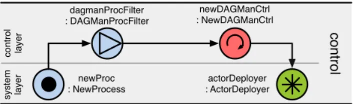
syst e m la ye r co n tro l la ye r newProc : NewProcess co n tro l dagmanProcFilter : DAGManProcFilter actorDeployer : ActorDeployer newDAGManCtrl : NewDAGManCtrl
Figure 5: Example of an implicit synchronization of running DAG-Man processes
Figure 5 depicts a control loop that can be used for an implicit synchronization between a running system and its runtime abstrac-tion. The newProc sends out a notification every time a new cess has been started. In the filter DAGManProcFilter, pro-cesses that are not DAGMans are filtered out and the others are pushed to a controller that uses the actorDeployer to spawn a new actor of an appropriate role, type and configuration. Of course a similar loop needs to be built for stopping actors whose underly-ing DAGMan has finished execution.
5.
RELATED WORK
IBM proposed a form of standardized approach for the feedback loops with the Monitor-Analyze-Plan-Execute-Knowledge (MAPE-K) architecture [12]. Several systems and frameworks have been developed according to this principle. For example, the Rainbow architecture [7] consists of two-layer framework with an external fixed control loop. While the loop is made explicit, the framework is not explicitly reflective and therefore it does not support hierar-chical FCLs.
The Genie domain specific modeling tool [1] uses architectural models to support generation and execution of adaptive systems for component-based middleware technologies. The adaptive logic is specified as state machines. Similarly, the DiVA project [16] also uses architectural models for dynamic adaptation, together with modeling some other aspects such as variability, system, context and adaptation logic. It employs MDE techniques to produce re-configuration scripts that performs the actual adaptation. In our approach we rather focus on a more general and explicit feedback control loop modeling framework.
In [20] Vogel et al. promotes the use of runtime executable meg-amodels. They present a modeling language for adaptation logic modeling together with a runtime interpreter that executes the meg-amodels. Similarly to our approach they can also represent loop coordination and hierarchically organize them into layers. How-ever, while they provide illustration of coordination and layering of different adaptation strategies, there is only a high-level overview of how the actual adaptations look like. On the contrary our model provides a concrete runtime representation of a feedback control loop. Their solution relies on an implicit synchronization between the runtime megamodels and running system. The metamodel is based on EMF that has some limitations for the use at runtime such as higher memory footprint, lack of thread safe access to the model [5].
In [9] Hebig et al. provide a UML profile to explicitly archi-tect several coordinated control loops with component diagrams. Nevertheless the loop elements are not adaptive and it does not ex-plicitly show the adaptation flow. There is also no connection to a runtime support.
As for control, in [14], Litoiu et al. describe a hierarchical frame-work that accommodates scopes and timescales of control actions,
and different control algorithms. Their architecture considers three main types of controllers reflecting the three different stages that they focus on: tuning, load balancing, and provisioning. While being similar, our architecture is more general, but provides less fine-tuned building blocks to control the behavioral models used inside controllers.
There is also a large body of work that concerns designing feed-back control for embedded computing, for example Ptolemy II [4]. We have a similar actor-based approach whose execution seman-tics is comparable with Ptolemy’s component interactions model of computation. We need to further investigate the main assump-tions and differences between these systems so to determine the possibility of reuse, i.e. being able to generate Ptolemy II model from our actor model.
Similar approach could be realized using more traditional reflec-tive component model. However, in such a case next to the com-ponent styles that would correspond to our actor roles, one would also have to define an execution semantics (the component states, states’ transitions and model of computation).
6.
DISCUSSION
In this section we discuss how our proposal fits in the landscape of models@runtime and the overall goal of FCL engineering for self-adaptive software systems. We also give an overview of ongo-ing and further work.
6.1
Towards Models@runtime
Even though it is not a typical approach to models@runtime we believe that the proposed solution is a possible and pragmatic approach towards realizing feedback control systems. The actor model provides a higher-level abstraction of a running system that is manipulated at runtime to dynamically adapt the underlying sys-tem. The concern is whether the proposed abstraction is expressive and intuitive enough to support activities of runtime software adap-tations based on feedback control.
To validate this point we need to conduct more experiments and design self-adaptive systems across different domains. However, the preliminary results already show the following major benefits that considerably ease development: (1.) it provides an explicit and concrete representation of FCLs described in the actor model, (2.) the adaptation in form of FCLs is specified at a higher-level of abstraction by a network of cooperating actors, (3.) each actor is an independent unit that can be used in different adaptation contexts, (4.) the reflection capabilities of the model allows the actors to be adapted at runtime in a uniform way, and (5.) multiple coordinated and hierarchically layered FCLs can be expressed in a uniform way. Moreover, we find actors actor to be a particularly suitable model, as it directly supports some of the main non-functional require-ments of models@runtime [5]. Thread safety, offered by design, results in potentially more secure and easier to implement execu-tion code. Since the actors encapsulate their state and communi-cates only by sending asynchronous messages, they are suitable for distributed environments. The actor model is designed to be scal-able and lightweight. For instance in the Akka2 2.0 the memory
overhead is about 400 bytes per instance ( 2.7 million actors per GB of heap) with a possible throughput of 50 million messages per sec on a single machine3. This combined with many actor model implementations available today enable one to deploy the proposed solution on top of a significant range of systems.
2http://akka.io
3http://doc.akka.io/docs/akka/2.0.2/intro/
6.2
Towards Rapid Prototyping
The model elaborated in this paper is now being integrated into our Model-Driven Engineering toolkit ACTRESS4. Its aim is to use modeling techniques to provide engineers and researchers with a tooled approach that would help them to rapidly prototype and experiment with self-adaptive systems, putting quickly their ideas into practice. The approach needs to be built on a flexible abstrac-tion and must cope with the diversity and heterogeneity of current platforms, while being efficient in performance.
The system is currently being implementated in Scala5using the
aforementioned Akka framework. From the initial results the actor model seems a suitable abstraction that performs well, but empiri-cal evidence and wider usage are still missing. Besides it must be noted that the model itself is technologically agnostic. Other lan-guages and frameworks can be used to target different classes of systems.
6.3
Ongoing and Future Work
The proposed approach is currently under validation inside the ANR-funded SALTY project6. Ongoing work on this project
use-cases (e.g., regulation of a geo-tracking system following fleets of thousands of trucks) will complement validation by providing more thorough experience of applying the proposed approach. We are currently in the process of making the implementation stable with a comprehensive set of unit tests over the modelling support. How-ever the complete MDE tool chain is still at the prototype level.
Further, we need to work on the composition of actors and how to express some of the concerns related to loop coordination and failure propagation.
Acknowledgments
The work reported in this paper is partly funded by the ANR SALTY project under contract ANR-09-SEGI-012.
7.
REFERENCES
[1] N. Bencomo, P. Grace, C. Flores, D. Hughes, and G. Blair. Genie: supporting the model driven development of reflective, component-based adaptive systems. In Proceedings of the 13th international conference on Software engineering - ICSE ’08, ICSE, page 811, New York, New York, USA, 2008. ACM Press.
[2] Y. Brun, G. Di Marzo Serugendo, C. Gacek, H. Giese, H. Kienle, M. Litoiu, H. Muller, M. Pezzè, and M. Shaw. Engineering Self-Adaptive Systems Through Feedback Loops. Software Engineering for Self-Adaptive Systems, pages 48–70, 2009.
[3] B. Cheng. Software Engineering for Self-Adaptive Systems: A Research Roadmap. In Software Engineering for Self-Adaptive Systems, volume 5525, pages 1–26. Springer Berlin / Heidelberg, 2009.
[4] J. Eker, J. Janneck, E. Lee, J. Ludvig, S. Neuendorffer, and S. Sachs. Taming heterogeneity - the Ptolemy approach. Proceedings of the IEEE, 91(1):127–144, Jan. 2003. [5] F. Fouquet, G. Nain, B. Morin, E. Daubert, O. Barais,
N. Plouzeau, and J.-M. Jézéquel. An Eclipse Modelling Framework Alternative to Meet the Models@Runtime Requirements. In Models 2012, 2012.
[6] R. France and B. Rumpe. Model-driven Development of Complex Software: A Research Roadmap. In Future of Software Engineering, 2007.
4https://nyx.unice.fr/projects/actress 5http://www.scala-lang.org/
6https://salty.unice.fr
[7] D. Garlan, B. Schmerl, and P. Steenkiste. Rainbow: architecture-based self-adaptation with reusable infrastructure. In Proceedings of the 2004 International Conference on Autonomic Computing, 2004, 2004. [8] P. Haller and M. Odersky. Scala Actors: Unifying
thread-based and event-based programming. Theoretical Computer Science, 410(2-3):202–220, Feb. 2009. [9] R. Hebig, H. Giese, and B. Becker. Making control loops
explicit when architecting self-adaptive systems. In Proceeding of the second international workshop on Self-organizing architectures - SOAR ’10, SOAR, page 21, New York, New York, USA, 2010. ACM Press.
[10] J. Hellerstein, Y. Diao, S. Parekh, and D. Tilbury. Feedback control of computing systems. Wiley Online Library, 2004. [11] C. Hewitt. Viewing control structures as patterns of passing
messages. Artificial Intelligence, 8(3):323–364, June 1977. [12] J. Kephart and D. Chess. The vision of autonomic
computing. Computer, 36(1), Jan. 2004.
[13] F. Krikava and P. Collet. A Reflective Model for Architecting Feedback Control Systems. In Proceeding of the 2011 International Conference on Software Engineering and Knowledge Engineering, Miami, 2011.
[14] M. Litoiu, M. Woodside, and T. Zheng. Hierarchical model-based autonomic control of software systems. In Proceedings of the 2005 International Workshop on Design and Evolution of Autonomic Application Software (DEAS ’05), page 1, New York, New York, USA, 2005. ACM Press. [15] M. Maggio, H. Hoffmann, M. D. Santambrogio, A. Agarwal,
and A. Leva. Decision making in autonomic computing systems. In Proceedings of the 8th ACM international conference on Autonomic computing - ICAC ’11, ICAC ’11, page 201, Karlsruhe, Germany, 2011. ACM Press.
[16] B. Morin, O. Barais, J.-M. Jezequel, F. Fleurey, and A. Solberg. Models@ Run.time to Support Dynamic Adaptation. Computer, 42(10):44–51, Oct. 2009. [17] M. Salehie and L. Tahvildari. Self-adaptive software:
Landscape and research challenges. ACM Transactions on Autonomous and Adaptive Systems (TAAS), 4(2):1–42, 2009. [18] D. Thain, T. Tannenbaum, and M. Livny. Distributed
computing in practice: The Condor experience. Concurrency and Computation Practice and Experience, 2005.
[19] T. Vogel and H. Giese. Adaptation and abstract runtime models. In Proceedings of the 2010 ICSE Workshop on Software Engineering for Adaptive and Self-Managing Systems, New York, New York, USA, 2010.
[20] T. Vogel and H. Giese. A Language for Feedback Loops in Self-Adaptive Systems: Executable Runtime Megamodels. In 7th International Symposium on Software Engineering for Adaptive and Self-Managing Systems (SEAMS), number 3 in SEAMS, pages 129–138. IEEE, June 2012.
[21] J. Zhang and B. H. C. Cheng. Model-based development of dynamically adaptive software. In Proceeding of the 28th international conference on Software engineering - ICSE ’06, New York, USA, 2006.