HAL Id: hal-01117775
https://hal.inria.fr/hal-01117775
Submitted on 17 Feb 2015
HAL is a multi-disciplinary open access
archive for the deposit and dissemination of
sci-entific research documents, whether they are
pub-lished or not. The documents may come from
teaching and research institutions in France or
abroad, or from public or private research centers.
L’archive ouverte pluridisciplinaire HAL, est
destinée au dépôt et à la diffusion de documents
scientifiques de niveau recherche, publiés ou non,
émanant des établissements d’enseignement et de
recherche français ou étrangers, des laboratoires
publics ou privés.
A Reflective Model for Architecting Feedback Control
Systems
Filip Křikava, Philippe Collet
To cite this version:
Filip Křikava, Philippe Collet. A Reflective Model for Architecting Feedback Control Systems.
Pro-ceedings of the 23rd International Conference on Software Engineering and Knowledge Engineering,
2011, Miami, United States. �hal-01117775�
A Reflective Model for Architecting Feedback Control Systems
Filip Kˇrikava
Universit´e Nice Sophia Antipolis
I3S - CNRS UMR 6070, Sophia Antipolis, France filip.krikava@i3s.unice.fr
Philippe Collet
Universit´e Nice Sophia Antipolis
I3S - CNRS UMR 6070, Sophia Antipolis, France philippe.collet@unice.fr
Abstract—Autonomic Computing aims at realizing comput-ing systems that are able to adapt themselves, but the engineer-ing of such systems in the large is rather a challengengineer-ing task. It is hard to find an appropriate model that controls the adaptation itself and several loops are likely to be coordinated to avoid unexpected and harmful behaviors. This paper presents an approach and a runtime support to architecture self-adaptive systems, in which each part of the feedback control loop is uniformly and explicitly designed as a first-class adaptive element. Making these elements explicit allows the architect to reason about system modeling and to reuse them. Code generation from the architecture model avoids painful details of low-level system implementation.
Keywords-Autonomic Computing, Model-Driven Engineer-ing, Software Architecture
I. INTRODUCTION
The 24/7 deployment of distributed systems is dramati-cally increasing the complexity and maintenance costs of software systems. The ability to adapt then becomes crucial for such systems. Autonomic computing is a promising way to organize self-adaptive systems. This approach aims at realizing computing applications that can dynamically adjust themselves to accommodate changing environments and user needs with minimal or no human intervention [1]. The engineering of such systems in the large is rather a challenging task. It is hard to find an appropriate model that controls the adaptation itself [2]. Its implementation being generally integrated in a feedback control loop, developing several adaptive behaviors necessitates to reason on them, at least to obtain an appropriate coordination between them. Moreover, engineering in the large obviously needs some reuse capabilities on loops or more likely, on elements composing the loops [3].
Following the general principle that control loops should be made explicit [4], [5], we present in this paper an approach for engineering self-adaptive systems with an explicit architectural model and its runtime support. In the proposed architecture each part of the feedback control loop is uniformly and explicitly designed as a first-class adaptive element. Making these elements explicit allows the architect to reason about system modeling, while capturing different patterns of interactions and controls (coordination of loops, adaptive monitoring, etc.). By applying a model-driven ap-proach with a framework based on standardized interfaces,
loops and loop elements are then likely to be more easily reused. Moreover code generation from the architecture avoids painful details of low-level system implementation.
The remainder of this paper is organized as follows. Section II introduces some background on autonomic control loops and discusses requirements. Our approach is described in Section III, giving details of its principles and archi-tectural model. Section IV illustrates our proposal on an overload scenario of an extensively used distributed batch computing system. The runtime support is also presented, and first experimental results are evaluated. Some related work are discussed in Section V. Finally, we conclude and briefly present future work in Section VI.
II. ENGINEERINGSELF-ADAPTIVESYSTEMS
Self-adaptive systems are characterized by runtime de-cisions to control their structure or their behavior and making these decisions autonomously (i.e. without or with minimal interference) while reasoning about their contexts and environments [5]. Self-adaptive software is generally organized around closed feedback loops aiming at adjusting itself during its operation. The Autonomic Computing refers to self-managing characteristics of computing resources that manage themselves given some high-level objectives by adjusting their operation in the face of changing environment and user needs [1].
Making autonomic computing a reality necessitates to put together and evolve results from several research dis-ciplines, from Artificial Intelligence (planning, decision the-ory, machine learning, agents, etc) to Control Theory and engineering [6], [3]. Moreover numerous challenges are directly related to the software engineering of feedback control loops, to ease the application of other disciplines. Loops have been originally designed following the sense-plan-actcontrol decomposition, or refined to make four steps appear, i.e. collect, analyze, decide, act. When engineering such loops, it has been first shown that it is hard to find an appropriate model that controls it [2]. Besides, building the software artifacts around this control model is far from being trivial, as monitoring data must be consistently collected and actions on the adapted systems well coordinated. Finally, overlapping in all concerns of a loop may appear when
several feedback loops need to be deployed, leading to unexpected and potentially harmful behaviors.
Previous work tackle these challenges. IBM proposed a form of standardized approach for the feedback loops with the Monitor-Analyze-Plan-Execute-Knowledge (MAPE-K) architecture [1], [7]. This makes explicit the behavior of autonomic managers which activity follows the M-A-P-E decomposition using some shared Knowledge (indicators, policies, plans...). Several systems and frameworks have been developed according to this principle [8], [9], [10]1, generally aiming at providing an architecture to organize the self-adaptive part. For example, Garlan et al. [9] proposed two-layers framework with an external fixed control loop that can be customized. The controlled and control system are clearly separated and a mapping allows data to be transmitted between them. The control loop is then made explicit but several feedback behaviors cannot be separately designed.
Recently, it has been advocated that control loops and their elements must be explicit to facilitate reasoning about them as well as their reuse [4], [5]. Even if recent work made some advances, with hierarchical MAPE-K coordi-nation [11] or component-based analysis architecture [12], there is, to the best of our knowledge, still the need for an ar-chitecture that would provide the right abstractions for rapid prototyping, but yet remain flexible enough to cope with the diversity and dynamic aspects found in current systems. In our vision, such architecture should support i) several kinds of loop element grouping and loop architectures, so that different forms of coordination between loops can be designed together with some sharing between monitoring elements or effectors on the controlled system; ii) adaptive capabilities over the controlled system but also on the control system, so that the architecture would capture adaptations over the monitoring, parameterizations on the models used by the controllers, etc. Moreover, the architecture should be versatile enough to capture the relevant parts of the feedback systems while being as abstracted from technological details as possible. In reusing some generative approach, this would foster reuse while avoiding painful details of low-level system implementation for most parts.
III. APPROACH
In this section we present the main principles of the pro-posed approach, together with the model for the architecture. A. Principles
In our approach, we focus on an externalized self-adaptation that is based on a closed loop feedback control. We express an architecture of such a self-adaptive system in a technologically agnostic model that is centered around the notion of a feedback loop and where each of the loop’s
1See [5] and [6] for surveys.
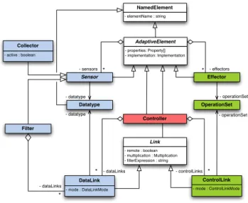
Effector Datatype Sensor OperationSet * * * - dataLinks * - datatype - operationSet * - datatype - operationSet NamedElement - elementName : string AdaptiveElement - properties: Property[] - implementation: Implementation Collector - active : boolean Filter DataLink - mode : DataLinkMode Link - remote : boolean - multiplication : Multiplication - filterExpression : string ControlLink - mode : ControlLinkMode Controller - dataLinks - controlLinks - effectors - sensors
Figure 1: Architectural model.
elements is made explicit [4]. Four main elements represent the main responsibilities in the feedback control. The target system and its context observability is captured in sensor elements, the decision making process is represented by con-troller elements and the actual system adaptation is carried out by the effector. We also explicitly model the data and control flow in the architecture via links that represent the dependencies between the components. Figure 1 presents the resulting architectural model. In the following paragraphs, we detail the different modelling capabilities of our proposal to design the different elements of a loop.
One of the main originality of the model is that it supports reflective self-adaptation. In the model, each element inherits from adaptive element, which itself can provide its own sensors and effectors. This feature allows elements to be introspected (meta-data, state) and modified in the very same way as the target controlled system is. One can hierarchically compose not only control on the top of controllers, but also on the top of sensors, effectors and links. The added adaptation then becomes self-adaptable as well, and in an uniform way. This notably distinguishes the model from other model-driven proposals [15]. In this paper, we do not deal with the distribution of loops and loop elements, but in that case, as links can be themselves adaptive, remoting issues like the inevitable delays and network failures could be addressed with our architectural model.
Besides, by using a model to express the adaptation con-cerns it allows us to support different degrees of separation in respect to the target system. From being completely external, running aside the target system in its own runtime platform, to be completely integrated inside the system using aspect-oriented techniques or direct source code generation. The model is technologically agnostic thus it only captures
the semantic of the adaptation: the definition of the com-ponents and with relevant inputs and outputs for data and control flow respectively.
B. System Observation
The monitoring part of the model (left part in fig. 1) is responsible for supplying information about the system into controllers so they can reason about the state of the system and its environment in order to take the appropriate decisions. This information is provided by hierarchically organized sensors elements in a form of a directed acyclic graphs with data links connecting them together. There are different types of sensors: collectors and filters.
Collector: The leaf nodes in the hierarchy are called collectors. A collector provides data of a defined datatype that are directly gathered from an external entity like various operating system resources, services calls, user preferences, etc. Essentially, it can operate in two modes: active or passive. An active collector is responsible for updating itself. This is used in cases where the update is based on some external notifications like a file change, new socket connection, etc. A passive collector, on the other hand, waits until it is explicitly requested by an associated link to provide data.
Filter: The other nodes in the graph, which are not leaves, are filters. These sensors are used to aggregate or in some other way process data that are coming from one or more connected sensors. They can be real data filters, stabilization mechanisms, converters, rules inference engines, etc. A typical example of a filter is a noise filter that is used to stabilize the context information that comes from other sensors. Since each filter is therewith an adaptive element, its parameters can be advertised using specific sensors and effectors, thus providing a uniform means to adjust them at runtime.
Each of the data links connects a producing node (a sensor) with consuming node (a filter or a controller) and can be configured before and at runtime to be operating in different modes. With periodic notification or observation (d, b) a link requests, at a fixed rate, the producer to get data and forwards it to the consumer. With reactive notification(4) a link is explicitly requested by a producer to forward given data to the connected consumer. Reactive observation (2) is the opposite of the notification, a link is explicitly requested by a consumer to get data from the connected producer.
When all elements of the monitoring part are connected, the model can easily be checked against the well-formedness of the resulting data flow (non-interrupting, correct typing). As the model relies on strong typing, the controller (through its data link) and its sensors must have compatible data types in order to be connected. The resulting data flow itself logically originates in collectors and terminates in controllers, however, the actual data transfer that triggers
the adaptation is driven by either active collectors or the periodic links. These are the only entities in the system that are actively running, the rest of the system is event based.
The links themselves supports adaptation so that their transmission properties, such as the notification or observing periods, are advertised and can be used by other loops. For example it can be used to model some adaptive monitoring or to handle timeouts on remote links.
C. Decision Making
The decision making part is in the model represented by the controller element. Essentially, the idea behind the decision making is to choose an appropriate action among the set of all permissible actions based on the observed state of the subjected system. There are many different kinds of controllers that can be used for the decision making process. A good overview of the some strategies is given in [13], but different kinds of controllers can be designed, for example supporting a decomposition between the analysis and planning phases, like in the MAPE-K decomposition [1]. In this paper we are not concerned by the actual design of the adaptation behavior itself, but rather we focus on supporting the architecture of the system as a whole.
D. System Alteration
The actual system modification is carried out by effectors that are orchestrated by controllers based on the actual decisions. An effector encapsulates a set of operations and provides them to the controlling elements via control links. An operation is a named action that can take an arbitrary number of arguments. Similarly to the data links, control links also use strong typing.
IV. ILLUSTRATION
In this section we illustrate our approach with a simpli-fied feedback based overload control system in the high-throughput computing domain.
A. Scenario Overview
We consider an environment made for executing compute-intensive scientific workflows [14] with the Condor infras-tructure [16]. Condor is a well established distributed batch computing system that has been used extensively in both academia and industry. We use a typical Condor deployment with one scheduler, a schedd agent, that is responsible for managing user submitted jobs and mapping them onto a set of resources where the actual execution is performed. Condor default support for executing workflow is provided by DAGMan (Directed Acyclic Graph Manager) execution engine, which acts as job meta-scheduler on the top of Condor batch system. Each workflow execution starts a new instance of the DAGMan that carries out the actual submission of the tasks into the schedd agent.
Since especially scientific workflows tend to be rather large, containing many computer-intensive tasks, the sched-uler can easily become overloaded, as the more tasks it has to handle the more resources it uses. The default behavior of the schedd is to accept all valid submission requests regardless the current state of the system. There are configuration options for both schedd and DAGMan, but they are static and do not take into account the current state of the system nor the number and nature of workflow executions varying over time.
B. Overload Control
In order to maintain a certain utilization of the system and prevent its overload, we design a basic controller that will be integrated in our illustrative self-adaptive architecture. The control maintains a certain number N∗of jobs in the queue. There is a configuration option in DAGMan that controls the number of seconds it waits before submitting a task. By making this option reread at before each submission we can impose an adjustable delay d for each client. We denote m the number of clients representing the DAGMan instances at some sample time t. Each client is submitting at rate λi=d1 therefore the total arrival rate at t is λ = ∑mi=11d=
m d.
The control optimizes the utilization of the queue ρ = λ µ
depending on the number of jobs N in the queue where µ is service rate. We use three cases for the state of N: if N= N∗then the buffer is ideally filled so we only maintain the λ = µ; if it is less, we linearly increase the arrival rate and when it is more we vigorously decrease it all the way to 0 shall N = Nc. The Nc> N∗denotes some critical number
of jobs in the queue that must not be reached.
ρ (N) = ρ0+N(1−ρN∗ 0) for 0< N < N∗, ρ0> 1 1 for N = N∗ α (N − Nc)p for N> N∗, where α =(N∗−N1 c)p From the utilization and total arrival rate we can derive the target delay d:
ρ (N) =λ µ = m d µ d= m ρ (N)µ
The ρ0denotes the maximum growth rate allowed in the
system. C. Architecture
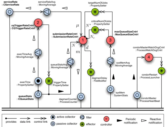
In figure 2 we present the resulting architecture using a graphical domain specific language. To increase readability, the names of the implementation classes have been added to the model while removing the names of links.
The first controller (1) is responsible for the submis-sion rate control elaborated above. It thus requires three inputs: the current number of jobs N provided by the queueStatscollector and further stabilized by a moving average filter, an information about the current service rate
µ that is coming from the serviceRate collector also stabilized, and the number of clients m is obtained from the dagmanCountercollector. The control output is linked to the dagmanDelayFile effector which simply writes the given delay to the appropriate file to make it available to the running DAGMans. The queueStats collector internally executes the condor_q command and parses its output. However, the more jobs are queued the longer it takes to execute and the more system resources it uses. In order to control it, we make this monitoring part self-adaptive as well by adding the controller (2) that adapts the trigger period of the link towards the controller (1) based on the average time that it takes to execute. Using again the self-adaptive capabilities of each adaptive element, we make the properties of the model in controller (1) i.e. the target number of jobs in the queue N∗and the critical number of jobs Nc, changeable
over time. In our simplified case, it is only dependent on the system memory. The controller (3), running at a slower pace, is responsible for controlling these properties.
Finally, in Condor there is a condor_master daemon responsible for keeping all the rest of the Condor daemons running. If it crashes, the pool looses its managing authority and has to be restarted. In our model, this can be done easily by adding a controller that gets its input from a process heartbeat sensor and start the process if it is not running anymore. Similarly to the master daemon, it uses an exponential back off delay before each attempt. While not being coordinated with other loops in this simplified version, several behaviors are currently added and coordinated with our approach. They can then be used to provide high-level indicators or notifications to system administrators. The overall system shows some relevant capabilities of our model to explicitly design various feedback control loops and self-adaptive behaviors on loop elements themselves. Some potentially reusable parts are also shown, with monitoring filters or loop patterns (adaptive monitoring, parameteriza-tion of the controller).
D. Implementation
Our current runtime support is based on the Equinox OSGi framework2. In this runtime each instance of an element from the model, including links, is registered as an OSGi service. For each dependency a proxy is generated. Upon request, it consults the OSGi service registry to locate the concrete instances. This allows us to employ the whiteboard pattern [17] for handling the data and control flow in the system. For example, instead of registering a listener for each reactive link to the respective elements, the link itself is registered as an OSGi service with appropriate service properties, so that the proxy can discover it and call when a notification or observation is needed.
control link data link provides id effector controller queueStats : CQueueStats sysMem : SystemStats 3 4 dagmanDelay : FileModifier condorMaster : ProcessHeartBeat queueStatsAvg : MovingAverage condorRestart : ProcessLauncher execTime : PropertyGetter serviceRate : CServiceRate 1 2 sysMemAvg : MovingAverage triggerTime : PropertySetter execTimeAvg : MovingAverage targetNumOfJobs : PropertySetter Periodic notification Reactive notification submissionRateCntrl : SubmissionRateCntrl maxQueueSizeCntrl : MaxQueueSizeCntrl cqTriggerRateCntrl : CQTriggerRateCntrl serviceRateAvg : MovingAverage condorMasterWatchDogCntrl : ProcessWatchDogCntrl criticalNumOfJobs : PropertySetter dagmanCounter : ProcessCounter
µ
N∗ Nc Nm
d
active collector passive collector filterFigure 2: Architecture of the WMS overload scenario. The names of the links are omitted. Each element also contains its corresponding implementation type. In case of controller (1) also the individual inputs and outputs are marked.
In order to turning the architecture into a running sys-tem, we first need to formally describe the model of the architecture from the fig. 2. We use a Domain Specific Language (not shown in this paper) that defines both the type model and the concrete instances together with values for all required properties and parameters needed at runtime. Additionally we need to provide an implementation for all the custom sensors, controllers and effectors (see elements marked bold in the figure 2). The rest are general reusable elements provided by our framework for the runtime support. Listing 1 shows an excerpt of a custom controller. This generated Java class skeleton is used as a delegate for the DelegatingController provided by the framework. This controller is responsible for handling the observation and notification of the data and control links and providing all the necessary inputs for the annotated control method of the delegate. p u b l i c c l a s s S u b m i s s i o n R a t e C o n t r o l l e r { . . . @ControlMethod p u b l i c v o i d c o n t r o l ( @ D a t a I n p u t( ” q u e u e S t a t s ” ) i n t q u e u e S t a t s , @ D a t a I n p u t( ” s e r v i c e R a t e ” ) f l o a t s e r v i c e R a t e , @ D a t a I n p u t( ” d a g m a n C o u n t e r ” ) i n t d a g m a n C o u n t e r , @ C o n t r o l O u t p u t( ” w r i t e r ” ) F i l e M a n i p u l a t i o n w r i t e r ) { . . . } @ P r o v i d e d E f f e c t o r ( ” t a r g e t N u m O f J o b s ” ) p u b l i c v o i d s e t T a r g e t N u m O f J o b s ( i n t t a r g e t N u m O f J o b s ) { . . . } @ P r o v i d e d E f f e c t o r ( ” c r i t i c a l N u m O f J o b s ” ) p u b l i c v o i d s e t C r i t i c a l N u m O f J o b s ( i n t c r i t i c a l N u m O f J o b s ) { . . . } . . . }
Listing 1: Excerpt of controller (1) implementation Once we have the model in the DSL and an implementa-tion of all the elements, we transform it into an OSGi bundle. The generated resulting bundle contains the implementation classes with their resources and an activator that is responsi-ble for instantiating and registering the individual elements as OSGi services as well as resolving their dependencies by creating necessary proxies and managing their life-cycles.
This bundle together with the other bundles from the framework can be installed and started by the Equinox container.
Since Condor DAGMan only evaluates its configuration options when it starts, we made a small modification that refreshed the delay time before every submission.
E. Experimental Results
To evaluate the capacity of the resulting architecture, we set up two Condor deployments, with and without the main feedback control loops. For both runs we used 20 clients
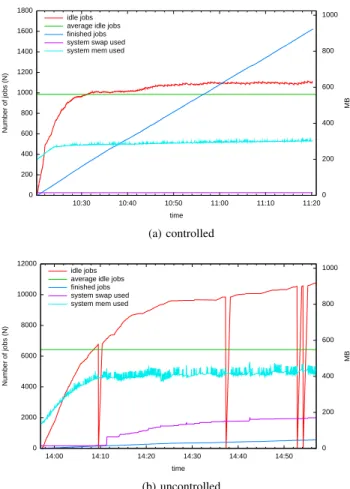
0 200 400 600 800 1000 1200 1400 1600 1800 10:30 10:40 10:50 11:00 11:10 11:20 0 200 400 600 800 1000 Number of jobs (N) MB time idle jobs
average idle jobs finished jobs system swap used system mem used
(a) controlled 0 2000 4000 6000 8000 10000 12000 14:00 14:10 14:20 14:30 14:40 14:50 0 200 400 600 800 1000 Number of jobs (N) MB time idle jobs
average idle jobs finished jobs system swap used system mem used
(b) uncontrolled
Figure 3: System behavior with and without control
together submitting a wide workflow of 1000 tasks each with different running time. We initialized the overload control model with N∗= 1000, Nc= 1500, p = 5, ρ0= 10. Results
are show in figure 3a and figure 3b presenting the system behavior with and without control respectively.
In the feedback controlled system, the amount of idle jobs were for most of the run slightly (6.9%) above the N∗, on average by 69 jobs (116 max). The average load on the host with control was 0.6 in comparison to 3.37 in the system without any control. As shown in figure 3b, major problems arose when the system started running out of memory and started swapping. After that, it spent most of the time waiting for I/O (on average 51.29% of CPU time were iowait comparing to 15.6% in case of the managed system). The gaps in figure 3b were caused by timeouts when condor_q tried to get the queue information from the schedd agent during the period the system was too stressed (corresponding to load > 9).
Finally, one of the important differences is in the amount of work done during the observed period. Because of the resource waste caused by the overload, the unmanaged system executed only 560 tasks while the controlled version did 1620 tasks. This demonstrates the basic capability of the
feedback system generated from our architectural model to regulate the load on this example.
V. RELATEDWORK
In addition to the previous work on architecting loops evoked in Section II, some recent works attempt to propose an explicit fine-grain modelling of feedback control loops. In FORMS [18], the focus is more in characterizing the kinds of autonomic architecture with appropriate metamodels so that they can be compared. Similarly, in [12] Hebig et al. provides an UML profile to explicitly architect several coordinated control loops with component diagrams. Never-theless the loop elements are not adaptive and there is no link to any runtime support.
Regarding control, in [13] Litoiu et al. describe a hierar-chical framework that accommodates scopes and timescales of control actions, and different control algorithms. Their architecture considers three main types of controller reflect-ing the three different stages that they focus on: tunreflect-ing, load balancing and provisioning. While being similar, our architecture is more general but provides less fine-tuned building blocks to control the behavioral models used inside controllers. A lot of research efforts [2], [20], [21] has been put into tackling the problem of overload control of dynamic distributed systems. The major focus has been in designing a scalable and robust adaptive algorithm. In contrast, our main focus is complementary, dealing with the surrounding architecture in order to provide an appropriate supporting environment for the researchers to focus on the adaptation design.
VI. CONCLUSION
In this paper, we have presented an approach to support the architectural design of control loop elements and their connection links. The approach relies on an architectural model that makes control loops and their elements explicit. Moreover each element (sensor, controller, effector, links between them) is uniformly designed as a first-class adaptive element. The proposed model does not help in designing the behavior inside the controllers, but rather in architecting all the surrounding elements. Software architects can thus capture different patterns of interactions and controls (coor-dination of loops, adaptive monitoring, etc.) while reasoning about complex self-adaptive systems. The presented model is also technology agnostic and we provided a default implementation using an OSGi runtime support and a DSL to define architectures from which main parts of the final code are generated.
We also illustrated the architectural model on a overload problem arising in the Condor distributed batch computing system, showing both the capabilities of the model and the efficiency of the resulting code at runtime. The results are obviously only partial and we plan to conduct larger experiments on different and more complex scenarios, both
on Condor and on the gLite grid middleware3. This should enable us to identify some bottlenecks on both the architec-ture and the runtime platform.
Regarding the architectural model, ongoing work consists in turning it into a fully recursive model, so that composition of adaptive elements is supported and larger models can be more easily expressed and managed. Another way to simplify resulting architectures and to improve scalability of the approach is to support inlining of the elements in case there is no direct interaction. Besides, we are currently developing the parts of the runtime support to deal with distribution of the loop elements and making remote links between them self-adaptive.
ACKNOWLEDGMENTS
The authors would like to thank the Condor team from the University of Wisconsin-Madison for all their support, as well as Mireille Blay-Fornarino and the reviewers for valuable comments on the model.
The work reported in this paper is partly funded by the ANR SALTY project4 under contract ANR-09-SEGI-012.
REFERENCES
[1] J. Kephart and D. Chess, “The vision of autonomic computing,” Computer, vol. 36, no. 1, pp. 41–50, Jan. 2004. [2] J. Hellerstein, Y. Diao, S. Parekh, and D. Tilbury, Feedback
control of computing systems. Wiley Online Library, 2004.
[3] B. Cheng, R. de Lemos, H. Giese, P. Inverardi, J. Magee, J. Andersson, B. Becker, N. Bencomo, Y. Brun, B. Cukic, and Others, “Software Engineering for Self-Adaptive Systems: A Research Roadmap,” Software Engineering for Self-Adaptive Systems, pp. 1–26, 2009.
[4] H. M¨uller, M. Pezz`e, and M. Shaw, “Visibility of control in adaptive systems,” Proceedings of the 2nd international workshop on Ultralargescale softwareintensive systems -ULSSIS ’08, pp. 23–26, 2008.
[5] Y. Brun, G. Di Marzo Serugendo, C. Gacek, H. Giese, H. Kienle, M. Litoiu, H. M¨uller, M. Pezz`e, and M. Shaw, “Engineering Self-Adaptive Systems Through Feedback Loops,” Software Engineering for Self-Adaptive Systems, pp. 48–70, 2009.
[6] M. Salehie and L. Tahvildari, “Self-adaptive software: Landscape and research challenges,” ACM Transactions on Autonomous and Adaptive Systems (TAAS), vol. 4, no. 2, pp. 1–42, 2009.
[7] A. Computing, “An Architectural Blueprint for Autonomic Computing, 4. edt,” IBM Autonomic Computing White Paper, vol. 36, 2006.
[8] G. Kaiser, J. Parekh, P. Gross, and G. Valetto, “Kinesthetics eXtreme : An External Infrastructure for Monitoring Dis-tributed Legacy Systems,” in Proceedings of the Autonomic Computing Workshop, 5. International Workshop on Active Middleware Services, Seattle, 2003, pp. 4–13.
3http://glite.cern.ch/ 4https://salty.unice.fr
[9] D. Garlan, B. Schmerl, and P. Steenkiste, “Rainbow: architecture-based self-adaptation with reusable infrastruc-ture,” International Conference on Autonomic Computing, 2004. Proceedings., pp. 276–277, 2004.
[10] H. Liu, M. Parashar, and S. Hariri, “A component based programming framework for autonomic applications,” in Proc. of 1st International Conference on Autonomic
Computing, vol. 9984357, no. 82. Citeseer, 2004, pp.
10–17.
[11] H. Muller, H. Kienle, and U. Stege, “Autonomic Computing Now You See It, Now You Don’t,” Software Engineering, pp. 32–54, 2009.
[12] R. Hebig, H. Giese, and B. Becker, “Making Control Loops Explicit When Architecting Self-Adaptive Systems,”
Proceeding of the Second International Workshop on
Self-Organizing Architectures - SOAR ’10, p. 21, 2010. [13] M. Litoiu, M. Woodside, and T. Zheng, “Hierarchical
Model-Based Autonomic Control of Software Systems,” Proceedings of the 2005 Workshop on Design and Evolution of Autonomic Application Software - DEAS ’05, p. 1, 2005. [14] A. Barker and J. Van Hemert, “Scientific workflow: A
survey and research directions,” in Proceedings of the 7th international conference on Parallel processing and applied
mathematics. Springer-Verlag, 2007, pp. 746–753.
[15] L. Broto, D. Hagimont, E. Annoni, B. Combemale, and J.-P. Bahsoun. Towards a model driven autonomic management system. In Fifth International Conference on Information Technology: New Generations, pages 63–69, 2008.
[16] D. Thain, T. Tannenbaum, and M. Livny, “Distributed computing in practice: The Condor experience,” Concurrency and Computation Practice and Experience, vol. 17, no. 2-4, pp. 323–356, 2005.
[17] OSGi Alliance, “Listeners Considered Harmful : The “Whiteboard ” Pattern,” Technal Whitepaper, 2004. http: //www.osgi.org/wiki/uploads/Links/whiteboard.pdf
[18] D. Weyns, S. Malek, and J. Andersson, “FORMS: a formal reference model for self-adaptation,” in ICAC 2010, 2010, pp. 205–214.
[19] R. Nzekwa, R. Rouvoy, and L. Seinturier, “Modelling Feed-back Control Loops for Self-Adaptive Systems,” Electronic Communications of the EASST Volume 28 (2010), vol. 28, 2010.
[20] N. Bartolini, G. Bongiovanni, and S. Silvestri, “Self-* overload control for distributed web systems,” The IEEE Proceedings of the, no. November 2008, pp. 50–59, Jun. 2008.
[21] S. Parekh, N. Gandhi, J. Hellerstein, D. Tilbury, T. Jayram, and J. Bigus, “Using control theory to achieve service level objectives in performance management,” Real-Time Systems, vol. 23, 2002, pp. 127–141.