HAL Id: hal-02172105
https://hal.archives-ouvertes.fr/hal-02172105v2
Submitted on 2 Oct 2019
HAL is a multi-disciplinary open access
archive for the deposit and dissemination of
sci-entific research documents, whether they are
pub-lished or not. The documents may come from
teaching and research institutions in France or
abroad, or from public or private research centers.
L’archive ouverte pluridisciplinaire HAL, est
destinée au dépôt et à la diffusion de documents
scientifiques de niveau recherche, publiés ou non,
émanant des établissements d’enseignement et de
recherche français ou étrangers, des laboratoires
publics ou privés.
Effects of disc-shaped piezoelectric size reduction on
resonant inductorless DC-DC converter
Benjamin Pollet, Mustapha Touhami, Ghislain Despesse, François Costa
To cite this version:
Benjamin Pollet, Mustapha Touhami, Ghislain Despesse, François Costa. Effects of disc-shaped
piezo-electric size reduction on resonant inductorless DC-DC converter. Transducers/ Eurosensor, Jun 2019,
Berlin, Germany. pp.1423-1426, �10.1109/TRANSDUCERS.2019.8808328�. �hal-02172105v2�
EFFECTS OF DISC-SHAPED PIEZOELECTRIC SIZE REDUCTION ON RESONANT
INDUCTORLESS DC-DC CONVERTER
Benjamin Pollet*
1, 2, Mustapha Touhami
1, 3, Ghislain Despesse
1, 3, François Costa
2, 4, 51
CEA-LETI, Grenoble, France
2SATIE, ENS Paris-Saclay, Cachan, France
3
Minatec Campus, Université Grenoble Alpes, Grenoble, France
4Université Paris-Est, Créteil, France
5
ESPE, Saint-Denis, France
ABSTRACT
This paper studies the impact of disc-shaped piezoelectric resonator dimensions on a non-isolated inductorless piezoelectric DC-DC converter. An analytical model, linking geometrical parameters to output power and efficiency is introduced. This later reveals the benefits of reducing the thickness and diameter of the piezoelectric disk. Five piezoelectric discs with different dimensions are tested and compared in experimental works, giving very high efficiency up to 98 % and output power up to 1.7 W. An exceptional power density of 366 W.cm-3 was measured at 450 kHz for a 25-30 Volt conversion with an efficiency of 81%.
KEYWORDS
Energy conversion, Power electronics, Piezoelectric transducer, DC-DC power conversion
INTRODUCTION
Many power electronics DC-DC converters require a bulky magnetic inductance to store and release energy at each switching period. Piezoelectric-based converters have proved to be a very good alternative for high-gain, low-power converters [1]. For low-power range (until some dozen of Watts) piezoelectric elements have inherent advantages compared to magnetic such as a very high quality factor leading to very high efficiency, a planar shape, a high-power density, low EMI radiations [2] and should be suitable for integration in silicon . The converter described in Figure1 and first presented in [3], [4], has the particularity of using the piezoelectric material as an energy storage element, contrary to most common converters with piezoelectric transformers. It has the advantage of being inductorless, working in zero voltage switching (ZVS) mode (no switching losses) and keeping high efficiency for a very wide range of output ratios and output powers, always driving the system at resonance.
Figure 1: Inductorless DC-DC piezoelectric converter.
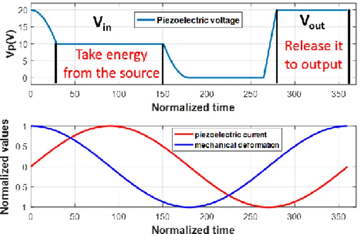
Its principle consists in applying to the piezoelectric transducer the conversion cycle depicted in Figure 2 in which an amount of energy is withdrawn from the input source (Vin), stored temporarily and released to the output
source (Vout). In a steady state, there is, at each cycle, an
energy balance (the taken energy equals the released one), a charge balance and ZVS operations.
Figure 2: steady state step-up conversion cycle.
For a given piezoelectric resonator, very promising efficiencies have been reported [4] but only one piezoelectric resonator was tested. The impact of the material thickness and diameter is only partially mentioned but not fully developed. However, understanding their role is essential to properly design the piezoelectric transducer. This work is based on the analytical model presented in [4] for a step-up converter but the resonator thickness and diameter are added in the model. Five different piezoelectric transducers are tested in experimentation work.
INFLUENCE
OF
PIEZOELECTRIC
DIMENSIONS ON EFFICIENCY AND
OUTPUT POWER
The model presented in [4] is built considering the equivalent circuit of the piezoelectric resonator at resonance that can be seen in Figure 1. R represents the mechanical damping (and its associated losses) but thermal effects and semiconductor losses are neglected. The expression of the efficiency η and maximal output power Pout_max are given in (2) and (3), where ω is the
These expressions give no indications about the geometry of the resonator and the proprieties of the material. That is why the link between the equivalent model of the resonator and the geometry and proprieties of the piezoelectric disc is inserted in the above expression. The relations, taken from [5] using standard notations for piezoelectric coefficients, are used, they are expressed below:
Where th is the thickness, r is the radius, σ is the Poisson ratio, Qm the mechanical quality factor, and ρ is
the material density. These last three equations do not provide very accurate values of the real physical system. However, they give a good representation on how these terms evolve with geometry. For instance, for a given piezoelectric resonator, the value of R will decrease proportionally with thickness. An important point to underlined is that this model presently do not take into account thermal effects and is therefore only relevant when operating far away from the maximal output power (no significant increase in temperature).
The efficiency can now be computed as a function of the piezoelectric disc-shaped resonator dimensions (radius and thickness). Figure 3 represents the theoretical efficiency for a 1W / 10-20V step-up conversion.
Figure 3: Theoretical diameter and thickness influence on the efficiency for a 1W power conversion.
With this model, for a given power, a smaller radius leads to a poorer efficiency for a given output power whereas a smaller thickness improves it. This is logical since the losses are proportional to R. However, the whole converter with all its characteristics must be considered in order to evaluate the global benefit of reducing the size.
Table 1 synthetizes the effects of reducing the piezoelectric resonator size. A higher frequency means a control more difficult to achieve, leading to more switching losses. The maximum current the resonator is able to withstand limits the maximal output power and is directly linked to the electrodes area (and therefore to the diameter). Since the disc is polarized in the thickness direction, reducing the thickness decreases the voltage maximum value.
Table 1: Effect of size reduction on the converter properties Quantity Thickness diminution Diameter diminution Damping (R) - - Frequency = + Maximum power + - Efficiency + - Power density + + Switching losses = + Voltage limit - = Current limit = -
Table 1 highlights the fact that reducing the diameter and thickness have very positive effects until getting close to the material limits. The more restrictive limit is current (measured maximum current amplitude of 650 mA in [4] for D = 25mm and th = 0.75mm) whereas the maximal electric field is around 1600V/mm for C213 Fuji ceramic® resonators. In conclusion, although thickness and radius diminutions both lead to positive effects, it is more advantageous to reduce the thickness compared to the radius considering the limits when operating at low voltage.
EXPERIMENTAL RESULTS
Description of studied piezoelectric disks
The impact of the resonator size is now tested experimentally. Five C213 Fuji ceramic® disc-shaped piezoelectric transducers are tested in radial mode. A picture of these discs is given in Figure 4.
Figure 4: photography of tested piezoelectric resonator
All values of the elements of the equivalent electrical circuit model, including the motional resistance R, are measured using an impedance meter. Table 2 gives the main characteristics of these five discs.
Table 2: Tested piezoelectric resonators Resonator 1 2 3 4 5 D (mm) 25 25 12 12 5 th (mm) 0.75 0.35 0.75 0.35 0.15 R (Ω) 0.4 0.2 0.8 0.5 1.8 C0 (nF) 8.5 15 1.6 3 1.2 Frequency (kHz) 90 90 190 190 450 Q 1280 1080 1190 800 235 kp (%) 58 54 54 53 52
Two pairs of piezoelectric discs have the same diameter but not the same thickness (disks 1-2 and 3-4) and two pairs have the same thickness but a different diameter (disks 1-3 and 2-4). Disc 5 corresponds to the smallest available standard disc-shaped resonator we found. Considering disks 1-2 and 3-4, a lower thickness lead to a drop of the motional resistance R. Contrary to the model of last section, the effective quality factor and coupling factor are not constant whatever the dimensions. Table 2 indicates indeed that they became lower with a drop of radius or thickness.
However, the five R values are higher than the one given by (4). This is caused by the non-perfect fixture of the piezoelectric resonator which damps the resonator. On the one hand, the attachment is not fully punctual and then it induces friction around the contact area (quality factor of the soldering material is very limited compared to the piezoelectric material one). On other hand, the fixture is not perfectly centered on the disc, changing its gravity center and making a moving of the electrical bonding while the piezoelectric material resonate inducing damping. The smaller the disk is, the bigger impact these imperfections have. Since C213 material reports a very high quality factor of 2500, the resonance is therefore limited by the fixture system and not by the material itself. Special care has therefore to be taken for the fixture. In order to reduce the drawback of a soldering bonding, we have chosen to use golden springs contacts with a thin point for the fixture of the piezoelectric resonator.
Comparison of power efficiency curves
The converter is tested with the five disks. Figure 5 represents the measured efficiency vs. power curves for a 10-20V step-up conversion. The reported efficiency do not include the power associated to control.
Figure.5: Comparison of efficiency vs. power curves for a 10-20V step up converter for the 5 discs.
All the efficiency curves, except the one of disk 5, have the same shape that was observed in [4]. First, a section where efficiency increases (because a minimum of energy is necessary to keep the material resonating even though no energy is converted) then at a certain power level, it reaches a maximum of efficiency. Lastly, for higher output powers, the piezoelectric current amplitude
I (and therefore losses) increases, leading the efficiency to
decrease. The same irregularities with a sudden drop of efficiency at some specific output powers, already presented in [4], are observed. Harmonic effects cause them for instance, when the cycle of Figure 2 includes an harmonic content that matches with the resonance frequency of the thickness mode. Very high efficiencies (> 90%) were measured for these 4 disks and for a large range of output powers. However, for disc 5, the maximal efficiency is lower and the range is narrower because of the higher R value.
The maximal output powers (for a given input voltage) are higher for disks 1 and 2 where diameters are the largest. Figure 5 also indicates that for the same radius, the thinner disc lead to higher maximum output power because R is lower. This means that diameter is the most important parameter to maximize output power and should be first considered for design issues. This confirms that the maximal current the material is able to withstand constitutes the limit of the converter. This limit is a thermal one : if the electrode area cannot dissipate losses, the temperature rises and the quality factor decreases [6].
The thickness resonance frequency is higher when thickness lowers. Therefore, the ratio between radial and thickness resonance frequencies increases. The harmonics amplitude of the piezoelectric voltage decreases when moving away from its fundamental (at radial resonance). Therefore, the probability to excite a thickness resonance decreases when the thickness is lower (in the case of 2 disks having the same radii) and so do the number of singularities.
Power density
In this section, the maximal measured power density (per volume and per kg) for an input voltage of 10V is reported for each disk in Table 3. The results correspond to a 10-15 V step-up conversion for disks 1, 2 and 5 and 10-20 V step-up conversion (disk 3 and 4). Disk 5 has the highest measured maximum power density although it has the worst damping.
Table 3: Power density measurements (Vin = 10V)
Resonator 1 2 3 4 5 Maximum output power (mW) 1550 1860 690 731 354 Power density (W.cm-3) 4.21 10.8 8.13 18.5 120 Power per Kilogram (kW.kg-1) 0.54 1.38 1.04 2.37 15.4 Table 3 indicates that smaller sizes lead to higher power densities even if the output power is lower with smaller diameters. It gives very high power densities close to what is reported for classical converters using piezoelectric transformer. For instance, at 100 kHz the maximal reported output power density is less than 35W.cm-3 if no cooling device is added [7], [8] . Besides,
those power conversions were achieved for an input voltage of 10 V. C213 material can withstand an electric field around 1600V.mm-1 which means that we are far
from the applied voltage limit. Higher output powers and therefore higher power densities can therefore be obtained only by increasing the input voltage.
The converter was tested with disk 5 for a 25-30 V step-up conversion (highest voltage we could apply considering the switches we selected). An exceptional power density of 366.7 W.cm-3 (corresponding to 47
kW.kg-1) was converted. The power density has increased
as expected, which means that even higher values could be obtained by having a voltage closer to the material limits. However, the volume and mass of the whole converter (not only the piezoelectric resonator) must be considered.
Figure 6 shows the piezoelectric voltage and current waveforms. Although the current has a rich harmonic content, the cycle of Figure 2 is respected, which means that the converter operates in ZVS mode.
Figure.6: Piezoelectric resonator waveforms at high density of power conversion
CONCLUSION
Reducing the piezoelectric dimensions has several effects on the converter. Theoretically, and in practice, reducing the radius lead to lower output power but to higher power density. Besides, the resonant frequency increases, which makes the control more difficult. Moreover, it increases the risk of seriously damaging the resonance by the fixture of the piezoelectric material. For a given radius, reducing the thickness has globally a very positive effect such as providing higher output power, better power density (for a given input voltage, far from the limit), and decreasing harmonics problems.
Impressive power densities were obtained by increasing the voltage and reducing the radius or thickness.
REFERENCES
[1] R. L. Lin, F. C. Lee, E. M. Baker, and D. Y. Chen, “Inductor-less Piezoelectric Transformer Electronic Ballast for linear fluorescent lamp,” presented at the
APEC, 2001, vol. vol 2, pp. 664–669.
[2] A. Vazquez Carazo, “Piezoelectric Transformers: An Historical Review,” Actuators, vol. 5, no. 2, p. 12, Apr. 2016.
[3] B. Pollet, F. Costa, and G. Despesse, “A new inductorless DC-DC piezoelectric flyback converter,” presented at the ICIT, Lyon, 2018, pp. 585–590.
[4] B. Pollet, G. Despesse, and F. Costa, “A new non-isolated low power inductorless piezoelectric DC-DC converter,” IEEE Trans. Power Electron., pp. 1–1, 2019.
[5] R.-L. Lin, “Piezoelectric transformer characterization and application of electronic ballast,” PhD
Dissertation, Virginia Tech, 2001.
[6] Y. Fuda, K. Kumasaka, M. Katsuno, H. Sato, and Y. Ino, “Piezoelectric Transformer for Cold Cathode Fluorescent Lamp Inverter,” Jpn. J. Appl. Phys., vol. 36, no. Part 1, No. 5B, pp. 3050–3052, May 1997. [7] W. W. Shao, L. J. Chen, C. L. Pan, Y. B. Liu, and Z.
H. Feng, “Power density of piezoelectric transformers improved using a contact heat transfer structure,” IEEE Trans. Ultrason. Ferroelectr. Freq.
Control, vol. 59, no. 1, pp. 73–81, 2012.
[8] Yu-Hao Su, Yuan-Ping Liu, D. Vasic, Wen-Jong Wu, F. Costa, and Chih-Kung Lee, “Power enhancement of piezoelectric transformers by adding heat transfer equipment,” IEEE Trans. Ultrason.
Ferroelectr. Freq. Control, vol. 59, no. 10, pp. 2129–
2136, Oct. 2012.
CONTACT
*B. Pollet; benjamin.pollet@cea.fr