HAL Id: hal-02109537
https://hal-univ-paris8.archives-ouvertes.fr/hal-02109537
Submitted on 6 May 2019HAL is a multi-disciplinary open access archive for the deposit and dissemination of sci-entific research documents, whether they are pub-lished or not. The documents may come from teaching and research institutions in France or abroad, or from public or private research centers.
L’archive ouverte pluridisciplinaire HAL, est destinée au dépôt et à la diffusion de documents scientifiques de niveau recherche, publiés ou non, émanant des établissements d’enseignement et de recherche français ou étrangers, des laboratoires publics ou privés.
Multi-physical Model Simulation and Interoperability
through BIM/ IFC using COMETH Simulation Engine.
Emira El Asmi, Sylvain Robert, Davide Mazza, Khaldoun Zreik
To cite this version:
Emira El Asmi, Sylvain Robert, Davide Mazza, Khaldoun Zreik. Multi-physical Model Simulation and Interoperability through BIM/ IFC using COMETH Simulation Engine.. EuropIA.2014: 14th International conference on the Advances in Design Sciences and Technology, Oct 2014, Nice, France. �hal-02109537�
See discussions, stats, and author profiles for this publication at: https://www.researchgate.net/publication/273106212
Multi-physical Model Simulation and Interoperability through BIM/ IFC using
COMETH Simulation Engine
Conference Paper · October 2014
CITATION
1
READS
221
4 authors, including:
Some of the authors of this publication are also working on these related projects: FUSE-ITView project
HOLISTEEC (FP7 funding, October 2014 - September 2017, https://cordis.europa.eu/project/rcn/109054_en.html))View project Emira El Asmi
Atomic Energy and Alternative Energies Commission 3PUBLICATIONS 16CITATIONS
SEE PROFILE
Sylvain Robert
Atomic Energy and Alternative Energies Commission 30PUBLICATIONS 392CITATIONS
SEE PROFILE
Khaldoun Zreik
Université de Vincennes - Paris 8 97PUBLICATIONS 125CITATIONS
SEE PROFILE
All content following this page was uploaded by Sylvain Robert on 23 September 2015.
Multi-physical Model Simulation and Interoperability through BIM/ IFC
using COMETH Simulation Engine
Emira EL ASMI CEA, LIST, LADIS 91191 Gif-sur-Yvette
CEDEX France [email protected]
Sylvain ROBERT CEA, LIST, LADIS 91191 Gif-sur-Yvette
CEDEX France [email protected]
Davide MAZZA CEA, LIST, LADIS 91191 Gif-sur-Yvette CEDEX France [email protected] Khaldoun ZREIK University Paris 8 URF6, Hypermedia Department Saint-Denis, France [email protected] Abstract
BIM (Building Information Model) applications cover many areas such as quality control, monitoring, structural analysis and space management. BIM is also widely used as a basis for energy simulation as it contains most of the data needed for energy analysis. However, buildings feature multi-physics phenomena in which energy is only one dimension; so there is often a need to perform multi-physical simulation and therefore to properly connect BIM to various simulation environments and formats. In line with this concern, our research work focuses on the issue of multi-models interoperability for simulation. The aim is to devise an approach and to develop some tools that can support and enhance connections between BIM authoring tools and simulation tools covering various physical dimensions. To implement this approach, we propose to rely on some well-proven and focused standards from the Building Smart International consortium, namely the IDM (Information Delivery Manual) and the Model Views Definition (MVD). This paper describes this ongoing work, focusing on its first step – applying the approach to BIM and energy simulation connection. This work is based on the simulation engine COMETH developed in CSTB and implements the IDM process promoted by buildingSMART [1]. The process implied to define a mapping between the building elements as defined in the simulation engine, and the corresponding IFC (Industry Foundation Classes) elements and attributes. As the IFC does not cover all the required elements for energy simulation in COMETH, further enrichment of the IFC – either through ad hoc extension or through connection to complementary is needed.
Keywords
BIM/IFC, interoperability, IDM/MVD, Energy simulation, COMETH.
Introduction
Building information modeling (BIM) is increasingly used in building design activities, especially as a support to energy simulation, where BIM enables for significant time and costs savings. However, energy simulation covers various domains, ranging from acoustic and lighting performance evaluation, to the estimation of the air quality and building ventilation, to the neighboring environment performance. All of these aspects are usually managed separately by different and domain-specific tools, which makes difficult to properly take into consideration the cross-impacts each aspect has on the others.
This paper focuses on the problem of information exchange during the various steps and multidisciplinary simulations used in building conception, dealing in particular with the aspects related to data interoperability among heterogeneous BIM models adopted by the different tools.
The Industry Foundation Classes (IFC) is a standard proposed by buildingSMART and nowadays commonly used as data format for construction projects. It is an object-oriented specification of attributes and relationships between the building entities. Unfortunately, the IFC format does not allow for the full specification of the information needed for energy simulation and to be used by these tools; this issue is still present – even if less - in the latest released version, IFC4. In conjunction with the IFC, on the interoperability side, buildingSMART has developed an approach called Information Delivery Manual (IDM) for the characterization and description of building (design) processes, which goal is especially to define the exchanged information in the processes.
exchange between BIM/CAD tools and simulation tools in order to support and facilitate multi-physical simulations.
This paper focuses on the issue of BIM/IFC and energy simulation connection, with the application of the IDM to the description of the information flow between the IFC and an energy simulation tool compliant with the French thermal regulation (COMETH engine).
This paper is structured as follows: in the first section an overview of BIM interoperability through the standards and processes developed for this purpose is given; the following section outlines the targeted simulation engine (COMETH); in the next one, we outline the related state of the art; and the last section describes the first results of our work, before concluding.
BIM interoperability for simulation IFC, gbXML:
Energy simulation plays an important role in building design by predicting energy performances, in order to support the optimization of design choices throughout the building design process. Regardless of its importance, some problems and challenges still remain when there is the need of data exchange and interoperability between design tools and simulation tools [6].
Data exchange and interoperability is a major issue for the AEC industry, and during the years it has been addressed at first through the definition of standards. This standardization process led to the specification of the most relevant data formats currently used in the AEC industry: IFC and gbXML. A detailed description of IFC and gbXML, and a comparison between them, can be found in [7] and [11].
gbXML (Green Building XML) is a widely-adopted schema for describing data relating to building energy efficiency and its impact on the environment. It allows the description of building geometry and its properties, specifically for energy simulation purposes, thus easing the data exchange between building models and analysis tools. The format presents a well-organized information structure with building data stored through different levels of detail, ranging from campus, building, zone, surface, openings and construction type, and with each of these elements containing information about the composing material parameters. An extract of a gbXML model is shown here after:
<gbXML>
<Campus i d=" c mps - 1" > <Loc at i on>
<Name>Us er Def i ned</ Name> </ Loc at i on>
<Bui l di ng i d=" bl dg- 1" > <Spac e i d=" s p- 101" > <Name>101</ Name> <Ar ea>100</ Ar ea> </ Spac e>
</ Bui l di ng>
<Sur f ac e i d=" s u- s p- 101" s ur f ac eTy pe=" Sl abOnGr ade" > <Adj ac ent Spac eI d s pac eI dRef =" s p - 101" / >
<Rec t angul ar Geomet r y > <Az i mut h>0</ Az i mut h> <Ti l t >180</ Ti l t > <Hei ght >4. 2</ Hei ght > <Wi dt h>10</ Wi dt h> </ Rec t angul ar Geomet r y > </ Sur f ac e>
</ Campus >
<Zone i d=" z one- Def aul t " > <Name>Def aul t </ Name> </ Zone>
</ gbXML>
The format also allows to specify the properties and the features of the neighboring environment, thus enabling to properly take into consideration the context in which the construction is set, beyond the building itself. This is a distinctive feature of this format that has been designed on purpose with the goal of easing the design of green and environment-friendly buildings.
IFC has become the reference standard data format for the building industry. Developed by buildingSmart, it has been kept open and free, and to our knowledge is currently the only format
implemented by most of the CAD tools. It has been specified with the purpose to play that “bridging role” between formats, enabling data exchange and interoperability among tools. Given its object-oriented paradigm, that allows representing all the elements of a building as objects with properties and references to other objects, the IFC format can be easily managed and understood by various tools. An excerpt of a building model in the IFC format is reported thereafter:
. . .
#77=I FCBUI LDI NG( ' 0pz hk p$Qr mi _bXDCUql LWP' , #13, ' ( Cons t r uc t i on) ' , $, $, #74, $, $, . ELE MENT. , $, $, $) ;
#87= I FCCARTESI ANPOI NT( ( 0. , 0. , - 2. 8) ) ; #91= I FCAXI S2PLACEMENT3D( #87, #36, #28) ; #94= I FCLOCALPLACEMENT( #74, #91) ;
#123= I FCMATERI AL( ' Fi br es c i ment ' ) ; #126= I FCDI RECTI ON( ( 6. 1232340E- 17, 1. ) ) ; #1959= I FCPROPERTYSI NGLEVALUE( ' ROOM
NAME' , $, I FCDESCRI PTI VEMEASURE( ' S\ S\ i j our ' ) , $) ;
#1963= I FCPROPERTYSI NGLEVALUE( ' ROOM NUMBER' , $, I FCDESCRI PTI VEMEASURE( ' 01' ) , $) ; #1967= I FCPROPERTYSI NGLEVALUE( ' ROOM LSI ZE' , $, I FCNUMERI CMEASURE( 3. ) , $) ;
. . .
An XML-based version, named ifcXML, has also been proposed, which allows the specification of the same information in the XML format, thus providing and easy and standardized structured data exchange. With respect to the usage in the energy simulation domain, IFC still suffers from some limitations as it does not allow the specifications of all needed elements to express HVAC systems, which represents a big limitation for its use in the energy simulation domain. A currently adopted workaround for this issue is the generation of IFC file from a CAD tool and its enrichment with the thermal and the other energy properties representing the information about HVAC building equipments (we call it “simulation ready architectural file” or Building Simulation Model BSM [13]). This way, the IFC file can then be inputted to a file conversion tool that translates the IFC enriched file into a specific file format for the energy simulation tool to be used.
While being a well-known problem in the AEC industry, the most recent version of IFC has not yet overcome this issue.
IDM/MVD:
During the BIM process, users have the need to exchange partial models designed so far. For this purpose, buildingSmart has proposed a dedicated methodology: the Information Delivery Manual (IDM), which relies on a standard IFC information extraction mechanism called MVD (Model View Definition). These two mechanisms enable to specify how data exchanges between different applications can be done.
The Information Delivery Manual (IDM) specifies when certain types of information are required during the specification of a building project. It offers a common understanding for all the parties involved in the project: when to exchange information and exactly which information is needed. It is composed by:
a Process Map, defining the exchange process;
a set of Exchange Requirements (ERs), defining which information to exchange;
an Exchange Requirements Model (ERM), in order to organize the ERs into exchange concepts;
a generic BIM guide meant as a documentation to the end user.
The Model View Definition (MVD) is a subset of the IFC schema describing the exchange in one or more related IDMs. It contains:
a MVD overview, describing the addressed IDM;
a set of MVD diagrams, defining the MVD concepts to use for the exchange;
a Concept Implementation Guidance, defining the IFC entities to use.
The use of the two methodologies can be better explained through the following figure. During the IDM process, the first step consists in the definition of the actors and their roles; once defined the actors, the specification of their tasks is needed. This will lead to the extraction of the interactions and identification of the set of exchange requirements (ERs). An exchange requirement(ER) describes all details of the requirements to guarantee a successful exchange. Then, the MVD process defines the views extracted from the IFC model that respond to the user’s need.
Figure 1: IDM/MVD Process
The purpose of this work is to integrate the IDM process in order to identify the exchange requirements “energy analysis” using COMETH simulation engine.
Simulation Tools
According to current requirements for BIM, it is necessary to provide the AEC sector with robust and efficient tools capable of communicating with each other by exchanging information and concepts coming from different domains.
In general, an energy simulation tool aims to predict the energy performance of a building with the objective to provide the designer with all the necessary information for a building design that could offer optimal thermal comfort. There are many specialized solutions on the market for simulation tools. [11] provides an indication of the interoperability level among the tools, by specifying the input and output formats of each surveyed tool. It can be easily noticed that the most common used formats are IFC and gbXML.
The required input data of simulation tools for energy analysis are usually the following: building structure (geometry, spaces/thermal zones, building orientation, building construction, building usage), HVAC system requirements (heating, lighting, ventilating and air conditioning system) [11]; weather data and other simulation engine-specific parameters, such as the period of the simulation, have to be added. Output results generally include the building thermal performance, and an overall estimation of energy use and related monetary cost.
Figure 2: Input/output data of thermal simulation engines COMETH
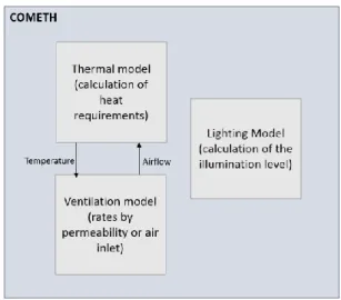
This work makes use of COMETH, a simulation engine developed at CSTB since 2009. COMETH stands for COre for Modelling Energy and Thermal Comfort. It allows to calculate heat demand, to specify a ventilation model, a lighting model and the management of the openings / fenestrations of the building.
As a result, it computes the building’s energy consumption at an hourly time step. In order to allow for collaborative developments to enable co-simulation, a COMETH-related ontology has been developed [2].
Input data for the energy simulation always need to be particularly accurate; provided information mainly consists in the building geometry and orientation, HVAC systems, project location (weather data) and simulation parameters. And the typical outputs for the simulation are energy/thermal analysis, lighting analysis, acoustic, cost analysis [8].
COMETH is composed three main models: thermal, ventilation and lighting model (see figure 3). The models include the description of the HVAC equipment deployed in the building.
Figure 3: COMETH models
COMETH models are divided into different elements: building elements, distribution elements, lighting, exterior, emission system, heat system, photovoltaic system and ventilation (see below).
COMETH System decomposition Building elements Distribution elements Lighting
Exterior environment Emission system Heat generation system PV system
Ventilation system Table 1: COMETH elements Related Work
Effective building project management requires information exchange among all the concerned stakeholders; it is also a multidisciplinary task that has to consider contributions and expertise of different practitioners. The AECOO-1 (Architects, Engineers, Construction, Owners & Operators) Testbed [12] deals with the conceptual design phase of the building design process and has developed the IDM for the energy analysis, by then defined the subsets of IFC classes needed for these analysis. It deals with data exchange between BIM tools and the EnergyPlus energy analysis software. A similar approach has been used in this work in order to establish the IDM process applied to COMETH by extracting the different involved IFC elements.
With respect to the mapping of ER components into IFC elements, the recently-ended PLUMES project is worth being mentioned here. This project developed a unified software platform for building energy efficiency optimization which aim is to extend the IFC objects and properties for the representation of the equipment of the energy systems of a building [15]. The targeted simulation engines are EnergyPlus, Trnsys and Modelica. As results of the project, a set of additional property is proposed for an inclusion into future versions of IFC.
The problems of interoperability between models, as targeted by this work, are also the main limitation to the adoption of BIM for multi-physics simulations [10]. The work in [9] proposes a solution to this problem through the development of system interfaces between BIM, multi-domain simulations (such as solar, thermal) and daylighting simulations. The aim is to enhance interoperability between design models
and energy models by improving the exchange between thermal and daylighting models. They use the BIM authoring tool Autodesk Revit and its API on the modeling side, and Modelica and its building library for thermal modeling and Radiance/DAYSIM for daylighting modeling on the simulation side. Preliminary results – connection of IFC and COMETH by means of IDM and MVD
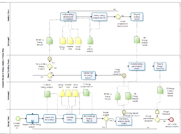
IDM is composed of four main deliverables: 1) a document defining the process participants, information and format to be exchanged and for what purpose, 2) the process map using BPMN templates describing the business processes through a graphical notation, 3) the exchange requirements document including all the exchanged information identified in the process map, and 4) a series of entity relationships diagrams ERM developed for each high level object in the information exchange.
The following figure is the process map for energy analysis. In this process map we can distinguish three involved actors: the design team, the client and the analysis team. At the beginning we have a concept design BIM, this BIM will be prepared and exported for energy analysis. At this step we will focus on the exchange requirement from design to energy analysis “ER BIM to Energy Analysis”. This exchange requirement will be passed on to the analysis team in order to evaluate the energy performance results.
Figure 4: The Process Map In the following, we will structure our work in different steps: 1. Establishment of ER tables for simulation with COMETH
2. Extraction of IFC elements and properties needed to describe the HVAC system
3. Detection of missing data that are required for simulation and enrichment of IFC with the proposition of property sets
1) Required HVAC SYSTEMs and IDM/ ER Table according to HVAC simulation:
We will first present the HVAC system components needed for simulation, then extract the IFC correspondent elements and propose some possible enhancements.
Our target environment is COMETH, which describes a ventilation system, a heat generation system, lighting and photovoltaic system. The following table enumerates some of the components of each system.
COMETH System Components
generation (heat) system boiler, cooling tower, pumps ventilation system fans
distribution elements pumps
photovoltaic system photovoltaic panel
lighting system …
Table 2: HVAC components
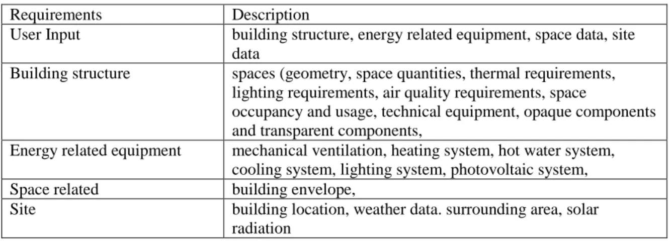
The ER “BIM to Energy Analysis” contains the geometry; it aims to prepare BIM to energy analysis and simulation. It will also contain the energy related materiel, location and climate data. The following table enumerates the elements needed for exchange.
Requirements Description
User Input building structure, energy related equipment, space data, site data
Building structure spaces (geometry, space quantities, thermal requirements, lighting requirements, air quality requirements, space
occupancy and usage, technical equipment, opaque components and transparent components,
Energy related equipment mechanical ventilation, heating system, hot water system, cooling system, lighting system, photovoltaic system,
Space related building envelope,
Site building location, weather data. surrounding area, solar radiation
Table 3: Exchange requirements BIM to energy analysis The exchange requirements are organized as follows:
Building structure elements, describing the building geometry: building spaces, thermal bridges, space occupancy, opaque elements (wall), transparent elements (door, window)
Building HVAC related requirements: thermal requirements (heating, cooling), lighting requirements, aeration requirements, natural ventilation requirements
HVAC equipment: mechanical ventilation, heating system, hot water system, lighting system, photovoltaic system,
Site and exterior environment: building location, weather data.
2) Mapping from ER to IFC/ Extraction of IFC elements and properties needed to describe the HVAC system:
In this section, we will draw the ER table detailing all components used in COMETH to perform the energy simulation and their mapping with the correspondent IFC object classes and their properties (Pset).
In the following table we tried to summarize the IFC elements representing different HVAC
systems/components. We identified the IFC elements that should best fit each elements/system. The IFC version used is IFC4.
Category Element Correspondent IFC elements/ property set B ui ld ing G eo m et ry
Building elements IfcBuilding, IfcBuilding.name + Pset_BuildingCommon Spaces, occupancy IfcBuilding
+ Pset_BuildingCommon, occupancyType IfcSpace
+Pset_SpaceOccupancyRequirements, occupancyType Building opaque
components
IfcWall, IfcSlab, IfcRoof, IfcColumn, IfcBeam, IfcRamp, IfcStair
Building transparent components
IfcOpeningElement
Eg. IfcDoor, IfcWindow, IfcCurtainXall
H V A C R equi re m en ts Thermal requirements IfcBuilding + Pset_SpaceThermalRequirements,AirConditioning Lighting requirements IfcBuilding + Pset_SpaceLightingRequirements, Illuminance + Pset_SpaceLightingRequirements, ArtificialLignting Natural Ventilation requirements
IfcSpace, IfcSpatialZone, IfcZone, IfcSpaceType + Pset_SpaceThermalRequirements, NaturalVentilation IfcDistributionSystem + Pset_DistributionSystemTypeVentilation H V A C Syst em co m pone nt s Mechanical ventilation system IfcDistributionSystem.PredefinedType = VENTILATION IfcFan, IfcFanType + Pset_FanTypeCommon Hot water system
(Boiler) IfcBoiler, IfcBoilerType + Pset_BoilerTypeCommon IfcDistributionSystem.PredefinedType=DOMESTICHOTWATER IfcPump IfcCoolingTower, IfcCoolingTowerType Lighting system IfcBuilding
+ Pset_SpaceLigntingRequirements, Illuminance Photovoltaic system IfcSolarDevice
Table 4: Exchange requirements with IFC mapping 3) Extension of IFC/ enrichment of IFC, proposition of property sets:
While IFC 4 is more extensive than the previous version, it still features limitation regarding energy elements description. In the following table we draw some of the properties needed in COMETH and that IFC 4 do not cover.
Elements to add
Mechanical ventilation system Maximum Flow Rate
Coefficient of singular loss Hot water system
(boiler, pump, coolingTower)
Nature of the boiler to determine the default loss coefficient
Thermostat Management type of the boiler
Electric power of cooling towers
Maximum allowed temperature (resp. minimal) of air in the output/upstream source in cooling mode
Water temperature at the output of the tower
Pump's power loss
Lighting system Control mode of lighting
Total power of equipment and handling devices of artificial lighting in the room
Photovoltaic system, Solar sensor PV solar inverter efficiency curve
Temperature coefficient of the peak power
Number of sensors Table 5: Possible extension to IFC
Taking as an example the boiler, we can notice that even there are improvements in IFC4 compared to IFC3; it is still not expressive enough to describe boiler properties. We need to complete the list of property set by adding new one following our needs (or to make a reference to a complementary external model). For example (see table below), we can propose a property set in order to know the coefficient of thermal loss.
Components Unit Type IFC elements and properties
Function int
Hot water production characteristics
String
Max temperature °C double IfcBoiler + IfcPropertySingleValue (Pset_BoilerTypeCommon,
OutletTemperatureRange) Nature of the ball to determine the
loss coefficient default
String
Thermostat Management type of the boiler
int
Coefficient of thermal loss W/K double
Total volume L double IfcBoiler + IfcPropertySingleValue
(Pset_BoilerTypeCommon, WaterStorageCapacity) Table 6 : ER table (eg. The boiler)
The solution is either to add new property set to the IFC or to propose new elements for the IFC model to be added in the next version. This latter solution has many drawbacks: in fact, adding new elements in the model requires the development of new concepts, attributes and relations and this will take a considerable time. Also, the standard will contain much information becoming more complex. An alternative solution consists in the extension of the BIM model thanks to existing mechanisms in the data model such as user property sets. Actually, IfcPropertySet can be attached to any kind of elements with a key-value and thus enable the extension of their attributes. They are a special capability in the IFC Model allowing the extension of the model without affecting it (no change). This solution offers more flexibility. It is simple and fast to implement and does not imply changes on the model.
Discussion
IFC is meant, among other things, to act as a bridge format enabling the exchange of information between design tools and simulation tools. However, the data model features some limitations that hinder its effectiveness. In order to overcome its limitations, one possible solution is its enrichment using standard mechanisms (property sets). In our case, we focused on the IFC enrichment for HVAC system description with COMETH simulation engine. We followed the IDM process to structure this work in order to better define the needed elements and to draw the exchange requirements. As a result, we obtained a subset of the IFC model representing a simulation view. Further enhancements are still needed in order to generate an IFC file ready for energy simulation, that we call the Building Simulation Model (BSM).
We plan to benefit from the work performed in an ongoing European research project called HOLISTEEC, which is aimed at designing, developing, and demonstrating a BIM-based, collaborative building design software platform, featuring advanced design support for multi-criteria building optimization [12]. COMETH is the targeted simulation tool and one of the main assets of the project is a multi-physical simulation engine covering acoustics, environmental evaluation and lighting on top of energy.
simulation, in order to decouple the energy simulation information from the actual energy simulation tool adopted. The abstraction provided by BSM will allow then to map the modeled concepts to a specific simulation engine input formats, such as COMETH or EnergyPlus, through a model-to-model transformation task.
An alternative, in order not to impact the IFC itself through the use of property sets, would be to store these additional parameters in an external file, and then to make a reference to it in the IFC – multi-modeling approaches [15] are clearly a sound basis to implement such approaches. In this context we can resort to the link model approach [14] based on a separated model which acts as a bridge between the BIM model and the external data source. This model contains a set of link objects related to the relationships between different interdependent models; each link object is referenced with a number of model elements from these elementary models through their identifiers.
Conclusion
Implementation of BIM-based solution for simulation has grown in the last years. This increasing BIM usage in this field led to a multitude of propositions for tools capable of multi-physical simulation. This work showed that the current version IFC4 still present limitations for a proper energy simulation which lead us to add some enhancements to the IFC model by adding ‘user property sets’ in order to express HVAC elements needed to do simulation.
In this work, we got a view of the IFC model describing the exchange requirements from design phase to energy analysis. Further step on this side would be the deepening of the interpretation of simulation results and their injection through the same procedure to complete the model.
On the modeling side, a future step would be represented by the specification of a BSM allowing the mapping of IFC building description with various simulation environments and the exploration of multi-modeling approaches.
From the point of view of the considered physical models, we would like to apply the approach proposed in this paper to other physical simulations, such as the acoustic one.
Acknowledgements
This PhD work is performed in CEA LIST labs, and co-funded by CSTB. The work presented in this paper is done in collaboration with CSTB using the simulation engine COMETH, developed by CSTB. References
[1] BuildingSMART. 2014. http://www.buildingsmart.org/
[2] Haas B., Corrales P., 2014. Solution pour l’interopérabilité avec COMETH, Conférence IBPSA,
France Arras.
[3] Cormier A., Hilaire B., 2011. Plumes: Spécifications IFC/systèmes énergétiques, Technical report [4] Open Geospatial Consortium Inc., buildingSMART alliance. 2008. AECOO-1 Testbed Information
Delivery Manual (IDM) for Building Performance and Energy Analysis (BPEA) Thread, bSa Project
report.
[5] Ahn K. U., Kim Y. J., Park C. S., Kim I., Lee K., 2014. BIM interface for full vs. semi-automated building energy simulation, Energy and Buildings: 671–678.
[6] Motawa I., Carter, K., 2013. Sustainable BIM-based Evaluation of Buildings, Procedia - Social and
Behavioral Sciences 74: 419-428.
[7] Dong B., Lam K.P., Huang Y.C., and Dobbs G.M., 2007. A comparative study of the IFC and gbXML informational infrastructures for data exchange in computational design support environments,
Building Simulation: 1530-1537.
[8] Male T., Fischer M., Bazjanac V., 2007. Building Energy Performance Simulation Tools: A Lifecycle and interoperable perspective, Center for Integrated Facility Engineering (CIFE) Working
Paper 107.
[9] Yan W., Clayton M., Haberl J., Jeong W. S., Kim J. B., 2013. Interfacing BIM with Building Thermal and Daylighting Modeling, 13th International Conference of the International Building Performance Simulation Association (IBPSA): 25-28. Chambery, France.
energy use and cooling equipment size using a multi-objective optimization scheme, Energy and
Buildings 43: 2055-2067.
[11] Bahar Y.N., Pere C., Landrieu J., Nicolle C. A., 2013. A Thermal Simulation Tool for Building and Its Interoperability through the Building Information Modeling (BIM) Platform, Buildings: 380-398. [12] HOLISTEEC Project deliverable. FP7 2013. Holistic and Optimized Life-cycle Integrated Support
for Energy-Efficient building design and Construction. http://www.holisteecproject.eu/.
[13] Robert S., Hilaire B., Sette P., Soubra S., 2012. Paving the way for exhaustive and seamless BIM-Based building enery simulation, proceedings of CIB W078 conference, Beirut, Lebanon.
[14] Liebich T, Katranushlov P., Weise M., and Guruz R., 2013. Extending BIM for multi-model domain tasks. In ICT for Sustainable Places Conference.
[15] Scherer R. J., Schapke S. E., 2011. A distributed multi-model-based management information system for simulation and decision-making on construction projects. Advanced Engineering
Informatics, 25(4):582 – 599. Special Section: Advances and Challenges in Computing in Civil and
Building Engineering.
View publication stats View publication stats