HAL Id: cea-02509783
https://hal-cea.archives-ouvertes.fr/cea-02509783
Submitted on 17 Mar 2020
HAL is a multi-disciplinary open access
archive for the deposit and dissemination of
sci-entific research documents, whether they are
pub-lished or not. The documents may come from
teaching and research institutions in France or
abroad, or from public or private research centers.
L’archive ouverte pluridisciplinaire HAL, est
destinée au dépôt et à la diffusion de documents
scientifiques de niveau recherche, publiés ou non,
émanant des établissements d’enseignement et de
recherche français ou étrangers, des laboratoires
publics ou privés.
Digital in-line holography for near field observation of
liquid-liquid flows under astigmatic conditions
F. Lamadie, M. Sentis, Laurent Bruel
To cite this version:
F. Lamadie, M. Sentis, Laurent Bruel. Digital in-line holography for near field observation of
liquid-liquid flows under astigmatic conditions. LIP 2016 - The 11th International Conference on laser-light
and Interactions with Particles, Apr 2016, Xi’an, China. �cea-02509783�
D
IGITAL IN-
LINE HOLOGRAPHYF
ORN
EARF
IELDO
BSERVATIONO
FL
IQUID-L
IQUIDF
LOWS UNDER ASTIGMATIC CONDITIONSMatthias PL SENTIS 1, Fabrice LAMADIE 1*, Laurent BRUEL 2
1 CEA, DEN, DTEC, SGCS, F-30207 Bagnols-sur-Cèze, France 2 CEA, DEN, DTEC, SEPE, F-30207 Bagnols-sur-Cèze, France
*Corresponding author: fabrice.lamadie@cea.fr
Abstract
Several processes used in nuclear research and industry are based on liquid-liquid extraction. This method is designed for selective separation of products in a mixture.
As the transfer occurs at the contact surface between both phases, the characterization of the dispersed phase of the emulsion (size distribution of droplets, shape, etc.) is fundamental. Numerous imaging techniques can be used to measure, but one of them, digital holography (DH) is particularly relevant as it determines simultaneously the size, shape and 3D positions of particles using a single camera. Because the droplets are millimeter size, a near-field diffraction regime is observed and adapted numerical solutions are required. In a previous work [1], an effective focusing method has been validated on an experimental cuboid-shape setup designed to produce droplets of known diameter and velocity as well as an unknown polydisperse droplet population. However, the standard shapes of liquid-liquid extraction apparatus are cylindrical, inducing a strong astigmatism and preventing the direct use of classical focusing methods.
In this communication, we proposed a survey of two approaches, based respectively on Generalized Huygens-Fresnel Transform (GHFT) and Fractional Fourier Transform (FrFT), which allows overpassing this issue. Using these tools induce a supplementary quadratic phase term, which must be corrected in order to use automatic focalisation methods.
1 Introduction
Digital Holography (DH), is well-known for allowing complete reconstruction of information about a 3D Flow in a single shot. Accordingly, DH has been increasingly used in a broad spectrum of applications, such as holographic PIV/PTV [2–4], live cell imaging [5] or holographic microscopy [6]. More recently DH has been directly applied to a dispersed phase for the characterization of particle motion in a two-phase flow [7]. Finally it has been demonstrated that DH can be used for measuring size and 3D positioning of fast-moving droplets and bubbles in air-water and oil-air-water mixture flows [8].
As proved by Lamadie et al. [1], DH involves a very simple and stable measurement setup particularly suitable for the characterization of liquid-liquid flows. Feasibility of such measurements in cuboid-shape geometry has been demonstrated [1]. However, several standard devices
designed for chemical engineering (for instance pulsed columns, centrifugal extractor, etc.) exhibit a cylindrical shaft inducing astigmatism. Due to this latter, the classical hologram simulation and focusing methods become inadequate.
Two main approaches allow taking into account this astigmatism. The first one, introduced by Collins et al. in 1970 [9] is a general expression of the Rayleigh-Sommerfeld integral, including optical system in paraxial approximation thanks to an ABCD transfer matrix. It gives the relationship between the output and input of the complex amplitude distributions of the light field passing through an ABCD optical system. In this context, Rayleigh-Sommerfeld diffraction integral could be analytically expressed, as proved by Verrier et al. [11] or used through a generalised Huygens-Fresnel propagator as described by Palma et al. [12]. The second one, introduced by Ozaktas et
al. [10], operates the Fractional Fourier Transform (FrFT)
properties. According to [10], all quadratic phase systems (QPS) can be interpreted as a magnified FrFT with a phase curvature.
In this communication, we propose a comparison of the two approaches on numerical and experimental astigmatic holograms. The first paragraph is dedicated to hologram’s numerical simulation, both with GHFT and FrFT. Regarding automatic focalisation, a key issue is the quadratic phase correction, it will be introduced in the second paragraph. Finally some experimental results will be presented.
2 Hologram simulation in anamorphic optical system
In DH, several focusing methods involve a numerical model for hologram’s simulation. In free space, this point
is easily achieved by using Fresnel Transfer Function or Impulse Response Propagator [13]. Switch between the two propagators is related to sampling of the phase of the propagator at the edge of the field. As mentioned in the introduction, in the paraxial approximation, all optical systems can be described by an ABCD matrix. For a DH setup, regarding one particle, we have to consider two propagations along the optical axis 𝑧𝑧, one between the light source and the particle (represented by transfer matrices
ABCD
1x and ABCD1 y ) and one between theLASER-LIGHT AND INTERACTIONS WITH PARTICLES APRIL 22-26TH,2016,XI’AN,CHINA
2 x
ABCD
and ABCD2 y), allowing to consider differentoptical characteristics along the x and y axes.
According to the Collins formula, the wave amplitude
z
A
after propagating in such system [9, 12] is describedby:
(
)
( )
2( )
2 2 2 2 exp 2 , , exp 2 exp x x z x x y y y y ikz A u xu D x A x y A u v i B i B B A v yv D y i dudv B π λ λ π λ − + = − + × ∫∫
(1) with 𝐴𝐴(𝑢𝑢, 𝑣𝑣) the complex amplitude distributions of the light field in the z-particle position,A B C D
x,
x,
x,
x and, , ,
y y y y
A B C D the coefficients of the ABCD transfer matrix in x and y direction respectively.
λ
is the wavelength, 𝑧𝑧 the distance of propagation along the optical axis and 𝑘𝑘 the wave number.Considering the classical transmission model used in DH, which assimilates a droplet to an opaque disk (hypothesis acceptable for micrometric particles but not for millimeter particles [1]), the simulation of the recorded intensity is performed by three simple operations:
(i) propagation of the incident wave from the source to the particle plane using equation (1) and
1
x x
ABCD
=
ABCD
,ABCD
y=
ABCD
1y matrices,(ii) multiplication of the calculated field, at z-particle position, by the particle transmission function,
(iii) propagation of the resulting field from the particle plane to the sensor position using equation (1) and
2
x x
ABCD
=
ABCD
, ABCDy =ABCD2y matrices.As demonstrated, by Verrier et al., 𝐴𝐴(𝑢𝑢, 𝑣𝑣) can be calculated thanks to an analytical solution by considering an incident gaussian beam profile and a gaussian decomposition of the opaque particle [11]. The
Figure 1(a) shows the intensity recording by a sensor calculated with this analytical solution for an experimental setup with a cylindrical curvature along the x-axis detailed in [1].
According to Palma et al., GHFT integral can be expressed as a Fourier transformation. In this case, Eq.1 can be rewritten as :
( )
(
)
(
)
(
( )
)
( )
(
)
2 2 1 2 2 , exp exp , , y x z x y x y x x x y y y C C i i A x y x y A A F A A i A B f A B f F A u v x y π π λ λ πλ − = + × − + (2) with fx =x(
λA Bx x)
,fy=y(
λA By y)
the spatialfrequencies along x and y respectively.
Required sampling conditions, regarding Shannon theorem, bring sampling issues that can be addressed by considering a general system taking into account the two initial ABCD systems. A comparison between Verrier approach and GHFT approach is presented in Figure 1.
The results are very close regarding the intensity profile comparison in Figure 1(c). Finally, as demonstrated by Ozaktas et al. [10], all QPS can be interpreted as a magnified FrFT with a phase curvature. This third approach has been applied successfully for free space propagation and still under study for ABCD systems.
-0,008 -0,006 -0,004 -0,002 0,000 0,002 0,004 0,006 0,008 0,0 2,0x10⁻⁴ 4,0x10⁻⁴ 6,0x10⁻⁴ 8,0x10⁻⁴ 1,0x10⁻³ 1,2x10⁻³ 1,4x10⁻³ In te n sity p ro file , I(x ,y = 0 ) [mm] x [mm] Analytical solution GHFT
Figure 1: Intensity recorded for a 1mm diameter TPH
droplets in water (experimental setup described in [1]) - Analytical solution (a) - GHFT (b) and (c) Intensity profile
comparison
3 Hologram focusing
Positioning on the optical axis (z-axis) is certainly one of the most critical aspects of DH. The challenge is to find the optimum focus plane for each particle detected in the hologram. Various automatic detection criteria have been reported in the literature, while some authors prefer empirical methods based on visual analysis of the reconstructed holograms. In cuboid-shape configuration, the most accurate positioning is obtained using exclusively the imaginary part of the reconstructed field. For instance, the position of the particle could be determined by using the minimum of the variance of the imaginary part of the reconstructed field in the neighbourhood of the particle [14].
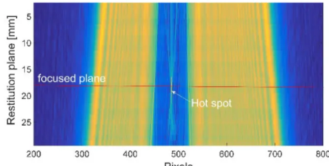
Coëtmellec has proved that hologram restitution in anamorphic optical system can be successfully performed with FrFT [15]. As an example, the Figure 2 shows a cross section of modulus of the reconstructed field of an experimental hologram with FrFT at several propagation distances. For each reconstruction plane, fractional orders are calculated according to Verrier [11] which allows to reduce the computation time. The expected refraction effect for particles with refractive index higher than one,
(a) (b)
LASER-LIGHT AND INTERACTIONS WITH PARTICLES APRIL 22-26TH,2016,XI’AN,CHINA
i.e. a “hot spot” close to the particle center position, is
clearly observed (Figure 2).
Figure 2 : Cross section of modulus of the field reconstructed
with FrFT (the section plane passes through the center of the droplet and contains the z axis)
An example of the imaginary part of the reconstructed field with FrFT is displayed in Figure 3(a). The figure exhibits additional quadratic phase inherent to FrFT. The variance induced by this quadratic phase is far more significantly than the variance induced by the phase of the droplet, preventing the use of the focus function. Figure 3(b) shows the imaginary part of the reconstructed field with FrFT after quadratic phase corrections. The variance induced by the quadratic phase has totally disappeared and focalisation, thanks to a merit function, remains available as proved in Figure 4. This process is validated for isolated droplet hologram and under study for polydisperse droplets distributions.
Figure 3: Imaginary part of the focused field by FrFT at z =
40mm with (a) supplementary FrFT phase (b) phase correction
0 5 10 15 20 25 30 6,80x10⁻⁴ 6,90x10⁻⁴ 7,00x10⁻⁴ 7,10x10⁻⁴ 7,20x10⁻⁴ 7,30x10⁻⁴ 7,40x10⁻⁴ 7,50x10⁻⁴ A ut of oc us f unc ti on [ u.a ] Restitution distance, z [mm] F oc us ed pl ane
Figure 4: Autofocus function of the imaginary part of the
reconstructed field versus the reconstruction distance z —the local minimum indicates the focus position
4 References
[1] Lamadie, F., L. Bruel and M. Himbert (2012). "Digital holographic measurement of liquid–liquid two-phase flows." Optics and Lasers in Engineering 50(12): 1716-1725.
[2] Pan, G., and Meng, H., 2003. “Digital holography of particle fields: reconstruction by use of complex amplitude”. Appl. Opt., 42, pp. 827– 833.
[3] Malek, M., Allano, D., Coe¨tmellec, S., O¨ zkul, S., and Lebrun, D., 2004. “Digital in-line holography for three dimensional, two-component particle tracking velocimetry”. Meas. Sci. Technol., 15, p. 699.
[4] Hinsch, K., 2002. “Holographic particle image velocimetry”. Meas. Sci. Technol., 13(7), Jul, pp. R61–R72.
[5] Choi, Y.-S., and Lee, S.-J., 2009. “Three-dimensional volumetric measurement of red blood cell motion using digital holographic microscopy”. Appl. Opt., 48(16), pp. 2983 – 2990.
[6] Dubois, F., Schockaert, C., Callens, N., and Yourassowsky, C., 2006. “Focus plane detection criteria in digital holography microscopy by amplitude analysis”. Opt. Express, 14(13), Jun, pp. 5895–5908. [7] Salah, N., Godard, G., Lebrun, D., Paranthoën, P., Allano, D., and Coëtmellec, S., 2008. “Application of multiple exposure digital in-line holography to particle tracking in a bénard-von kármán vortex flow”. Meas. Sci. Technol., 19(7), p. 074001.
[8] Tian, L., N. Loomis, Domínguez-Caballero, J. A., and Barbastathis, G., 2010. “Quantitative measurement of size and three-dimensional position of fast-moving bubbles in air water mixture flows using digital holography”. Appl. Opt., 49(9), Mar, pp. 1549–1554.
[9] Collins, J. and A. Stuart (1970). "Lens-system diffraction integral written in terms of matrix optics." JOSA 60(9): 1168-1177.
[10] Ozaktas, H. M., Z. Zalevsky and M. A. Kutay (2001). The fractional Fourier transform, Wiley, Chichester.
[11] Verrier, N., Coëtmellec, S., Brunel, M., & Lebrun, D. (2008). Digital in-line holography in thick optical systems: application to visualization in pipes. Applied optics, 47(22), 4147-4157.
[12] Palma, C. and V. Bagini (1997). "Extension of the Fresnel transform to ABCD systems." JOSA A 14(8): 1774-1779.
[13] Voelz, D., 2011. Computational Fourier Optics. SPIE Press. [14] Lamadie, F. and L. Bruel (2014). "Processing method for near-field in-line holograms (Fresnel number ≥ 1)." Optics and Lasers in Engineering 57: 130-137.
[15] Coëtmellec, S., W. Wichitwong, G. Gréhan, D. Lebrun, M. Brunel and A. Janssen (2014). "Digital in-line holography assessment for general phase and opaque particle." Journal of the European Optical Society-Rapid publications 9.