HAL Id: in2p3-00520762
http://hal.in2p3.fr/in2p3-00520762
Submitted on 24 Sep 2010
HAL is a multi-disciplinary open access
archive for the deposit and dissemination of
sci-entific research documents, whether they are
pub-lished or not. The documents may come from
teaching and research institutions in France or
abroad, or from public or private research centers.
L’archive ouverte pluridisciplinaire HAL, est
destinée au dépôt et à la diffusion de documents
scientifiques de niveau recherche, publiés ou non,
émanant des établissements d’enseignement et de
recherche français ou étrangers, des laboratoires
publics ou privés.
Survey and alignment concept for the SPIRAL2
accelerator (status report)
R. Beunard, A. Lefèvre, F. Legruel
To cite this version:
R. Beunard, A. Lefèvre, F. Legruel. Survey and alignment concept for the SPIRAL2 accelerator (status
report). 11th International Workshop on Accelerator Alignment (IWAA2010), Sep 2010, Hamburg,
Germany. pp.1-5. �in2p3-00520762�
SPIRAL2 ACCELERATOR (STATUS REPORT)
Rémy BEUNARD, Alexis LEFEVRE, François LEGRUEL, GANIL*, Caen, France
Michel FONTAINE, IRFU, Saclay, France
Abstract
The SPIRAL2** project located at the GANIL facility (Caen, France) has been studied since the beginning of 2003, and is now under construction. This project aims at delivering rare (radioactive) isotope beams with intensities not yet available with presently running machines. An important aspect of this project is that it is foreseen to deliver up to five different beams in parallel to the users.
This paper is a status report on the survey and alignment techniques selected for installation of the SPIRAL2 accelerator devices [1].
INTRODUCTION
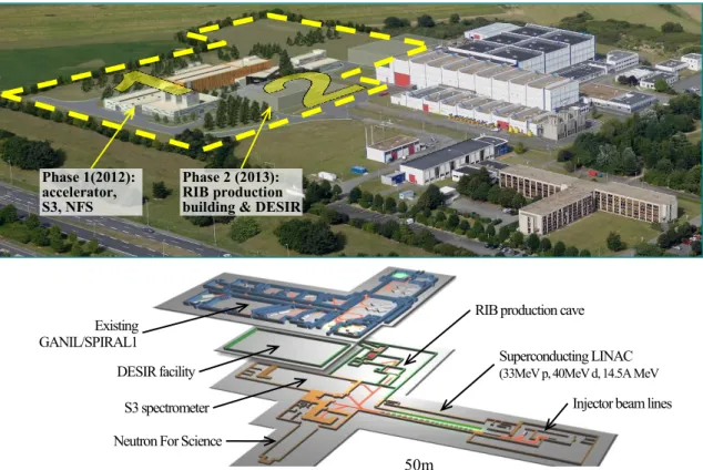
SPIRAL2 is the project of a facility intended for the production of new beams of stable and radioactive ions at GANIL. The SPIRAL2 facility (see Fig.1) is based on a high-power superconducting driver LINAC which delivers a high-intensity, 40-MeV deuteron beam, as well
as a variety of heavy-ion beams with mass-to-charge ratio equal to 3 and energy up to 14.5 MeV/u. The driver accelerator will send stable beams to new experimental areas (phase 1) and to a cave (phase 2) for the production of Radioactive Ion Beams (RIB). The commissioning of the driver should start in 2012 at GANIL.
Fast neutrons produced from the break-up of the 5 mA deuteron beam using a carbon converter will induce up to 1014 fissions/s in a uranium carbide target. The extracted RIB will subsequently be accelerated to energies up to 20 MeV/u (typically 6 7 MeV/u for fission fragments) by the existing CIME cyclotron.
The surveying and alignment activities at GANIL are under the responsibility of a three people team in the Techniques of Physic Department. The surveyor team supports and interacts with physicists and engineers working on any specific projects, from the detailed design study, to the final alignment of components on the beam line. Phase 1(2012): accelerator, S3, NFS Phase 2 (2013): RIB production building & DESIR
Figure 1: Layouts of the SPIRAL2 project and existing GANIL facility
Existing GANIL/SPIRAL1
DESIR facility S3 spectrometer Neutron For Science
RIB production cave Superconducting LINAC
(33MeV p, 40MeV d, 14.5A MeV HI)
Injector beam lines
50m
___________________________________________________________
*GANIL: Grand Accélérateur National d’Ions Lourds [Large-scale national accelerator for heavy ions]
**SPIRAL2 : Système de Production d’Ions Radioactifs Accélérés en Ligne [production system of on-line accelerated radioactive ions]
THE RADIO FREQUENCY
QUADRUPOLE (RFQ)
RFQ fiducialization
The localization of the RFQ requires fiducial points transferred on the top of the vacuum vessel by adjustable plates equipped with a conical centering-surface for a Taylor-Hobson-Sphere (see Fig. 2). These spheres are the only reference points which will be accessible. Their spatial coordinates will be given in the reference system of the object.
Figure 2: Model of the RFQ
Network for metrological control of the vanes
and the fiducial points
The network measurement will be made with a laser tracker. The reference network (see Fig. 3) will consist of approximately 6 pillars (green), 6 floor monuments (blue) and 4 laser tracker stations. Two sets of angles and 8 interferometer distances will be observed from each tracker station to all fiducials points (see Fig.4). The estimated global error is 60 μm (RMS at 2σ).
Figure 3: Measurements to be made on RFQ modules
Figure 4: a RFQ module and its fiducial points
THE MEDIUM ENERGY
BEAM LINE (LME)
The medium energy beam line (LME) is the line located just before the LINAC. It consists of different components including three rebunchers.
An alignment plate was designed to align these rebunchers. This plate will have two goals:
initial alignment
monitoring the position of the component throughout the lifetime of the accelerator
Figure 5: Initial alignment (on the left) and monitoring the displacement (on the right)
For the initial alignment, the plate will be used upside down (see Fig. 5, on the left). Then, for monitoring, the plate will be set up in the second position (see Fig. 5, on the right).
This alignment plate includes three characteristics (see Fig. 6):
an optical target mount (1.5”) a tilt meter base
a 10 mm bore to insert a reflector holder
THE SUPERCONDUCTING LINAC
The solution adopted to support the Linac components, is a welded-frame structure equipped with guide rails (see Fig. 7).
One advantage of this solution is the possibility of bringing a component into a laboratory together with its support in order to do, for example, a realignment of the cavities inside the cryostat then to put it back on the beam line under the same conditions, using the guide rails [2].
Figure 7: View of the LINAC
Alignment concept component fiducialisation
As the components cannot be aligned through the beam tube, the solution adopted is to transfer, on a bench, new parallel axis outside the objects, i.e. to one side of their supports by means of adjustable target boxes – fiducials (see Fig. 8 to 11).
Two benches were made ; they are an exact replica of the welded-frame structure for the LINAC.
The three-dimensional coordinates of the fiducials are measured in the reference system of the accelerating tubes for the cavities and the mechanical axis of the poles for the magnets. A portable measuring arm is used to measure the fiducials (volumetric accuracy given by this system is ± 0.06 mm at 2σ).
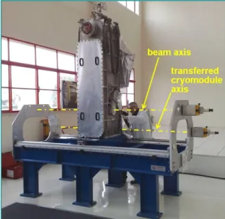
Figure 8: Cryomodule B on the bench for axis transfer operation
Figure 9: Cryomodule B on the bench for axis transfer operation (view from above)
Figure 10: View of a warm section on its support equipped with fiducials
Figure 11: Cryomodule A on the bench for axis transfer operation
The tolerated maximum static errors for the global alignment of LINAC components are:
Transfer methodology of the cavities beam axis
for cryomodules A
During assembly process, once the cavity is clean, its beam tube is closed and it cannot be accessed outside a clean room.
Consequently, an axis transfer tool (see Fig. 12) has been designed. It is set up around the cavity on highly accurate mechanical holder. Once the tool is set up, the cryomodule and cavity can be aligned on the bench and then the fiducials can be adjusted parallel to the beam axis [3].
Figure 12: Axis transfer tool set up on a A-cavity
Transfer methodology of the cavities beam axis
for cryomodules B
Constraints on accessing the beam tube are the same as for the cryomodule A.
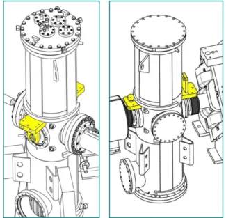
The choice was made on equipping the cavities with adjustable target mounts that will remain permanently (see Fig. 13).
The transfer was carried out by means of an inter-dependent tool introduced into the beam tubes. Then, the target mounts could be precisely adjusted parallel to the beam axis [4].
The adjustment was performed with an error on the transferred axis position of 0.1mm approximately.
Figure 13: adjustable target mounts
Qualifying cryomodule B: measurement of the
cavities displacements during vacuum and
cooling down tests
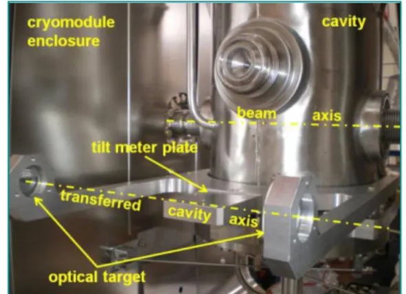
The cryomodules are equipped with optical targets on the transferred cavity axis in order to sight the cavity targets under vacuum and supra conditions. The purpose is to be able to adjust and correct cavity alignment in working conditions i.e. at 4°K (see Fig. 14).
Figure 14: sketch of cavity alignment in working conditions
A measurement campaign was conducted to observe cavities displacement during vacuum and cooling down tests [5]. Measurements were observed in two stages because stability to 4°K is obtained only after 2 to 3 days. The first campaign concerns the impact due to the vacuum and the second due to the cooling down. The technical principles include an optical method by using a Taylor Hobson micro alignment telescope. The measurements are shown graphically on the next page (see Fig. 16).
Specific targets have been designed (see Fig 15) because optical ones did not pass the first vacuum and cooling down tests (@20°K): silver drawings of circles disappeared.
Figure 15: Target comprising crossed gold tungsten threads
cavities quadrupoles
displacement ± 1.0 mm ± 0.1 mm
rotation (X, Y) ± 0.3 deg ± 0.03 deg
Figure 16: Results of the measurement campaign (references 2 to 5 are related with the sketch of figure 14)
ACKNOWLEDGEMENT
I would like to acknowledge all members of the GANIL design offices, as well as the colleagues from the other laboratories involved in this project, particularly from IPN ORSAY and the IRFU SACLAY.
REFERENCES
[1] R. Beunard, Survey and alignment concept for installation of the SPIRAL2 accelerator devices at GANIL, Proceedings of the 10th International Workshop on Accelerator Alignment, KEK, Tsukuba, 2008.
[2] R. Beunard, The alignment strategy for the SPIRAL2 superconducting cryomodules, Proceedings of the 10th International Workshop on Accelerator Alignment, KEK,2008.
[3] R. Beunard, Test cryomodule A: transfer of the cavity beam axis, internal note, EDMS n° 010375, March.2007 [4] R. Beunard, Test cryomodule B: transfer of the cavity beam axis, internal note, EDMS n° 011823, Nov.2007. [5] R. Beunard & A. Lefèvre, Test2: qualifying cryomodule B, displacements during vacuum and cooling down, internal note, EDMS n° 016352, March 2009.