A Coupled Contact-Mechanics Computational Model
for Studying Deformable Human-Artifact Contact
by
Christopher David King
Submitted to the Department of Mechanical Engineering
in partial fulfillment of the requirements for the degree of
Master of Science in Mechanical Engineering
at the
MASSACHUSETTS INSTITUTE OF TECHNOLOGY
June 2018
c
○
Massachusetts Institute of Technology 2018. All rights reserved.
Author . . . .
Department of Mechanical Engineering
May 23, 2018
Certified by. . . .
Leia Stirling
Assistant Professor
Charles Stark Draper Professor of Aeronautics and Astronautics
Thesis Supervisor
Certified by. . . .
Raúl Radovitzky
Professor
Certified by. . . .
Kenneth Kamrin
Thesis Reader, Associate Professor
Accepted by . . . .
Rohan Abeyaratne
Chairman, Department Committee on Graduate Theses
A Coupled Contact-Mechanics Computational Model for
Studying Deformable Human-Artifact Contact
by
Christopher David King
Submitted to the Department of Mechanical Engineering on May 23, 2018, in partial fulfillment of the
requirements for the degree of
Master of Science in Mechanical Engineering
Abstract
Gas-pressurized spacesuits are necessary for human spaceflight, most notably for ex-travehicular activity (EVA). Legacy EVA suits have been primarily rigid, and opera-tion in such suits can result in significant metabolic expense, or even injury, for the wearer. To reduce these effects, modern spacesuits are more flexible, through the incorporation of more softgood materials and specially designed joint interfaces such as hip bearings. However, modeling the effects of human-suit interaction for these softgood materials is challenging due to the highly deformable nature of the suit cou-pled with the deformable nature of the human. To enable improved analysis and design of modern spacesuits, a computational model that can resolve the structural deformations of the suit and human resulting from contact interactions is developed. This thesis details the development and validation of a coupled contact-mechanics solver architecture for use in studying the effects of human-artifact interaction, par-ticularly with respect to pressurized softgood exosuit design. To resolve contact and structural mechanics interactions for a deformable human and artifact, a finite ele-ment model is developed. First, the SUMMIT computational framework is employed for resolving the structural deformations of the system, and is coupled to an ex-plicit contact mechanics scheme. The exex-plicit contact scheme is implemented so as to resolve both external- and self-contact problems. Next, the model architecture is integrated to enable parallelization of both the structural deformation and contact systems, and computational scaling investigated. A computational trade study is performed to benchmark the coupled contact-mechanics method against a simpler rigid body model employing a penalty method. Following this, the model is validated against experimental data for various artifact contact problems. The explicit coupled contact-mechanics model is found to effectively capture contact interactions of the experimental data, with improved fidelity for deformable contact interactions. With careful tuning of the system properties, the coupled contact-mechanics model enables an architecture for an integrated human-suit analysis and design model.
Thesis Supervisor: Leia Stirling Title: Assistant Professor
Acknowledgments
I want to thank Leia Stirling for giving me the opportunity to work on this project, and join the Man Vehicle Lab at MIT. I’m incredibly thankful that she chose to reach out to me when I started graduate study at MIT, as this work has not only been exciting and challenging, but her guidance, knowledge, and patience as an advisor is incredible. Even when I was in the weeds of reviving legacy code, or stretched too thin due to deadlines at my job, she was always understanding and able to parse the problems into realizable increments to keep the project on track and help me balance conflicts. I’d also like to thank Conor, Aditi, Patrick and Alvin, from the MVL who worked on this NRI project for all the help, especially in experimental methods, and all the fun car rides out to DCCI.
I also want to thank Raúl Radovitzky for allowing me to work alongside his re-search team in the ISN using the computational framework SUMMIT, which formed the primary basis for the model. His knowledge of computational structural mechan-ics, Euler-Lagrangian mechanmechan-ics, contact methods, and parallel computation schemes are unparalleled, and the model could not have been successful without his guidance. Even though I was not an official member of his research team, he allowed me to be an active member of the software development team, and was always available to help me with any problem, whether as high-level as modeling philosophy, or as low-level as repository management. The rigorous software development methods he instilled in me over the course of this project have been beneficial to me in both school and my career, and I am incredibly thankful for his continued efforts to help me grow. I’d also like to thank the members of the RRGroup which have helped me along the way, especially Ryadh, Biana, Anwar, Mohammad, Brian and Tom, who have helped me sort out either particularly tricky bugs, or my particularly tricky self-made mistakes. I’d also like to apologize to them for remoting into Nimble at any given hour and lighting up the entire lab without warning. I also want to thank my in-department reader, Ken Kamrin, for agreeing to read my thesis for the Mechanical Engineering department.
I’d also like to thank Paul Lopiccolo, Tom Martyn, and Paul Patoulidis for not only allowing me the flexibility to work on my thesis and travel to MIT concurrent with my work obligations during the work week, but for going far above and beyond in helping me with GE thesis procedures. This work has given me experience in project and software development, along with extensive computational modeling methods that will continue to help me throughout my career.
My parents and sister deserve special thanks for always being in my corner and picking up the phone at any random hour to talk, and for helping me balance work and life when I felt overwhelmed. I also want to thank Jessie for going through this whole experience with me, both at MIT and at work, for being an incredible friend, and for helping me stay (mostly) sane. Finally, I want to thank my wife, Kaitlin, for giving me the courage to pursue graduate study at MIT, and for supporting me through all the long nights and crazy schedules. I couldn’t have done it without you.
Contents
1 Introduction 23
1.1 Motivation . . . 23
1.2 Objective . . . 24
1.3 Overall Model Connectivity and Architecture . . . 26
1.4 Human-Artifact Contact Models . . . 30
1.4.1 Multi-Body Surrogate Models . . . 31
1.4.2 Finite Element Method Models . . . 32
1.4.3 Particle-Based Models . . . 33
1.5 Relevance to Musculoskeletal Forward Dynamics . . . 36
1.6 Overview of Thesis . . . 37
2 Methodology 39 2.1 Model Architecture Selection . . . 40
2.2 Structural Mechanics Framework and Model . . . 42
2.3 Constitutive Material Models . . . 42
2.4 Contact Mechanics Model . . . 44
2.4.1 Pedigree of Contact Enforcement Methods . . . 46
2.4.2 Explicit Decomposition Contact Response Method . . . 48
2.5 Coupled Contact-Mechanics Architecture . . . 55
2.5.1 Explicit Integration Scheme . . . 55
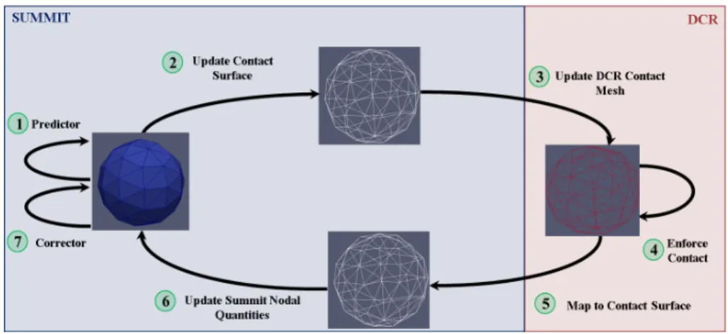
2.5.2 Contact-Mechanics PEC Formulation . . . 57
2.6 Software Architecture and Communication for Serial Computation . . 58
2.7.1 Serial Computational Complexity Studies . . . 64
2.7.2 Partitioning and Load Balancing Approaches . . . 67
2.7.3 Parallel Scaling Capability . . . 73
2.8 Trade Comparison against Simplified Rigid-Body Approaches . . . 77
3 Experimental Validation 93 3.1 Overview of Contact Regimes of Interest . . . 94
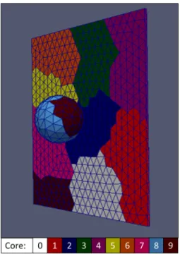
3.2 Experimental Validation Testing . . . 95
3.2.1 Contact Benchtop Rig Design . . . 96
3.2.2 Experimental Test Plan and Setup . . . 101
3.3 Contact Model Validation Study . . . 102
3.3.1 Model Representation of Experimental Rig . . . 103
3.3.2 Model Meshing and Boundary Condition Setup . . . 106
3.3.3 Model Post-Processing Procedure . . . 112
3.4 Comparison of Model to Experimental Results . . . 115
3.4.1 Rigid Impactor, Fixed Artifact Configuration Results . . . 116
3.4.2 Rigid Impactor, Free Artifact Configuration Results . . . 123
3.4.3 Flexible Impactor, Fixed Artifact Configuration Results . . . . 127
3.4.4 Flexible Impactor, Free Artifact Configuration Results . . . . 130
3.5 Summary of Results . . . 134
4 Conclusions and Future Work 137 4.1 Coupled Contact-Mechanics Model Capability . . . 137
4.2 Future Work . . . 141
4.2.1 CCM-Musculoskeletal Model Pipeline Development . . . 141
4.2.2 Integrated Minimum Stable Time Step . . . 142
4.2.3 Contact Surface Parallelization Improvements . . . 145
4.2.4 Large Deformation Contact Problems . . . 146
A SUMMIT::ContactSurface Detailed Code Description and
Documen-tation 149
B Trade Study Relative Error to Runtime Cost Results 167
C Experimental Benchtop Rig Test Case Results 177
D Universal I-DEAS to SUMMIT Connectivity Toolset 191
List of Figures
1-1 NASA Mark III EVA Suit [1] (left) and DCCI Demonstrator LEA Suit [2] (right) . . . 25 1-2 DCCI Demonstrator Suit Knee Region experiencing Self-Contact [2] . 26 1-3 High-Level, Preliminary Integrated Human-Suit Model Architecture . 27 1-4 High-Level Integrated Human-Suit Model Architecture with selected
component methods and calibration inputs . . . 29 1-5 Illustration of Multi-Body Surrogate Contact Models for Dynamic
Mus-culoskeletal Models as employed in SimTK [3] (left) and Todorov:2014 [4] (right) . . . 32 1-6 Illustration of FEM Human-Artifact Contact Problem resolving
pres-sure distributions across a donned cotton shirt using Mindlin-Reissner Shell elements, per Wang et. al. [5] . . . 34 1-7 Illustration of Particle-based method as adapted from the work of
Volino and Magnenat-Thallman [6], representing anisotropic bending stiffness in a flexible cloth garment, while capturing the rest posture curvature of the garment in self-contact . . . 34 2-1 Contact Penalty Method Force Formulation . . . 46 2-2 Explicit DCR Lumped Mass Vertex Momentum Conservation Concept
- Node at position 𝑥 at time 𝑡𝑖−1crosses the contact boundary Γ at time
𝑡𝑖, and is pushed back by contact enforcement to a corrected position
˜
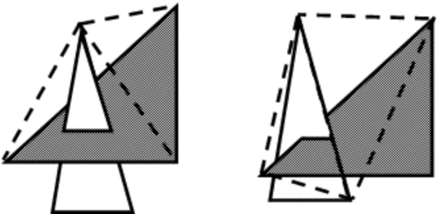
2-3 Considered Finite Element Contact Types and Resultant Intersection Tetrahedrons for DCR Method are node-face intersection (left) and edge-edge intersection (right) . . . 52 2-4 SUMMIT-Based Contact Surface Data Structure and I/O Connectivity
- SUMMIT base code (pink), DCR base code (blue), Contact Surface developed code (purple), where bold blocks are classes, italicized blocks are functions, and blocks with gradient fills are parallel functions . . . 60 2-5 Coupled Contact-Mechanics Data Flow Representation in Serial
Com-putation . . . 61 2-6 Example of Back-to-Back Software Cycle Comparison for Debug and
Optimized Contact-Mechanics Model Code, Total Function Cycle Counts [top] versus Self-Cycle Counts [bottom], where SUM is a SUMMIT do-main code, CS is a ContactSurface dodo-main code, and DCR is a DCR domain code . . . 62 2-7 Simple Sphere-Plate Contact Problem for Serial Computational Cost
Analysis . . . 64 2-8 Transient Simulation Response for Serial Scaling Test Case, Coarse Mesh 65 2-9 Computational Cost Scaling with Element Count in Serial Computation 66 2-10 Structural Mechanics Domain Partitioning by Equal Element Load
Balancing . . . 69 2-11 Contact DCR Domain Partitioning by Zoltan RCB Dynamic Partitioning 71 212 ContactMechanics PEC Algorithm Procedure in Parallel with MPI
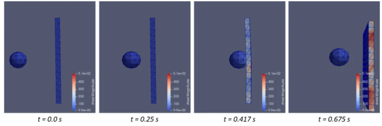
-relative to the Serial Procedure, step 3 is new and step 6 is modified to enable MPI gathering across the partitions . . . 72 2-13 Hollow Sphere, Plate Contact Problem for Parallel Scaling Study . . 74
2-14 Parallel Scaling Study Results for Contact-Mechanics Model Compo-nents, with Contact Mechanics Iteration Time using Equal-Elements (EE) Static Partitioning [blue], Contact Mechanics Iteration Time us-ing Recursive Coordinate Bisectionus-ing (RCB) Dynamic Partitionus-ing [orange], and Structural Mechanics Iteration Time using Equal-Elements
(EE) Static Partitioning [grey] . . . 75
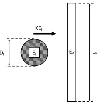
2-15 Trade Study Model with Primary Variable Degrees of Freedom . . . . 78
2-16 Total Computational Runtime for Trade Study Cases . . . 80
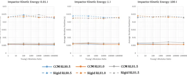
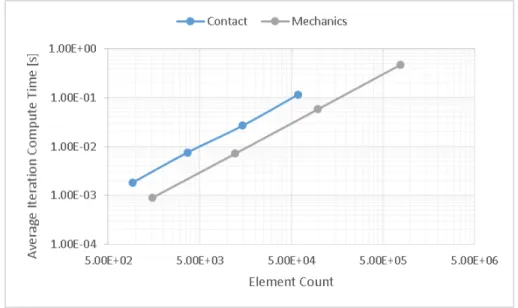
2-17 Average Iteration Computation Time for Trade Study Cases . . . 81
2-18 Initial Minimum Stable Time Step for Trade Study Cases . . . 82
2-19 Comparison of CCM and Rigid Body Model Transient Results for Ar-tifact Average Kinetic Energy with 𝑡𝑐= 0.1 𝑠 . . . 82
2-20 Comparison of 𝐸𝑅 : 106, 𝑅𝐿𝑆 : 0.5, 𝐾𝐸 : 100[︀𝐽]︀ Deformation . . . 83
2-21 Comparison of 𝑝𝑖𝐸𝑅 : 100, 𝑅𝐿𝑆 : 0.5, 𝐾𝐸 : 100[︀𝐽]︀ Deformation . . 84
2-22 Normalized Error in Average Displacement for All Cases . . . 86
2-23 Normalized Error in Max Displacement for All Cases . . . 86
2-24 Normalized Error in Average Kinetic Energy for All Cases . . . 87
2-25 Normalized Error in Average Displacement at 𝑡𝑓 𝑖𝑛𝑎𝑙 for All Cases . . . 88
2-26 Normalized Error in Max Displacement at 𝑡𝑓 𝑖𝑛𝑎𝑙 for All Cases . . . 88
2-27 Normalized Error in Average Kinetic Energy at 𝑡𝑓 𝑖𝑛𝑎𝑙 for All Cases . . 89
2-28 Normalized Runtime, 𝑁𝑇 , for CCM and Rigid Body Models versus 𝐸𝑅, 𝑅𝐿𝑆, and Impactor 𝐾𝐸, with 𝑁𝑇𝐶𝐶𝑀 surface fit (blue) and data (blue dots), and 𝑁𝑇𝑅𝑖𝑔𝑖𝑑 surface fit (red) and data (red dots) . . . 91
2-29 Weighted error-to-cost metric: Relative error in average artifact kinetic energy at the end of simulation per Runtime Ratio results, with surface fit (blue surface) and simulation data (blue dots) . . . 92
3-1 Experimental Validation Test Concept . . . 96
3-2 Impactor Design for Experimental Benchtop Rig . . . 97
3-4 Artifact Design for Experimental Benchtop Rig, with internal "skele-ton" aluminum joint with stabilizers [left], and with external PVC
exterior for contact testing [right] . . . 98
3-5 Artifact Pin Joint for Enabling Restricted or Free Rotational Motion 99 3-6 Vicon Pearl Placement for 𝑉𝐼 Measurement on Impactor . . . 99
3-7 Novel Pliance Sensor Placement for 𝑃 on Artifact . . . 100
3-8 Vicon Pearl Placement for 𝜃𝐴 Measurement on Artifact . . . 100
3-9 Experimental Benchtop Rig with weight attached to Impactor Assembly102 3-10 Full Artifact Assembly CAD Model . . . 103
3-11 Rotational-Only Artifact CAD - High Fidelity (left), Simplified (right) 104 3-12 Impactor CAD Model - Rigid Configuration . . . 104
3-13 Impactor CAD Model - Flexible Configuration (left), 𝐾𝑠 check (right) 105 3-14 Combined CAD Model with Initial Geometry . . . 106
3-15 Rigid Impactor, Fixed Artifact Simplicial Mesh . . . 107
3-16 Impactor Input Force Boundary Condition Location . . . 107
3-17 Selected Surfaces for Contact Enforcement . . . 108
3-18 Dirichlet Constraints Applied to Impactor . . . 109
3-19 Nodal locations for Dirichlet constraints applied to artifact to enforce Fixed/Free configurations . . . 110
3-20 Nodes used for 𝑉𝑖 tracking in CCM Model Simulation Results . . . . 112
3-21 Node used for 𝜃𝑎 tracking in CCM Model Simulation Results . . . 113
3-22 Normalized Bode Diagram of Digital 1st-Order Lowpass Filter applied to CCM model simulation pressure results for alignment with experi-mental pressure data sampling rate . . . 115
3-23 RX025 𝑉𝑖 Transient Results, Experimental (blue), CCM Model (grey dashed), Experimental Contact Time (blue dotted), CCM Contact Time (grey dotted) . . . 117
3-24 RX025 𝜃𝑎 Transient Results, Experimental (blue), CCM Model (grey dashed), Experimental Contact Time (blue dash), CCM Contact Time (grey dotted) . . . 119
3-25 RX025 𝑃 Transient Results, Experimental (blue), CCM Model (grey dashed), Experimental Contact Time (blue dash), CCM Contact Time (grey dotted) . . . 120 3-26 RX025 𝑉𝑖 Transient Results, Experimental (blue), CCM Model with
Frictional Constraint (orange), CCM Model with Exact Constraint (grey dashed), Experimental Contact Time (blue dotted), CCM with Frictional Constraint Contact Time (orange dotted), CCM with Exact Constraint Contact Time (grey dotted) . . . 121 3-27 RX025 𝜃𝑎 Transient Results, Experimental (blue), CCM Model with
Frictional Constraint (orange), CCM Model with Exact Constraint (grey dashed), Experimental Contact Time (blue dotted), CCM with Frictional Constraint Contact Time (orange dotted), CCM with Exact Constraint Contact Time (grey dotted) . . . 122 3-28 RX025 𝑃 Transient Results, Experimental (blue), CCM Model with
Frictional Constraint (orange), CCM Model with Exact Constraint (grey dashed), Experimental Contact Time (blue dotted), CCM with Frictional Constraint Contact Time (orange dotted), CCM with Exact Constraint Contact Time (grey dotted) . . . 123 3-29 RF025 𝑉𝑖 Transient Results, Experimental (blue), CCM Model with
friction (orange), CCM Model with no friction (grey dashed), Exper-imental Contact Time (blue dash), CCM Contact Time with artifact friction (orange dotted), CCM Contact Time with no artifact friction (grey dotted) . . . 124 3-30 RF025 𝜃𝑎 Transient Results, Experimental (blue), CCM Model with
artifact friction (orange), CCM Model with no artifact friction (grey dashed), Experimental Contact Time (blue dash), CCM Contact Time with artifact friction (orange dotted), CCM Contact Time with no artifact friction (grey dotted) . . . 125
3-31 RF025 𝑃 Transient Results, Experimental (blue), CCM Model with artifact friction (orange), CCM Model without artifact friction (grey dashed), Experimental Contact Time (blue dash), CCM Contact Time with artifact friction (orange dotted), CCM Contact Time without artifact friction (grey dotted) . . . 126 3-32 FX025 𝑉𝑖 Transient Results, Experimental (blue), CCM Model (grey
dashed), Experimental Contact Time (blue dash), CCM Contact Time (grey dotted) . . . 128 3-33 FX025 𝜃𝑎 Transient Results, Experimental (blue), CCM Model (grey
dashed), Experimental Contact Time (blue dash), CCM Contact Time (grey dotted) . . . 129 3-34 FX025 𝑃 Transient Results, Experimental (blue), CCM Model (grey
dashed), Experimental Contact Time (blue dash), CCM Contact Time (grey dotted) . . . 130 3-35 FF025 𝑉𝑖 Transient Results, Experimental (blue), CCM Model with
artifact friction (orange), CCM Model without artifact friction (grey dashed), Experimental Contact Time (blue dash), CCM Contact Time with artifact friction (orange dotted), CCM Contact Time without artifact friction (grey dotted) . . . 131 3-36 FF025 𝜃𝑎 Transient Results, Experimental (blue), CCM Model with
artifact friction (orange), CCM Model without artifact friction (grey dashed), Experimental Contact Time (blue dash), CCM Contact Time with artifact friction (orange dotted), CCM Contact Time without artifact friction (grey dotted) . . . 132 3-37 FF025 𝑃 Transient Results, Experimental (blue), CCM Model with
artifact friction (orange), CCM Model without artifact friction (grey dashed), Experimental Contact Time (blue dash), CCM Contact Time with artifact friction (orange dotted), CCM Contact Time without artifact friction (grey dotted) . . . 133
4-1 Overlay of RX025/RF025 contact domain (green dot), FX025/FF025 contact domain (yellow dot), and approximated human-suit interaction domain (purple surface), on the weighting function of average artifact kinetic energy error per runtime ratio (blue surface), with trade study simulation data (blue dots) . . . 140 B-1 Error-Cost Weighting Function: Relative error in average displacement
at simulation end per Runtime Ratio expense, with surface fit (blue) and simulation data (blue dots) and surface equation expressed below for an impactor with 10 J kinetic energy . . . 168 B-2 Error-Cost Weighting Function: Relative error in average displacement
at simulation end per Runtime Ratio expense, with surface fit (blue) and simulation data (blue dots) and surface equation expressed below for an impactor with 50 J kinetic energy . . . 169 B-3 Error-Cost Weighting Function: Relative error in average displacement
at simulation end per Runtime Ratio expense, with surface fit (blue) and simulation data (blue dots) and surface equation expressed below for an impactor with 100 J kinetic energy . . . 170 B-4 Error-Cost Weighting Function: Relative error in maximum
displace-ment at simulation end per Runtime Ratio expense, with surface fit (blue) and simulation data (blue dots) and surface equation expressed below for an impactor with 10 J kinetic energy . . . 171 B-5 Error-Cost Weighting Function: Relative error in maximum
displace-ment at simulation end per Runtime Ratio expense, with surface fit (blue) and simulation data (blue dots) and surface equation expressed below for an impactor with 50 J kinetic energy . . . 172 B-6 Error-Cost Weighting Function: Relative error in maximum
displace-ment at simulation end per Runtime Ratio expense, with surface fit (blue) and simulation data (blue dots) and surface equation expressed below for an impactor with 100 J kinetic energy . . . 173
B-7 Error-Cost Weighting Function: Relative error in average artifact ki-netic energy at simulation end per Runtime Ratio expense, with sur-face fit (blue) and simulation data (blue dots) and sursur-face equation
expressed below for an impactor with 10 J kinetic energy . . . 174
B-8 Error-Cost Weighting Function: Relative error in average artifact ki-netic energy at simulation end per Runtime Ratio expense, with sur-face fit (blue) and simulation data (blue dots) and sursur-face equation expressed below for an impactor with 50 J kinetic energy . . . 175
B-9 Error-Cost Weighting Function: Relative error in average artifact ki-netic energy at simulation end per Runtime Ratio expense, with sur-face fit (blue) and simulation data (blue dots) and sursur-face equation expressed below for an impactor with 100 J kinetic energy . . . 176
C-1 Rigid Impactor, Fixed Artifact, 0.25 m/s - Artifact Angle . . . 178
C-2 Rigid Impactor, Fixed Artifact, 0.25 m/s - Impactor Velocity . . . 178
C-3 Rigid Impactor, Fixed Artifact, 0.25 m/s - Impact Pressure . . . 179
C-4 Rigid Impactor, Fixed Artifact, 0.50 m/s - Artifact Angle . . . 179
C-5 Rigid Impactor, Fixed Artifact, 0.50 m/s - Impactor Velocity . . . 179
C-6 Rigid Impactor, Fixed Artifact, 0.50 m/s - Impact Pressure . . . 180
C-7 Rigid Impactor, Fixed Artifact, 1.00 m/s - Artifact Angle . . . 180
C-8 Rigid Impactor, Fixed Artifact, 1.00 m/s - Impactor Velocity . . . 180
C-9 Rigid Impactor, Fixed Artifact, 1.00 m/s - Impact Pressure . . . 181
C-10 Rigid Impactor, Free Artifact, 0.25 m/s - Artifact Angle . . . 181
C-11 Rigid Impactor, Free Artifact, 0.25 m/s - Impactor Velocity . . . 181
C-12 Rigid Impactor, Free Artifact, 0.25 m/s - Impact Pressure . . . 182
C-13 Rigid Impactor, Free Artifact, 0.50 m/s - Artifact Angle . . . 182
C-14 Rigid Impactor, Free Artifact, 0.50 m/s - Impactor Velocity . . . 182
C-15 Rigid Impactor, Free Artifact, 0.50 m/s - Impact Pressure . . . 183
C-16 Rigid Impactor, Free Artifact, 1.00 m/s - Artifact Angle . . . 183
C-18 Rigid Impactor, Free Artifact, 1.00 m/s - Impact Pressure . . . 184 C-19 Flexible Impactor, Fixed Artifact, 0.25 m/s - Artifact Angle . . . 184 C-20 Flexible Impactor, Fixed Artifact, 0.25 m/s - Impactor Velocity . . . 184 C-21 Flexible Impactor, Fixed Artifact, 0.25 m/s - Impact Pressure . . . . 185 C-22 Flexible Impactor, Fixed Artifact, 0.50 m/s - Artifact Angle . . . 185 C-23 Flexible Impactor, Fixed Artifact, 0.50 m/s - Impactor Velocity . . . 185 C-24 Flexible Impactor, Fixed Artifact, 0.50 m/s - Impact Pressure . . . . 186 C-25 Flexible Impactor, Fixed Artifact, 1.00 m/s - Artifact Angle . . . 186 C-26 Flexible Impactor, Fixed Artifact, 1.00 m/s - Impactor Velocity . . . 186 C-27 Flexible Impactor, Fixed Artifact, 1.00 m/s - Impact Pressure . . . . 187 C-28 Flexible Impactor, Free Artifact, 0.25 m/s - Artifact Angle . . . 187 C-29 Flexible Impactor, Free Artifact, 0.25 m/s - Impactor Velocity . . . . 187 C-30 Flexible Impactor, Free Artifact, 0.25 m/s - Impact Pressure . . . 188 C-31 Flexible Impactor, Free Artifact, 0.50 m/s - Artifact Angle . . . 188 C-32 Flexible Impactor, Free Artifact, 0.50 m/s - Impactor Velocity . . . . 188 C-33 Flexible Impactor, Free Artifact, 0.50 m/s - Impact Pressure . . . 189 C-34 Flexible Impactor, Free Artifact, 1.00 m/s - Artifact Angle . . . 189 C-35 Flexible Impactor, Free Artifact, 1.00 m/s - Impactor Velocity . . . . 189 C-36 Flexible Impactor, Free Artifact, 1.00 m/s - Impact Pressure . . . 190 D-1 UNVToSummit Driver High-Level I/O and Output File Intent for
cou-pling with SUMMIT . . . 193 E-1 Recommended stages and steps in developing a simulation for and
cal-ibrating the CCM model to gain alignment with experimental human-suit testing data for broader human-human-suit modeling . . . 196 E-2 Recommended stages and steps in performing a preliminary
List of Tables
2.1 Summary of Model Architecture Trade . . . 41 2.2 CCM Model Parametric Trade Study Test Points . . . 78 3.1 Contact Regimes of Interest for Experimental Validation of CCM Model 95 3.2 Experimental Benchtop Test Plan . . . 101
Chapter 1
Introduction
1.1 Motivation
The advancement of human spaceflight predicates the need for gas-pressurized space-suits to protect and enable astronauts in extravehicular activity (EVA) and launch, entry and abort (LEA) scenarios. Activities such as repairing hardware during a spacewalk, or exploration of the lunar surface, have all necessitated the use of suits such as NASA’s Extravehicular Mobility Unit (EMU). These legacy EVA suits, such as the EMU, are often comprised of a combination of softgood materials for the limb regions, and rigid materials for the trunk region of the suit. The intent of this construction is aimed at maximizing the performance and efficiency of the human operator, while minimizing the potential for injury [7]. While these suits, such as the Apollo Program A7LB lunar suit, have been effective in enabling the astronaut to complete their objectives in short-term lunar and spacewalk scenarios in the past, astronauts indicated a need for improvement in suit mobility, as inflexibility at the hip and glove caused an increase in human workload, and in some cases resulted in hand injury [8]. The current EMU suit has also been reported to cause a variety of mild injuries in the hands and shoulders [9]. To compound these concerns, future EVA activity is expected to increase in frequency and length by orders of magnitude, going from 20 total EVAs across the entire Apollo Program, up to potentially 76 EVAs in a single mission [7]. Due to this expected increase in EVA, there is a need
to develop modern EVA suits capable of improving astronaut mobility and efficiency, while also reducing the risk for injury, to accommodate such an increased demand for EVA in future missions.
To improve astronaut performance and reduce injury risk during EVA, suits should be designed to maximize mobility and minimize deviations from the unsuited kine-matic profiles of the astronaut [10]. The current EMU suit is comprised of a rigid fiberglass trunk, known as the Hard Upper Torso (HUT) assembly, combined with bearing assemblies attached to the softgood material regions along the limbs. While the softgood materials are highly flexible by material properties, when pressurized for operation in space, the effective rigidity of these sections increases. To move the suit, the astronaut must apply work to drive the pressurized suit, needing to overcome not only the hysteresis in the bearing assemblies, but also to drive the reduction in volume at the point of bending in the pressurized softgood region of the suit [11]. This additional work not only requires the astronaut exert more energy in driving motion, but also disturbs the kinematic profile. Modern spacesuit designs such as NASA’s Mark III suit and DCCI’s Demonstrator suit have been developed with the aim of mitigating the cost associated with driving volume reduction at the point of bending in the pressurized softgood regions through unique bearings [12], or through a series of softgood convolutes [2], respectively. Figure 1-1 illustrates the NASA Mark III and DCCI Demonstrator Suit for reference.
Significant work has been undertaken to understand the nature of how both the legacy A7LB [13, 14], current EMU [15, 16] and modern suits [17] impact the kine-matics and of the astronaut. However, how the astronaut interacts with and moves relative to the EVA suit in operation is not yet well understood.
1.2 Objective
Prior studies have attempted to capture astronaut-suit interaction effects through external measurements such as motion capture [18–20], but external measurements can only evaluate the total astronaut-suit system, and are unable to decompose the
Figure 1-1: NASA Mark III EVA Suit [1] (left) and DCCI Demonstrator LEA Suit [2] (right)
individual contributions of the astronaut and suit. Additional work has considered tracking body joint angles during suited operation [14, 21], but without being able to resolve the astronaut-suit contact locations and contact pressure magnitudes, the impact on the astronaut biomechanics cannot be understood. Recent work has fo-cused on the use of in-suit pressure sensing systems to transiently detect and measure human-suit contact interactions during suited operation [22, 23]. Such in-suit mea-surements provide a means of measuring the effect of human-suit interactions on astronaut biomechanics, and also as a means for guiding future EVA suit design. While such an in-suit sensing system can evaluate a given suit design, a means by which such interactions can be modeled and resolved does not yet exist. Such a cou-pled human-suit interaction model could be used to inform and guide suit design prior to fabrication.
The focus of this work is aimed at the development of such a multi-tiered compu-tational framework by which the human-suit interactions can be modeled, and used to evaluate operational effects of suit design parameters. The overall project from which this work is motivated has three primary aims:
1) Development of a coupled finite element and musculoskeletal model of the in-tegrated human-suit system.
2) Validation of the integrated suit model with component level and human-system experimental data.
3) Evaluation of operational performance sensitivity to changes in material stiffness, muscle activation assumptions, and strategically placed actuation.
This work is aimed at addressing the first aim: the development of a coupled mechanics-musculoskeletal model of an integrated human-suit system. The mechanics portion of this model is of particular note, as it must be capable of resolving contact between the human and the suit, as well as self-contact of the suit, as suit softgood materials fold on themselves during motion, as illustrated in Figure 1-2.
Figure 1-2: DCCI Demonstrator Suit Knee Region experiencing Self-Contact [2]
To satisfy this aim, the objective of this work is to develop, implement, and vali-date a coupled contact-mechanics model for connection with a human musculoskeletal model. This process involves the selection of an overall contact-mechanics architec-ture, computational framework, and the development and validation of the low-level contact and structural mechanics models.
1.3 Overall Model Connectivity and Architecture
The first step in the development of a model capable of capturing the contact in-teractions in an integrated human-suit system is the construction of an overall
ar-chitecture. This high-level architecture needs to be specified to identify the primary inputs and outputs necessary at each stage of the model, and what validation is nec-essary for each sub-component of the model. From a purely black box perspective, the integrated model needs to be able to take in a geometric representation of the human-suit system, and given some expected motion profile for the human, output the resultant kinematics of the human and suit to predict form and fit, the stresses applied to both human and suit to predict potential for injury or damage to the suit, and joint torques and muscle activations required to drive such a motion to capture musculoskeletal impacts to the human. Given these high level expectations, the inte-rior of this theoretical black box model must be populated with methods capable of providing the necessary outputs. To meet these requirements, the nominal high-level model architecture was identified as shown in Figure 1-3.
Figure 1-3: High-Level, Preliminary Integrated Human-Suit Model Architecture
A Computer-Aided Design (CAD) model representation of the suit and human, with input motion and posture profiles, represents the first sub-component of the integrated human-suit model. Within the CAD model, geometries representing the suit and human are contained, along with necessary material property definitions and assignments. The CAD model is provided the initial posture for the simulation, and the prescribed motion profile is used to dictate corresponding boundary con-ditions acting on the geometries. The combined CAD model information for both the human and suit are then provided along with these boundary conditions to the contact-mechanics model. The contact-mechanics model will compute the transient
response of the human and suit to the prescribed motion profiles, while enforcing contact constraints so as to resolve the contact pressures and interactions between the human and suit. The structural mechanics component of this coupled contact-mechanics (CCM) model must resolve and track the internal energy associated with both the suit and human throughout the transient to report internal stress and forces, as well as reporting displacement data associated with both the human and suit mod-els. These internal forces and displacements are translated into effective loads on the joints of the human, which are provided, along with the prescribed motion profiles, to a musculoskeletal model. The musculoskeletal model will use the applied joint torques to compute the forces required by the muscles to achieve the resultant mo-tion using inverse dynamics and static optimizamo-tion. It should be noted that this architecture predicates an "open-loop" concept with regards to the motion profiles. This open-loop concept implies that the prescribed motion profiles of the human or suit are not stopped or modified during the transient; human neural control will not attempt to modify trajectory based on impedance from the suit. This architecture does not disqualify adding an additional internal feedback loop in the future, but for the purposes of this model to aid in decision support of suit design parameter selection, identification of human effort required to achieve a motion in a suit design, assessing risk of injury, or suit fit checks, this open-loop structure is capable.
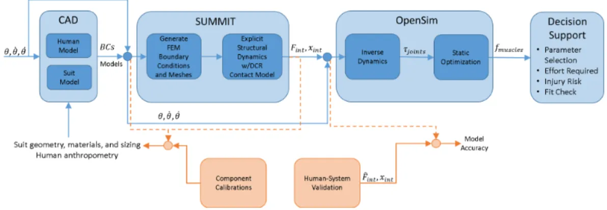
While the identification and selection process of methods and models for each of these subcomponents will be detailed further in Chapter 2, for completeness, the overall model architecture with calibration inputs is illustrated in Figure 1-4.
To tune and calibrate the integrated human-suit model, two external calibration and validation input steps are necessary. First, component-level calibrations of the modeling methods, material properties, and representative human anthropometry is integrated with the output from the CCM model to update the CAD models of the suit and human as necessary. For example, to capture the stress-strain relationship of the softgood convolutes of the DCCI Demonstrator Suit, iteration on constitutive material models and properties may be necessary to represent the suit. In addition to these component-level calibrations, which act on the CAD models, human-system
Figure 1-4: High-Level Integrated Human-Suit Model Architecture with selected com-ponent methods and calibration inputs
validation is necessary downstream of the CCM model output to validate the accuracy of the CCM model results based on experimental human-suit interation data, such as that collected with in-suit pressure sensing systems [23]. This validation step is necessary to bound the accuracy of the model, and to inform the decision support processes based on the accuracy of the model results. Furthermore, this human-suit validation can be used to guide component-level calibrations, to improve the fidelity of the CCM model and open pathways for datamatching the model to experimental data if desired.
While Figure 1-4 highlights the selections that were made for the CCM model, it is relevant to consider the pedigree of modeling techniques for resolving problems in the class of human-artifact contact problems, as discussed in Section 1.4, as these techniques were evaluated and traded based on the requirements of the model.
The CAD application used in this work was selected to be SolidWorks [24], but this can enable the use of any upstream CAD and pre-processing software as desired. A set of utilities used to easily communicate CAD mesh data, material properties, and boundary conditions was developed to support the connectivity between Solid-Works and the computational framework used for the CCM model. These utilities are detailed in Appendix D for reference. The selection of the computational framework and the internal methods used by the CCM model is detailed in Sections 2.4.2 and 2.5. Finally, the musculoskeletal model used for the integrated human-suit model is the open-source biomechanical modeling software OpenSim [25], which will be detailed
further in Section 1.5.
While the high-level of the integrated human-suit modeling environment has been detailed here, the primary focus of this work was on the development, implementation and validation of the CCM model used to resolve the human-suit contact interactions, illustrated in the Contact-Mechanics Model block of Figure 1-3. Future development of this model, as noted in Section 4.2, will involve further development of the pipeline between the CCM and OpenSim, along with component calibration and human-suit validation testing.
1.4 Human-Artifact Contact Models
While the target application of the Coupled Contact-Mechanics (CCM) model devel-oped in this work is to resolve the interactions between a human operator and EVA space suit, potentially made of rigid or softgood materials, it is relevant to consider the pedigree of human-artifact contact methods employed across a variety of domains when selecting a formulation for the CCM model. Furthermore, to enable the model to scale into geometries and materials of arbitrary definition, the CCM model should be capable of resolving the contact interactions between a human and any arbitrary contact artifact. The terminology of a contact "artifact" is used to represent any abstract entity with which the human may experience a contact interaction, such as vehicles, orthotic devices, or garments. This terminology is adopted from the work of Krüger and Wartzack [26], which considered multi-body contact dynamics between a human operator and an training device. In this work, the concept of the contact artifact is any arbitrary geometric entity which is contacted by the human, or some exogenous "impactor" entity.
When considering the development of the CCM model for use in the overall inte-grated human-suit model, it was necessary to consider the mathematical formulation in which the CCM model will be represented. Human-artifact contact, and more generally, impactor-artifact contact, is a heavily studied field, and a wide variety of mathematical- and physics-based models have been developed across a wide range
of technical domains such as human training and ergonomics [26], garment design for form and fit [5, 6, 27–31], human-exoskeleton design [32], orthotic device develop-ment [33], generalized structural mechanics [34–36], studying neural control [37], and space suit design such as this work [38].
Surveying the formulations used across these domains highlights three primary classes of human-artifact contact formulations: multi-body surrogate models, finite element method (FEM) models, and particle-based models. These classes of contact model formulations will be discussed in detail, including the primary domains that utilize each, the general theory of each formulation, and the benefits and drawbacks of each class relative to one another. These benefits and drawbacks are particularly germane to the selection of a contact model formulation to implement for the CCM model that is the subject of this work, and will be considered further in Section 2.1.
1.4.1 Multi-Body Surrogate Models
The class of human-artifact contact models referred to herein as Multi-Body Surro-gate models are those which represent the human and artifact through a construction of multiple simplicial geometric entities such as ellipsoids, coupled with a contact enforcement mechanism to prevent geometric penetration between the impactor and artifact geometric representations. The term surrogate is used as the geometric repre-sentations do not resolve unique or low-level geometric details of a human or artifact model, and instead represent the human or artifact with a simplified mathematical or geometric model, as exemplified in Figure 1-5.
This class of contact formulation has been employed primarily in musculoskeletal kinematic studies [26,39–41], with such methods used in the musculoskeletal dynamics toolkits SimTK [26,42] and DART [43], and is the primary contact formulation class employed by the Todorov:2014 physics engine [4].
As this class of contact formulations represent the human and artifact as geometric entities and do not aim to resolve low-level geometric details or internal energy states, they are computationally inexpensive relative to FEM and Particle methods [28,40], and as a result are often used in the gaming and animation industries [44]. However,
Figure 1-5: Illustration of Multi-Body Surrogate Contact Models for Dynamic Mus-culoskeletal Models as employed in SimTK [3] (left) and Todorov:2014 [4] (right) due to the nature of not resolving low-level geometric details and internal energy states at a discretized level for the system, the fidelity of this formulation is limited to the macroscopic dynamic details of the individual geometric entities, and the internal energy information is restricted to the complexity of the surrogate mathematical model employed. Furthermore, while some codes allow the use of arbitrary geometric entities [41] through Non-Uniform Rational Basis Splines (NURBS), most codes use more simplicial geometric entities for resolving contact, such as Hunt and Crossley force spheres [42].
1.4.2 Finite Element Method Models
Finite element method formulations of human-artifact contact problems have been implemented due to their ability to resolve the deformation and stress at varying levels of fidelity through the discretization of the human or artifact into well-defined tetrahedral or quadrilateral elements. Stemming from its basis of representing any entity through discretized elements, FEM has a distinct advantage in that it can describe highly complex geometries for simulation of deformation and vibration as-sociated with dynamics, without restriction to geometric continuity or thickness [45]. From this advantage, FEM contact formulations have been applied to a wide array of human-artifact contact problems, such as the deformation associated with a hand grasping a ball [46], or deformation of a human foot in response to contact with a rigid cleat [33]. The FEM formulation for human-artifact contact events has furthermore been argued as the ideal formulation of the three classes for contact problems where
both the human and artifact can deform for two reasons, as argued by Gourret and Magnenat-Thalmann [46]:
1) FEM formulations permit resolution of contact events with sliding and sticking in addition to repulsive forces. Without a means of tracking the deformations of localized regions of an entity, such as afforded by FEM, the shape of the human or artifact would not be representative to capture these modified shape changes during a contact event.
2) FEM formulations permit capturing deformations in both the human and arti-fact models at localized regions, where a simplicial or rigid body approximation may neglect such deformations on the human or artifact, depending on their relative rigid-ity. Even surrogate models with detailed NURBS representations are limited in their ability to resolve localized deformations, as the contact enforcement strategy would require the discretization of the NURBS geometry to resolve localized events - essen-tially driving towards a FEM formulation.
However, while FEM formulations provide a high degree of fidelity in modeling structural and contact mechanics for arbitrary, complex geometries, and can account for deformation of both human and artifact, they come with the drawback of a sig-nificantly higher computational expense [28] than the other classes. Despite this computational expense, applications of FEM contact formulations have been success-fully applied in capturing the effects of contact interactions between a human and flexible garment, as illustrated in Figure 1-6, which presents some similar challenges in modeling softgood human-suit interactions [5,31].
1.4.3 Particle-Based Models
The third class of human-artifact contact formulations are those referred to as Particle-based methods. These methods represent the contact artifact as a collection of dis-crete particles, often with some form of a mathematical constitutive equation between the particles to maintain continuity between the particles [6,47], as illustrated in
Fig-Figure 1-6: Illustration of FEM Human-Artifact Contact Problem resolving pressure distributions across a donned cotton shirt using Mindlin-Reissner Shell elements, per Wang et. al. [5]
ure 1-7.
Figure 1-7: Illustration of Particle-based method as adapted from the work of Volino and Magnenat-Thallman [6], representing anisotropic bending stiffness in a flexible cloth garment, while capturing the rest posture curvature of the garment in self-contact
This formulation shares some striking similarities with shell-based FEM approaches, as Particle-based schemes cannot realistically resolve the internal energy of non-thin contact artifacts by virtue of the "surface cloud" of particles, with the exception of computationally expensive peridynamic schemes [47]. However, unlike shell-based
FEM models, Particle methods do not necessarily require physics-driven constitutive relationships between the particle clouds that represent the contact artifact, and can offer significant advantages in computational speed as a result [48]. As a result of this thin surface contact artifact requirement, Particle-based methods have seen success in the garment prototyping industry, and an array of virtual "try-on" environments have been developed leveraging such methods for problems such as drape prediction and fit checks [27, 29, 48]. However, it should be noted that in these representations, while the contact artifact is deformable, the model representation of the human is typically approximated with a rigid-body definition [29], which neglects the effects of deformation on the human body. While such an assumption is valid for garment draping, for a pressurized EVA suit, this assumption has less merit resulting from the increased rigidity of the suit in pressurized conditions [23].
While the discrete nature of the Particle-based formulation does result in higher computational cost relative to a Multi-Body Surrogate representation, it is signifi-cantly less expensive relative to a FEM formulation [28,49]. Additionally, the ability to drive either mathematical- or physics-based inter-particle constitutive relationships provides a great degree of flexibility in driving the transient and static response of a contact artifact. However, without implementing a physics-based constitutive law between the particles, such as a mass-spring-damper approximation of elastic mate-rial properties, information regarding the stresses acting within the contact artifact will not be resolved. Furthermore, if the deformation of the human is also intended to be captured in a simulation, a Particle-based method will approach the effectiveness of a shell-based FEM model of the human due to its shell-like representation of the human. While this assumption may be valid while the contact artifact is less rigid relative to the human, as the contact artifact rigidity increases, the assumption that the human can be represented as an inflexible shell body weakens, as the human body deformation increases without accounting for the three-dimensional stiffness effects of the skeletal structure.
1.5 Relevance to Musculoskeletal Forward Dynamics
The musculoskeletal model component of the overall integrated human-suit model is responsible for taking in the resultant loads on the human as computed by the CCM model and determining the muscle forces necessary to achieve the motion profile. While the focus of this work is primarily on the CCM model, it is relevant to discuss the selection of the musculoskeletal modeling environment, how the CCM model interfaces with the musculoskeletal model, and a high-level view of the methodology of the musculoskeletal model.
The open source biomechanical modeling software, OpenSim [25] was selected as the component software for the musculoskeletal model portion of the integrated human-suit model . OpenSim is a powerful modeling environment for biomechanical problems, as it contains toolkits for not only musculoskeletal kinematics and kinetics, but also a means by which to use inverse dynamics [50] and static optimization [51] to compute the muscle recruitment and activation required to achieve a prescribed motion for the human model. Given the open-loop nature of the overall human-suit model noted in Section 1.3, this capability to determine the requirements on the human operator to achieve a given motion, under the external loads from the donned EVA suit as calculated by the CCM model, provides results which can be used to inform suit design to reduce risk of injury and improve efficiency for a given motion. Given the open-source nature of OpenSim, connectivity between the CCM model and the OpenSim environment can be developed to support the pipeline illustrated in Figure 1-4.
The terminology of inverse dynamics refers to the concept of taking prescribed motion data for a human along with any exogeneous forces acting on the human during that motion, the dynamics of that motion can be inverted along the lines of the common 𝐹 = 𝑚𝑎 to determine the forces the human must generate to accomplish the motion. For joint kinematics, the general equations of motion can be expressed
where M is the mass matrix, C is the Coriolis jacobian, G is the gravitational force vector, 𝜏𝑒𝑥𝑜 are the exogeneous torques acting on the human, such as those
computed by the CCM model from human-suit interactions, and 𝜏𝑟𝑒𝑞𝑢𝑖𝑟𝑒𝑑 are the
unknown torques the human must generate to achieve the motion profile through 𝜃, ˙
𝜃, and ¨𝜃.
Once the required torques to achieve the motion profile of the human under the exogenous loads prescribed from the CCM model have been determined, a process known as static optimization is employed to determine the muscle activation and re-cruitment required of the human to achieve these torques [51]. OpenSim can represent the muscles as either idealized force generators or as muscles subject to force-length-velocity constraint properties [52]. Using static optimization, the number of recruited muscles and their activation levels can be determined. This information can be used to infer fatigue and injury risk for the human and, coupled with localized pressures acting on the human as calculated by the CCM model, can potentially be used to guide suit design decisions to minimize injury and reduce the effective impedance of the suit on the human.
Further development of the pipeline between the CCM model and OpenSim is recommended, as noted in Section 4.2. However, the primary focus of this work was aimed at the CCM model component of the integrated human-suit model. The identification, selection, development, and testing of the CCM model is discussed in Chapters 2 and 3, and the structure of this discussion is reviewed in Section 1.6.
1.6 Overview of Thesis
This thesis is divided into three chapters. Chapter 2 details the methodology, devel-opment, and implementation of the Coupled Contact-Mechanics (CCM) model. It first details the selection of the class of deformable-deformable human-artifact contact formulation for the CCM model, and the identification of a computational framework in which to develop the model. The structural mechanics and contact mechanics methods considered and selected are discussed, with additional detail provided with
regards to the methodology of the explicit contact enforcement scheme used by the CCM model. The numerical algorithm which couples the structural and contact mechanics domains is described, and the software implementation of this coupled highlighted. In addition, Chapter 2 also provides a review of the efforts to enable the CCM model for parallel computation for runtime improvements. Finally, Chapter 2 concludes with a trade study identifying functional domains in which the CCM model should be employed, versus a numerically simple rigid-body contact approximation as a benchmark.
Chapter 3 discusses the methods and results of a CCM model validation study against experimental data. The contact problem domain of interest is developed into a test plan, and executed using an experimental benchtop rig. The CCM model is employed to replicate the benchtop results, and a comparative analysis of the experimental results against the CCM simulation results provided to highlight the capability of the CCM model.
Chapter 4 documents a summary of the conclusions from the trade study of Chap-ter 2 and the validation study of ChapChap-ter 3. From this, future work, and additional de-velopments and improvements for the integrated human-suit model are recommended.
Chapter 2
Methodology
This section details the methodology and development of the CCM model for use in the integrated human-suit model architecture. This involves the selection of a primary contact model formulation as noted in Section 1.4, and the identification of a computational framework in which to implement the model. With a framework and model architecture selected, this section identifies the constitutive model selected for resolving structural mechanics, as well as the contact enforcement method used to model the deformable-deformable human-artifact contact problems germane to this work. A primer on contact enforcement methods is provided for background on alternate contact methods, along with a detailed discussion of the contact enforcement method selected for the CCM model. The means and algorithm by which the CCM model couples structural and contact mechanics is addressed, and the implications for this software development highlighted. Furthermore, the extension of the CCM model to enable parallel computation is reviewed, with computational scaling studies performed. Finally, to identify the problem domains in which the CCM model should be employed over a simplified, less expensive rigid body contact model, a trade study is performed. This trade study considers a range of relative model parameters, such as the ratio of Young’s Moduli between an impactor and artifact, to identify the computational cost versus simulation accuracy associated with each model. From the results of this trade study, recommendations can be made regarding when the full fidelity CCM model should be used for improved accuracy in exchange for runtime
versus a simplified rigid body assumption.
2.1 Model Architecture Selection
One of the first steps in the development of a computational model for deformable human-artifact contact was the selection of a modeling approach. In Section 1.4, three primary model architectures were discussed, namely Multi-Body Surrogate models, Finite Element Method-based models and Particle-based models. As each architec-ture has merits and drawbacks, a trade had to be performed to select an approach for modeling human-suit contact problems.
Section 1.4 details the fundamentals of each of these methods and highlights some of the benefits and drawbacks associated with each method. To trade between these architectures, a set of desired model attributes were defined to score each architec-ture. The selected attributes are:
1) Computational Expense
2) Fidelity of Contact Enforcement 3) Fidelity of Structural Mechanics 4) Arbitrary Model Geometry Capability
The first attribute, computational expense, as defined for the sake of this trade is the total computational runtime required to fully resolve a transient problem. Note that this distinction for runtime, and not also computational complexity, was explic-itly selected to not artificially debit methods that scale in parallel computation. The second attribute, fidelity of contact enforcement, represents both the accuracy of the contact model and the ability to interrogate low-level data from the model. The third attribute, fidelity of structural mechanics, represents the accuracy of the model to re-solve resultant deformations and stresses, and also the ability to interrogate low-level structural data from the model. Lastly, the fourth attribute, arbitrary model geome-try capability, represents the ability for the model to capture any arbitrary geometric
shape for the human or artifact.
With these metrics in mind, and based on the literature discussed in Section 1.4, a comparative trade stackup was completed. The results of this qualitative trade are represented quantitatively in Table 2.1, where a higher numerical ranking represents the more capable model.
Metric Multi-BodySurrogate Models
FEM-based
Models Particle-basedModels Computational Expense 3 1 2 Fidelity of Contact Enforcement 1 3 3 Fidelity of Structural Mechanics 2 3 1 Arbitrary Model Geometry Capability 1 3 3 Total Score 7 10 9
Table 2.1: Summary of Model Architecture Trade
While FEM-based models may be known to incur the highest computational ex-pense of the architectures, it offers a framework that can account for arbitrary ge-ometries while resolving both contact and structural mechanics with variable resolu-tion. Particle-based methods, while less computationally expensive, cannot resolve structural mechanics beyond shell approximations. Due to the capability to resolve arbitrary geometries, and improved fidelity in structural mechanics, a FEM-based architectural approach was selected for development of this human-artifact contact model. With a FEM-based architecture selected, the development of the model could be decomposed into the selection or development of two components: a structural mechanics solver, and a contact enforcement method.
2.2 Structural Mechanics Framework and Model
To resolve the internal stresses in the human and artifact that result from a contact impulse or other exogeneous force, a structural mechanics computational framework is necessary. A wide variety of frameworks exist, including a wide range of com-mercially available codes such as ANSYS. Some commercial codes already contain contact resolution methods as well [34]. However, the ability to integrate with or modify these codes are limited due to their closed-source nature. Furthermore, their ability to scale in parallel computation may be limited [34] or restricted to specific contact enforcement methods [35]. This is not to say that these codes are not effec-tive and capable, but for the purposes of this project and due to these limitations, an open-source computational framework was desired.
The computational framework SUMMIT, developed at MIT by Professor Raul Radovitzky, is an open-architecture structural and multiphysics environment. It sup-ports both continuous and discontinuous Galerkin methods for multiphysics prob-lems [53], and a wide array of constitutive material models [54, 55]. It also has extensive parallelization support for its structural methods through METIS and ParMETIS [56]. Lastly, it contains both rigid body contact mechanics methods, and a legacy explicit contact mechanics model that will be discussed in Section 2.4.2. Due to the open architecture design of SUMMIT allowing users to directly interact with and modify the source code to integrate external models, such as contact, cou-pled with the pre-existing capabilities of SUMMIT in parallelization and modeling methods, SUMMIT was selected as the computational framework for this work.
2.3 Constitutive Material Models
The SUMMIT computational framework supports a wide variety of constitutive ma-terial models. While the intent of this work is not to identify the appropriate consti-tutive model to represent the various materials used in the Mark III or Demonstrator Suit, it is germane to identify a constitutive model that is appropriate for
simulat-ing large displacement simulations with coupled contact interactions. Two primary material models were considered for use in this work: a linear elastic model and a non-linear Neo-Hookean model.
The first constitutive model considered in this study was the application of an isotropic linear elastic model. The stress response of this constitutive model can be expressed by
𝜎𝑖𝑗 = 𝜆𝛿𝑖𝑗𝜖𝑘𝑘+ 𝜇(𝜖𝑖𝑗 + 𝜖𝑗𝑖) (2.1)
where 𝜎 is the Cauchy stress, 𝜆 is the first Lamé coefficient, 𝛿 is the Kronecker delta, 𝜖 is the strain, and 𝜇 is the second Lamé coefficient, with subscripts 𝑖, 𝑗, and 𝑘 representing the principal axes [57].
This linear constitutive model was initially evaluated for the baseline material model for the structural mechanics system. However, due to the nature of the large deformations present in the transient simulations considered for contact, this material model would unrealistically deform entities. This issue becomes apparent when, as strain increases with deformation, stress increases in a similar linear fashion. For large deformations, this results in unrealistic stress-strain relationships, and as such, was not selected for the primary constitutive model in this study.
The second constitutive model considered in this work, and the model that was selected and used, is the nonlinear Neo-Hookean hyperelastic model. It is relevant to note that in hyperelastic formulations, a nonlinear relationship between stress and strain is permitted, which is advantageous to large deformation problems, such as those involving contact. For this constitutive model, the primary governing equations are for the strain energy density function
𝑊 = 𝜆 2ln
2(𝐽 ) − 𝜇ln(𝐽 ) +𝜇
2(tr(𝐶) − 3) (2.2)
where 𝜆 and 𝜇 are the first and second Lamé coefficients, J is the determinant of the deformation gradient, and C is the right-Cauchy Green deformation tensor [58]. From this strain energy density definition, the response can be written as
𝑆𝑖𝑗 = 𝐶𝑖𝑗−1𝜆ln(𝐽 ) + 𝜇(𝛿𝑖𝑗 − 𝐶𝑖𝑗−1) (2.3)
where S represents the second Piola Kirchhoff stress [54]. The Neo-Hookean constitutive model was found to be an effective baseline for this contact-mechanics model study, as unlike the linear elastic model, the Neo-Hookean model could re-solve large deformations without generating unrealistic stress responses within the material. However, it should be noted that a full analysis of appropriate constitutive models will be necessary to accommodate the unique material properties associated with softgood material weaves in EVA suits. Further investigation into additional constitutive models, including superelastic models, is recommended to consider mod-els which can accommodate the multiple static equilibrium postures of softgood suits such as the Demonstrator suit. However, for the purposes of the development of this model, the nonlinear Neo-Hookean constitutive model is sufficient.
2.4 Contact Mechanics Model
As highlighted in Section 1.2, to resolve the interactions between a human operator and a donned EVA suit, contact between the suit and the human, and self-contact within the suit must be captured by this model. As a result, a contact enforcement scheme that is capable of enforcing contact for arbitrary geometries in both human-artifact and human-artifact-human-artifact interactions must be identified or developed. This iden-tification is a nontrivial process. To implement a nonlinear contact mechanics solver within the context of a finite element analysis, special care must be considered in addressing the two primary steps in resolving contact, beyond considering the inte-gration of these methods into the formulation for structural mechanics:
1) Contact Search
2) Contact Constraint Enforcement
compu-tational domain for any geometric penetration that violates the defined contact con-straint. A wide range of formulations exist, the simplest being the nearest-neighbor approach [59], in which a master surface is checked against a slave surface to enforce the geometric contact constraint. However, this approach is ineffective for problems involving self-contact or nondeterministic contact pairings. To resolve the ineffec-tiveness of nearest-neighbor, methods such as a global search method [59], or a two step iteration can be employed [60]. Additionally, the geometry which is considered for determining geometric proximity can vary to use a single or combination of the finite element nodes, edges, centroids, or quadrature points to detect geometric pen-etration. Furthermore, for parallel computation, the manner by which the domain is partitioned plays a large role in the selection of the method and complexity of the contact search, which will be discussed further in Section 2.7.2.
Once a contact constraint is found to be violated through the contact search, the nature by which the constraint is enforced is the Contact Constraint Enforcement step. Several categories of contact enforcement schemes have been proposed and implemented in finite element applications. In general, however, these schemes can be categorized into one of three categories, namely, contact penalty methods, Lagrangian multiplier methods, augmented Lagrangian methods [60]. While an extensive review is not necessary for the intent of this work, it is relevant to provide a basic summary of these methods when introducing the method employed in this model. To begin, however, it should be noted that the the general equation of motion for a problem involving contact can be expressed by
𝑀 ¨𝑥 + 𝜕𝑄( ˙𝑥, 𝑥)
𝜕𝑥 = 𝑓𝑒𝑥+ 𝑓𝑐𝑜𝑛𝑡𝑎𝑐𝑡 (2.4)
where M is the mass matrix, Q is the internal energy, fex are exogenous forces,
fcontact is the force necessary to comply with the contact constraint, and 𝑥 is the
position vector. The means by which this contact force is calculated and introduced into the equation of motion is the main differentiation between these methods.
2.4.1 Pedigree of Contact Enforcement Methods
Contact Penalty MethodsFor a contact penalty method, the contact force of Equation 2.4 can be generally represented by a mechanical spring, expressed as
𝑓𝑐𝑜𝑛𝑡𝑎𝑐𝑡 = 𝐾𝑃Δ (2.5)
Here, x is the finite location of interest, xΓ is the nearest location to x on the
contact constraint, and KP is the contact penalty parameter. Figure 2-1 provides an
illustration of this contact force representation.
Figure 2-1: Contact Penalty Method Force Formulation
The distance between Γ1 and Γ2 form the penetration parameter ∆ in this frame
by
Δ = (𝑥1− 𝑥2),
Δ ≥ 0 (2.6)
It should be noted that ∆ is a nonlinear piecewise defined function, effectively representing a compression-only spring which ensures when the contact constraint is not violated, ∆ is 0 and thus fcontact is also 0. While this formulation is relatively
coefficient KP. If KP is too large, the contact enforcement will dominate the forces
in a given time step in the simulation, and in an explicit scheme, can contribute to instability [36]. Furthermore, the contact constraint can only be exactly represented as KP tends to infinity, which is not realizable in computational practicality. As
a result, the contact constraint is not necessarily completely enforced, and some geometric penetration may occur. Regardless, penalty methods are relatively common [36, 60, 61], and SUMMIT also includes a contact penalty scheme for resolving rigid body contact problems, which will be discussed further in Section 2.8.
Lagrangian Multiplier Methods
Methods that fall into the Lagrangian Multiplier class take on the general form of Equation 2.4, with fcontact being replaced by
𝑀 ¨𝑥 + 𝜕𝑄( ˙𝑥, 𝑥)
𝜕𝑥 = 𝑓𝑒𝑥+ 𝐺
𝑇𝜆 (2.7)
where G represents the constrained nodal displacements along the contact bound-ary, and must satisfy
𝐺[𝑥 + 𝑢] = 0 (2.8)
where x are the nodal positions and u are the nodal displacement vectors [60]. Equations 2.7 and 2.8 are solved as a system to find 𝜆, which is the Lagrange multi-plier from which these methods derive their name [60]. Many computational frame-works incorporate Lagrangian Multiplier methods for contact enforcement, including ANSYS [34] and ADINA [62]. Lagrange multiplier methods are more numerically intensive to satisfy relative to penalty methods [36], but are notably more effective for exactly enforcing the contact constraint [63].
Augmented Lagrangian Methods
To address the limitations of the non-infinte KPused in contact penalty methods, an
![Figure 1-1: NASA Mark III EVA Suit [1] (left) and DCCI Demonstrator LEA Suit [2]](https://thumb-eu.123doks.com/thumbv2/123doknet/14507026.528955/25.918.288.629.103.376/figure-nasa-mark-iii-suit-dcci-demonstrator-suit.webp)
![Figure 2-14: Parallel Scaling Study Results for Contact-Mechanics Model Compo- Compo-nents, with Contact Mechanics Iteration Time using Equal-Elements (EE) Static Partitioning [blue], Contact Mechanics Iteration Time using Recursive Coordinate Bisectioning](https://thumb-eu.123doks.com/thumbv2/123doknet/14507026.528955/75.918.203.715.415.723/mechanics-mechanics-iteration-partitioning-mechanics-iteration-coordinate-bisectioning.webp)