Coordinated Dynamic Planning for Air and Space Operations
by
Matthew Christian Wroten
B.S. Operations Research, Mathematics
United States Air Force Academy, 2003
SUBMITTED TO THE SLOAN SCHOOL OF MANAGEMENT IN PARTIAL FULFILLMENT OF THE REQUIREMENTS FOR THE DEGREE OF
MASTER OF SCIENCE IN OPERATIONS RESEARCH
at theMASSACHUSETTS INSTITUTE OF TECHNOLOGY
June 2005
MASISACHUS I7S INSTTUTE OF TECHNOLOGY
JUN 2 3 LIBRARIE05
LIBRARIES
© 2005 Matthew C. Wroten. All rights reserved.
The author hereby grants to MIT permission to reproduce and to distribute publicly paper and electronic copies of this thesis document in whole or in part.
-4 /
Signature of Author:
(
I 6q A d A
Sloan School of Management Interdepartmental Program in Operations Research
06 May 2005
Approved by:
'-'l
I
":I
Stephan E. Kolitz Charles Stark Draper Laboratory, Inc. Technical Supervisor. '
/"
Certified by: . - -
-John-Paul Clarke Associate Professor, Department of Aeronautics and Astronautics Thesis Advisor
Accepted by:
John N. Tsitsiklis Professor, Department of Electrical Engineering and Computer Science Co-Director, Operations Research Center
Coordinated Dynamic Planning for Air and Space Operations
by
Matthew C. Wroten
Submitted to the Sloan School of Management on 06 May 2005 in Partial Fulfillment of the Requirements
for the Degree of Master of Science in Operations Research
ABSTRACT
Planners of military air and space operations in a battlefield environment seek to allocate
resources against targets in a way that best achieves the objectives of the commander. In
future conflicts, the presence of new types of assets, such as tactical space-based sensors and Operationally Responsive Spacelift (ORS) assets, will add complexity to air andspace operations decisions. In order to best achieve objectives, planners of different types
of assets will likely need to work collaboratively when formulating tasking for their
resources. The purpose of this research is to investigate the challenges of air and space
collaboration and to quantify its potential benefit.We model a future threat scenario involving a rogue nation with Weapons of
Mass Destruction (WMD) capability and a significant air defense force. We consider
three separately-controlled resource groups - aircraft, satellites, and ORS assets - to
combat the target threat. In addition, we formulate a top-level coordination controller,
whose job it is to effect collaborative decision-making among resource groups.Using a combination of pre-existing software and new algorithms, we develop the
Coordinated Dynamic Air and Space Operations Control System (CDASOCS), which
simulates controller-generated plans in a battlefield environment recurring over multiple
planning periods. New algorithms are presented for both the top-level coordination
controller and the ORS controller. The benefits of resource coordination in CDASOCS
are demonstrated in three main experiments along with several parameter variation tests.
Thesis Supervisor:
Professor John-Paul Clarke
Title:
Professor of Aeronautics
Professor, Department of Aeronautics and Astronautics
Technical Supervisor: Dr. Stephan E. Kolitz
Title:
Principle Member of the Technical Staff
The Charles Stark Draper Laboratory, Inc.
ACKNOWLEDGEMENTS
I would like to express my appreciation to all of the individuals that have helped
me over the past two years. First, I want to thank Dr. Stephan Kolitz of Draper
Laboratory. The deep commitment he has to his students transcends the expectations of
an advisor. His wisdom and guidance have helped me grow as a student and as anindividual.
I would also like to thank Professor John-Paul Clarke for his willingness to ask
tough questions and challenge assumptions. He has a remarkable ability to provide a
unique perspective to any problem and I thank him for being my advisor.
Next, I want to thank Dr. Charlie Strauss, Dr. Owen Deutsch, and Dr. Pete
Scheidler of Draper Laboratory for their help on the GC2LAO project. They were always
eager to answer my questions, patient in teaching me new concepts, and gracious with
their time.
I would like to thank MIT, The Charles Stark Draper Laboratory, the Air Force
and the Air Force Academy for giving me this chance to further my education. Also, I
thank Lt. Col. Andrew Armacost for being an inspiring teacher and for encouraging this
opportunity.
I want to thank my friends at Draper, especially Caleb and Randal, for the good
conversations over coffee, the time spent together getting through the rigors of classes,
and the exceptional companionship - Y'all are gonna be missed!
Next, I want to thank my family for their abiding love and support. Mom and
Dad, Michael and Kathryn, you have always been very encouraging of whatever I do; I
have truly been blessed with a great family.
Lastly and most importantly, I thank my wife, Cori. I could not have done this without you. Your love and devotion mean more to me than anything in the world.
This thesis was prepared at The Charles Stark Draper Laboratory, Inc. under Internal
Company Sponsored Research Project 12596-001, Global Command and Control for
Integrated Air Operations (GC2IAO).
Publication of this thesis does not constitute approval by Draper or the sponsoring agency
of the findings or conclusions contained therein. It is published for the exchange and
stimulation of ideas.
The views expressed in this thesis are those of the author and do not reflect the official
policy or position of the United States Air Force, Department of Defense, or The U.S.
Government.
/
/ ,/?7
Matthew C. Wroten, 2nd LT., USAF Date
Table of Contents
TABLE OF CONTENTS ... 7
LIST OF FIGURES ... 11
LIST O F TAB LES ... 13
1 INTRODUCTION ... 15
1.1 THE TARGETING CYCLE . ... 15
1.2 THESIS OVERVIEW ... 18
2 JOINT AIR AND SPACE OPERATIONS ... 21
2.1 SC EN A R I ... 21
2.2 RESOURCES ... ... 22
2.2.1 Space Force Enhancement Assets ... 24
2.2.2 Air Assets ... 25
2.2.3 Space Force Application Assets ... 26
2.3 COMMAND AND CONTROL ... 28
2.3.1 Day-to-Day Planning ... 29
2.3.2 Coordination between AOCs and AOC Divisions ... ... 32
2.4 PROBLEM STATEMENT ... 33
3 MODEL DEVELOPMENT ... 35
3.1 MODELING ASSUMPTIONS ... 35
3.2 FUNCTIONAL SYSTEM ... 38
3.2. 1 Functional Architecture ... 39
3.2.2 Planning and Re-Planning ... 40
3.3 THE COORDINATION CONTROLLER ... 41
3.3. 1 C C Inputs... ... 42
3.3.2 CC L)ecisions ... 46
3.3.3 CC Objectives ... ... 49
3.3.4 C C C onstraints ... 51
3.4 THE ORS CONTROLLER ... 53
3.4.1 ORSC Assumptions ... 53
3.4.2 ORSC Inputs ... 54
3.4.3 ORSC Decisions ... 55
3.4.5 ORSC Constraints ... 61
3.5 EXISTING FUNCTIONS ... 63
4 ALGORITHMS AND FORMULATIONS ... ... 65
4.1 LITERATURE REVIEW ... 66
4.1.1 Static Formulation ... 67
4.1.2 Dynamic Formulation ... 68
4.1.3 Combination of Both ... 70
4.2 SOFTWARE ARCHITECTURE AND CONSTRAINTS ... 70
4.3 EXISTING AIRCRAFT PLANNER (IBMS 1.0) ... 7... 73
4.4 EXISTING SATELLITE PLANNER (EPOS 2.0) ... 74
4.5 COORDINATION CONTROLLER ALGORITHMS ... ... 75
4.5.1 Nominal Air and Space Operations Coordinator (NASOC) ... 77
4.5.2 Heuristic Air and Space Operations Coordinator (HASOC) ... 81
4.5.3 Optimizing Air and Space Operations Coordinator (OASOC) . ... 87
4.6 ORSC ALGORITHMS ... 90
4.6.1 Heuristic ORS Controller (HORSC) . ... ... 91
4.6.2 Optimizing ORS Controller (OORSC) ... 93
5 TESTING AND ANALYSIS ... 99
5.1 SOFTWARE INTEGRATION ... 99
5.2 SCENARIOS ... ... 101
5.2.1 Fixed Scenario Attributes ... 103
5.2.2 Changeable Parameters ... 107
5.2.3 Base Scenario Description ... 111
5.3 PRIMARY EXPERIMENTS ... 115
5.3.1 Experiment 1: Addition of ORSC to Base Scenario ... 116
5.3.2 Experiment 2: Addition of SATC to Base Scenario ... ... 118
5.3.3 Experiment 3: Addition of Both ORSC and SATC to Base Scenario ... 121
5.4 PARAMETRIC VARIATIONS ... 126
5.4.1 CC/ORSC Parameter Variations ... ... 126
5.4.2 EPOS Parameter Variations ... 131
5.4.3 IBMS Parameter Variations ... 133
5.4.4 SIM Parameter Variations ... 136
6 CONCLUSIONS AND FUTURE WORK ... 141
6.1 SUMMARY ... 141
APPENDIX A: GLOSSARY OF ACRONYMS ... 145 REFERENCES: ... 148
List of Figures
Figure 1-1: Target Categories (adapted from [14]) ... 16
Figure 1-2: Joint Targeting Cycle (adapted from [14]) ... 17
Figure 2-1: Resources of a future JAOC ... 23
Figure 2-2: Phases of the Joint Air and Space Tasking Cycle (adapted from [13]) ... 29
Figure 2-3: Information Flows in the JASTC ... ... ... 30
Figure 2-4: ATO cycle ... 31
Figure 3-1: Functional Coordinated Air and Space Operations System (FCASOS) ... 39
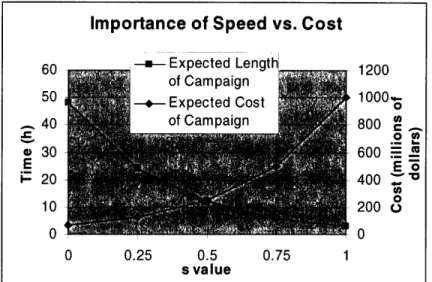
Figure 3-2: Inportance of Speed vs. Cost Parameter ... 44
Figure 3-3: CC Information Flow ...
46
Figure 3-4: Strike/BDA scenario ...
47
Figure 3-5: Illustration of Launch Configurations ...
56
Figure 3-6: New Representation of Launch Configurations ... 56
Figure 3-7: Example Time Proximity Factor Weighting ...
60
Figure 4-1: Coordinated Dynamic Air and Space Operations Control System (CDASOCS) ... 71
Figure 4-2: Coordination Controller Algorithmic Flowchart ... 77
Figure 4-3: P(destruction) graph ...
92
Figure 5-1: Illustration of Information Sharing in CDASOCS ... 100
Figure 5-2: Scenario Geography ... 102
Figure 5-3: Target Scenario 1 ... 109
Figure 5-4: Target Scenario 2 ...
110
Figure 5-5: Target Damage by Category ...
... 113
Figure 5-6: Aircraft attritions by Type ... 114
Figure 5-7: Kill Chain Progression ... 115
Figure 5-8: Damage Comparison for Experiment 1 ... 117
Figure 5-9: Kill Chain Progression for AC only Scenario ... 120
Figure 5-10: Kill Chain Progression for AC and SATC Scenario ... 120
Figure 5-11: Kill Chain Progression for AC and SATC Coordinated Scenario ... 121
Figure 5-13: Kill Chain Progression for AC, ORSC, and SATC Coordinated Scenario 123
Figure 5-14: Number of Targets Remaining for Experiment 3 ... 124
Figure 5-15: Damage Comparison for Experiment 3 ... 125
Figure 5-16: Comparison of Resource Allocation for Experiment 3 ... 125
Figure 5-17: ADF Comparison for Experiment 4 ... 127
Figure 5-18: Kill Chain Progression for Scenario A in Experiment 6 ... 130
Figure 5-19: Kill Chain Progression for Scenario B in Experiment 6 ... 130
Figure 5-20: ADF Comparison for Experiment 6 ... 131
Figure 5-21: Kill-Chain Progression for Coordinated Scenario in Experiment 10 ... 134
Figure 5-22: Kill-Chain Progression for IPB=O case in Experiment 10 ... 135
List of Tables
Table 2- 1: Partial Listing of Current and Planned ISR and Strike Aircraft ... 26
Table 3-1: Sample Inputs into CC ... 43
Table 5-1: AC Statistics ...
112
Table 5-2: Performance Stats Comparison for Experiment 1 ... 118
Table 5-3: Performance Stats Comparison for Experiment 2 ... 119
Table 5-4: Basic Performance Statistics for Experiment 3 ... 122
Table 5-5: Basic Performance Statistics for Experiment 5 ... 128
Table 5-6: Basic Performance Statistics for Experiment 6 ... 129
Table 5-7: Basic Performance Statistics Comparison for Experiment 7 ... 132
Table 5-8: Basic Performance Statistics for Experiment 10 ... 135
Table 5-9: Basic Performance Statistics for Experiment 12 ... 138
1 Introduction
In a military campaign, air and space operations planners have a wealth of information to
consider when producing operational plans. Commander's objectives, target lists,
intelligence reports, and analyses of capabilities are just some of the factors that
contribute to air and space decision-making. Using these inputs, it is the goal of planners to assign resources to missions in the way that best achieves the commander's objectives with as little risk and cost as possible. In the case of air operations, these resourceassignment decisions are guided by a process known as the Targeting Cycle.
1.1 The Targeting Cycle
Joint Publication 3-60, Joint Doctrine For Targeting, defines a target as "an area,
complex, installation, force, equipment, capability, function, or behavior identified for
possible action to support the commander's objectives, guidance, and intent" [14]. There
are two major categories of targets within military operations: planned and immediate.
Planned targets are those entities that have been labeled as targets since before the
execution phase of the current battle plan. Immediate targets are those entities that
become targets during the execution phase. If a target poses an imminent danger, is
rapidly fleeting, or is labeled as high-value, it can be further classified as aTime-Sensitive Target (TST). In Figure 1-1, the different target categories are displayed. Note
that TSTs can come from any target category.
Scheduled On-Call Unplanned
Targets (Known) Unanticipated Targets (Unknown) Ill
Figure 1-1: Target Categories (adaptedfrom [14])
Operations centers create missions for planned targets using the Joint Targeting Cycle.
This cycle outlines to commanders the specific steps involved with targeting. It is a model that is used across a range of military domains and so is discussed below without any specific context. Phases of the Joint Targeting Cycle are shown in Figure 1-2.In the first phase of the cycle, Commander's Objectives, Guidance, and Intent, it
is the job of the commander to present "clear, quantifiable, and achievable objectives
[that] lead to the successful realization of national security goals through a targeting
solution" [14]. An important component of this phase is Identifying Centers of Gravity
(COG). Centers of Gravity, as defined by Joint Pub 3-0, are "those characteristics,
capabilities, or sources of power from which a military force derives its freedom of
I
M
[old
Ir(= r r r
action, physical strength, or will to fight." They might include actual military targets or
less tangible forces such as public support. In addition to identifying COGs, the commander must provide objectives as well as Measures of Effectiveness (MOE) foreach COG. MOEs are metrics used to quantify achievement of the objectives.
In Phase 2, Target Development, Validation, Nomination, and Prioritization,
planners identify targets, validate them as lawful and viable targets, nominate them to
higher channels for approval, and prioritize them according to importance. The result of
this phase is a prioritized Target Nomination List (TNL) that includes the desired
outcome for each target along with any stipulations.
(1)
Commander's
Objectives
I { \ II I tO)Combat
TargetTarget
L
I-(5) Dlnnint nnrl (4) Force I AssignmentFigure 1-2: Joint Targeting Cycle (adaptedfrom [141)
Planners match specific forces to use against each target in phase 3, the
Capabilities Analysis phase. Possible mission combinations are analyzed using
mathematical models that take into account weapon system ability and target
characteristics. Once this is accomplished, planners form a recommendation of the most
effective grouping of resources to use against each target.
r-... I~~~~~~~~~~~~~~~~~~
I I
it I
I I Icti 11III V Gai i% I
In Phase 4, Commander's Decision and Force Assignment, the commander
reviews and finalizes target recommendations to ensure a synergistic integration of
resources.
In Phase 5, Mission Planning and Force Execution, mission specific details such
as airplane routing and rendezvous points are determined by planners. Once this is
completed, the final plan, as formulated in phases one through five, commences.Intelligence experts consolidate data from various sources and evaluate the
success of missions in Phase 6, the Combat Assessment phase. This phase is composed of
three sub-parts: Battle Damage Assessment (BDA), Munitions Effectiveness Assessment
(MEA), and future targeting recommendations [14].1.2 Thesis Overview
This scope of this research involves air and space operations that are guided by the Targeting Cycle. The thesis is organized into six chapters. The theme of each chapter subsequent to this one is as follows:
Chapter 2 - Joint Air and Space Operations: We present a future threat
scenario and further specify the Targeting Cycle under the operational framework that
would likely deal with the threat. We outline a Concept of Operations for the scenario,including descriptions of the types of resources assumed and a specific command and
control structure. Finally, we define the Air and Space Operations Planning Problem(ASOPP) to which the rest of the thesis is directed.
Chapter 3 - Model Development: A functional model of the problem is
presented to frame it from a mathematical perspective. Modeling assumptions are made
and the inputs, decisions, objectives, and constraints of every functional component are
discussed. Two of the functional components given in this chapter represent new
contributions toward researching the coordination of air and space resources.
Chapter 4 - Algorithms and Formulations: The purpose of this chapter is to
formulate new algorithms that provide the decision-making logic to the functionalcomponents of Chapter 3. We research previous formulations and solution methods that
have been, or could be applied to, the Targeting Cycle. We list certain restrictions on thealgorithms arising from software constraints. Also, three pre-existing pieces of software
that are employed in the system are described. Lastly, we present the fivealgorithms/formulations that represent new contributions in this thesis.
Chapter 5 - Testing and Analysis: In this chapter, the algorithms of Chapter 4
are tested on a simulation, and their results analyzed. First, a complete picture of the
software implementation and integration is shown. Then, a description is provided of the parameter values used in various testing scenarios. Next, three main experiments are used to quantify the benefit of adding space to air operations as well as coordinating among resources. Finally, a series of miscellaneous tests are conducted to analyze the effects ofvarying individual parameters within each component of the system.
Chapter 6 - Conclusions and Future Work: In the last chapter, a summary of
what is accomplished is given, including major insights gained from the research. A final section is devoted to areas of future research for possible extensions to what is done here.2 Joint Air and Space Operations
This thesis focuses on air and space operations that are planned for and directed by a Joint Air Operations Center (JAOC) in the year 2025, where a JAOC is the assumed entity through which all resource tasking is generated. In this chapter, a war-time scenario is presented in which the JAOC, following doctrine from the targeting cycle, is
tasked to subdue an enemy threat using military force. We describe assumptions
regarding the general threat scenario and available resources. We present a Concept of
Operations (CONOPS), which is a broad outline of the operation from a military
perspective, and discuss the organization of the JAOC. Because some resources in the scenario do not yet exist, the CONOPS is necessarily hypothetical in nature. It is the goalof this chapter to specify the threat scenario and CONOPS and to define the operational
problem to which the rest of the thesis is directed.
2.1 Scenario
Within the next 30 years, it is possible that the US military will be called upon to
suppress a hostile nation seeking to proliferate and/or detonate Weapons of Mass
Destruction (WMD). Such a nation might have a large conventional military, significant
Integrated Air Defense Systems (IADS), and could pose an immediate threat to the US,
or to a US ally. If this situation arises without warning, the US might not have anysignificant land forces staged in the region. Given a National Command Authority
directive to completely negate the threat through the use of military force (with certaineconomic, political, and environmental stipulations), it would then become the job of the
Joint Force Commander (JFC) in charge of all forces in that region to formulate military
objectives, decide which forces to utilize, and carryout the execution of the ensuing
military campaign. Because of the urgency of the situation, it is likely the JFC would rely
heavily on resources that are quickly accessible, namely air and space power, until other
resources arrive. Under these assumptions, the following military objectives are plausible
for the first few days of the campaign:1. Search for and negate high value targets (WMD sites, Command and
Control facilities, etc.)
2. Search for and negate other key conventional targets (artillery,
infantry units)
3. Establish Air Superiority
4. Avoid civilian casualties and damage to the economic infrastructure
5. Prepare for a subsequent US/coalition conventional force invasion
In addition to tasking the JAOC with these objectives, the JFC would also outline, for
each objective, quantifiable measures of success. The remainder of this chapter is used to
describe how the JAOC would likely function in this setting. It is important to understand the operation of, and decision making in a JAOC as well as information sharing that goeson between air and space planners. We describe the JAOC's available resources, its
command and control structure, and aspects of its day-to-day operation.
2.2 Resources
New types of air and space resources will likely be developed and made operational within the next 20 to 30 years. Rapidly advancing technology and the need to respond to
a variety of different threats will push this development and, as a result, will cause some
of the current inventory to become obsolete. In an attempt to remain as up-to-date as
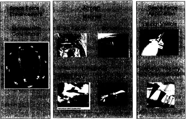
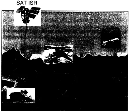
possible, we include in this research some vehicles that are presently operational as well as some still in the concept or design phase. In Figure 2-1, the three categories of resources of this future operational scenario are shown. For each category, a section isdevoted to explain the assumed capabilities of that resource set. Resources include:
1. Space Force Enhancement assets (ISR only)
2. Air assets (ISR and Strike)
3. Space Force Application weapon systems (Strike and one-time ISR)
Figure 2-1: Resources of a future JAOC
The range, of available resources is confined to platforms capable of performing strike
and/or Intelligence Surveillance and Reconnaissance (ISR) missions. A strike mission
involves the planned destruction of one or more targets through the use of air-to-ground(or space-to-ground) munitions. An ISR mission, on the other hand, seeks to gain
information about a target or an area of interest, usually through the use of imaging
sensors. ISR missions either involve the continuous, or near continuous, collection of
data over a period of time (surveillance) or the one time tasking of a resource to image a
target and return to base (reconnaissance). It is possible for a single resource to perform both strike and ISR on the same mission. Finally, it is assumed that an unlimited number of mission-support vehicles, e.g., air refueling aircraft, exist and are always availablewhen needed.
2.2.1 Space Force Enhancement Assets
Space Force Enhancement, as laid out in Joint Publication 3-14, Joint Doctrine for Space
Operations, includes operations that "multiply joint force effectiveness by enhancing
battlespace awareness and providing needed warfighter support" [12]. Currently, these
operations are directed by a space version of the JAOC (Space AOC). The types of SpaceForce Enhancement assets considered in this research are ISR-capable microsatellites
(microsats) that are placed in a defined constellation. Microsats constitute a new
generation of imaging satellites that are currently still being developed. According to
[16], they will be approximately three feet in diameter, 1.5 feet tall, and weigh no more than 220 pounds. There are two main benefits to developing and using microsats over existing conventional satellites. First, the cost to launch a microsat is much less due to its decreased weight. Secondly, the fuel requirement, once on orbit, is much reduced. ISR microsats are being designed to launch into Low-Earth Orbit (LEO) [23].Because of the low-cost nature of microsats, there will likely be a larger number
of satellites in future ISR constellations than what is currently used. We allow for two possible constellations in this scenario - one with 36 satellites and one with 72. Also, thefollowing four assumptions are made regarding satellite orbits: 1) all orbits are circular
and have the same altitude, 2) the angular spacing of satellites within an orbital plane is constant, 3) the relative phasing between planes is constant, and 4) once in orbit, satellite maneuvering is confined to station-keeping. Under these assumptions, there will be sometrade-off between target coverage, the number of satellites in orbit, and the quality of
sensor measurements [1]. Achieving effective target coverage requires either more
satellites with a lower altitude or fewer satellites with a higher altitude. While the former
case increases cost, the later decreases the quality of sensor measurements. At any rate,
this is a tradeoff that satellite planners make well before the start of the campaign.It is assumed that each satellite carries exactly one sensor. The three types of sensors most likely to be put on microsats include: infrared (IR), visual, and radar. IR sensors record invisible infrared light and are used primarily to detect medium to
long-range missile launches, not for ISR purposes. Visual sensor technology can provide
reasonably high-resolution images (if the satellites are close enough to the earth) but is
limited by both weather and daylight. Radar sensors can also provide high-quality images
and are not affected by clouds or darkness. However, the more powerful the radar sensor, the more fuel it consumes. For ISR microsatellites, there seems to be a tradeoff between the relatively low fuel consumption of visual sensors versus the ability to operate in anyweather conditions/time of day of radar sensors. The only assumption made here
regarding each satellite's sensor is that it has high enough resolution to positively identify, with reasonable accuracy, the types of targets considered in this scenario.2.2.2 Air Assets
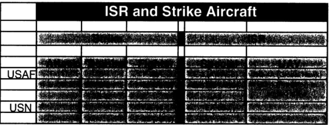
Air assets capable of ISR and strike include attack, bomber, fighter, and UAV aircraft.
Table 2-1, while not an exhaustive inventory, lists operational and developmental aircraft that serve in this capacity. Only aircraft that can directly further the joint campaignobjectives are included. Other aircraft used for component-specific roles, such as the
S-3B Viking and the A/OA-10, whose primary mission is Close Air Support to troops on
the ground, are excluded. From a modeling perspective, each aircraft has characteristics
that distinguish it from the rest, (e.g., cruising speed, maximum distance before refueling,
vulnerability, munitions and payload capabilities, etc.).
Although most of the needed aircraft might not initially be available to the
campaign, they are capable of reaching the theater quickly. The Military Analysis
Network, as part of the Federation of American Scientists, claims that the Air Force has
the capability to deploy seven to eight fighter-wing-equivalents (FWEs), composed of 72
aircraft each, to a distant region in a matter of a few days [3]. Moreover, both the Air
Force and Navy follow the concept of forward deployment and have some air forces
deployed around the world at any given time. Thus, while it is likely there will be some forces already in the region, the rate at which new aircraft become available to thecampaign is dependent upon the campaign's geographic location and the positioning of
US forces.Table 2-1: Partial Listing of Current and Planned ISR and Strike Aircraft
2.2.3 Space Force Application Assets
The Space Force Application mission is defined by Joint Publication 3-14 as "operations
[consisting] of attacks against terrestrial-based targets carried out by military weapons
systems operating in or through space" [12]. Current research and development is being done on the concept of Operationally Responsive Spacelift (ORS). The ORS systemwould involve launching a vehicle into orbit and having it ready to execute its mission
within hours of being tasked. According to [9], the Air Force could do a test-launch of the
ORS system as early as 2014. The Space Operations Vehicle (SOV) is one candidate for the launching vehicle. The SOV, as defined in [22], is designed to be a low-earth orbit launch and delivery system. Different sources cite the launching payload at anywhere from 10,000 to 40,000 pounds [23], [22]. The SOV is able to carry a variety of differentpayloads, some in combination. We consider two possible payload types - the Common
Aero Vehicle (CAV), and a microsatellite of the same type as those in the existing
satellite constellation.
One reason why the SOV-CAV/microsat combination might be developed over
other types of intercontinental missiles and launch vehicles is that the CAV can be
recalled before striking a target. This essentially means that a CAV could be "launched
toward a potential target even before a final decision was made to attack" [20]. Also, if launched in combination with a satellite, the payload still in space can be used to conductother surveillance [21]. In addition, there are political considerations in favor of the CAV
over a conventional version of the ICBM. Some countries might respond strongly if the
military were to continue development of the same launch vehicle that was once used for nuclear warheads. While a CAV could be used for a strike mission, an ORS launch of a microsat could aid in providing quick reconnaissance on a specific target and then join the existing satellites to add to the overall capability of the constellation.According to [17], the conceptual CAV weighs less than 2000 pounds, can carry
800-1000 pounds of weapons, and can be launched into either a suborbital or orbital
trajectory. If launched into orbit, it remains there until tasked with striking a target, at which point it re-enters the atmosphere and releases its weapons against the target.Payload options include smart bombs, deep penetrators, or precision anti-armor weapons.
The CAV is capable of striking moving targets as well as hardened or deeply buried targets. The predicted range of the weapon, once released from the SOV is listed at 3000 nautical miles. The cross-range is listed at 2000-3000 nautical miles [19]. The CAV provides a relatively cheap and accurate option to a commander who needs to strike a target quickly and where sending aircraft missions is infeasible. The author of [9] suggests that a CAV could launch and strike anywhere in the world within two hours.In summary, for use at the discretion of the JAOC, we have assumed aircraft
capable of ISR and strike, microsatellites for ISR, and an ORS system for launching both
ISR microsatellites and suborbital strike vehicles. Next, we describe the commandstructure used to task, monitor, and re-task these resources.
2.3 Command and Control
In modern military operations and under our assumptions, a JFC exercises complete
Operational Control (OPCON) over all resources in the region. OPCON, as defined by[11], is "the authority to perform those functions of command over subordinate forces
involving organizing and employing commands and forces, assigning tasks, designating
objectives, and giving authoritative direction necessary to accomplish the mission." One
functional area for which it is not clear who will have the OPCON in any given scenario is space forces. The control of space forces in a military operation either resides with the JFC or with US Strategic Command (of which the former US Space Command is a part) [12]. It is assumed for this research that the OPCON of all resources in the scenario belongs to the JFC. This is reasonable given the nature of the threat and types ofresources being requested.
While the JFC exercises OPCON over all assets, lower level commanders may have tactical control over subsets of the assets. Tactical control is defined as the authority
over day-to-day planning and tasking of resources. Currently, the Joint Forces Air
Component Commander (JFACC) exercises tactical control over most air assets in a
campaign. The JFACC is responsible for planning aircraft missions as well as determining which targets to hit and when to hit them [13]. However, assets used forservice-specific missions such as anti-submarine reconnaissance are not under the
JFACC's control. The JFACC is responsible for directing the air campaign, consistent
with the objectives of his or her commander, the JFC. Still, the question remains as to who has tactical control over space operationsAt present, no doctrinal space component exists in joint force operations. Ricky
Kelly, in his study entitled Centralized Control of Space: The Use of Space Forces by a
Joint Forces Commander, recommends space forces in the future be doctrinally placed
under the control of the JFACC [15]. The current directive from Joint Publication 3-14, is
that tactical control of space forces will either remain at the top level (JFC) or be placedunder a component commander [12]. For the remainder of this research, it is assumed the
tactical (day-to-day) control of all resources, including satellites, rests with the aircomponent commander - the JFACC.
2.3.1 Day-to-Day Planning
The JFACC must develop a Joint Air Operations Plan (JAOP) at the start of a campaign
that outlines a strategy for integrating air operations into the larger operational picture.
While the JAOP is completed before the beginning of a campaign and involves broad
operational goals, the day-to-day operations such as mission planning, execution, and
analysis are governed by a model known as the Joint Air Tasking Cycle. We add spaceresources to this model and label it the Joint Air and Space Tasking Cycle (JASTC).
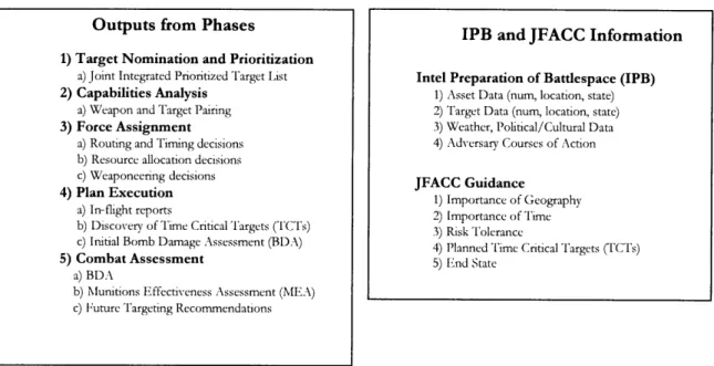
Phases of the JASTC are shown in Figure 2-2. Solid arrows represent the output from phases (which are inputs into subsequent phases) and hashed arrows represent thecoordination/guidance necessary to complete the phase. Coordination and guidance come
from either the JFACC or the intelligence analysts that are in charge of the Intelligence
Preparation of the Battlespace (IPB). The IPB is an estimate about the state of every entity and area on the battlefield at the current time. Information flows of the JASTC are listed in Figure 2-3. I-r I ~-.---_ J I |- .-
1Functional Output - -- Coordination/UpdatesOutputs from Phases
1) Target Nomination and Prioritization
a) Joint Integrated Prioritized Target List
2) Capabilities Analysis
a) Weapon and Target Pairing
3) Force Assignment
a) Routing and Timing decisions b) Resource allocation decisions c) Weaponeering decisions
4) Plan Execution
a) In-flight reports
b) Discovery of Time Critical Targets (TCTs) c) Initial Bomb Damage Assessment (BDA)
5) Combat Assessment
a) BDA
b) Munitions Effectiveness Assessment (MEA) c) Future Targeting Recommendations
Figure 2-3: Information Flows in the JASTC
The JASTC is a direct application of the Joint Targeting Cycle. The information flows are not discussed in detail here, although seeing a visual representation of where they fit into the JASTC is useful as they are fundamental to the functional model of Chapter 3.
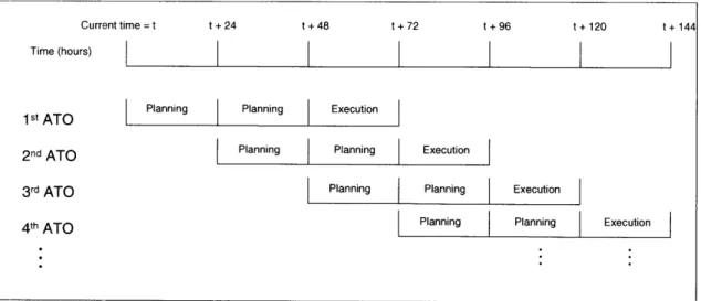
The main emphasis of the JASTC is the production of Air Tasking Orders
(ATOs). ATOs are generated on a recurring, 72-hour basis and fit into phases 2), 3) and4) of the JASTC. ATOs encompass all tasking of resources to missions involving planned
targets. The evolution of an ATO from start to finish involves 48 hours of planning and24 hours of execution. Also, a new ATO is started every 24 hours. Thus, at any given
time (after reaching "steady state"), there are two ATOs in the planning phase and one in the execution phase, as seen in Figure 2-4.
Although the ATO process is currently on a 72-hour schedule, this could decrease significantly in the next 20-30 years. As ISR assets become more proficient and information and data gathering capability increases, it makes sense for the ATO to shift to a shorter cycle. This gives the commander a chance to update and change the
objectives for different campaign phases throughout the day. It also allows more updated
versions of IPB to be factored into the plan. For these reasons we hypothesize that future ATOs will be on cycles in the range of 30 minutes to two hours.IPB and JFACC Information
Intel Preparation of Battlespace (IPB)
1) Asset Data (num, location, state) 2) Target Data (num, location, state) 3) Weather, Political/Cultural Data 4) Adversary Courses of Action
JFACC Guidance
1) Importance of Geography 2) Importance of Time 3) Risk Tolerance
4) Planned Time Critical Targets (TCTs) 5) End State
-An ATO requires numerous decisions to be made about each mission including,
but not limited to, the following:
1. What actions to take against each target
2. What; resources to use against which targets
3. When to start each mission and when to take the prescribed actions against
each targets
4. What resources to use to search in Areas of Interest for new targets
5. What routing to use to rendezvous, get to and from the target, etc.
Figure 2-4.' ATO cycle
It is worth noting that different divisions within the JAOC control the ATO at different times. In the planning phase, the Combat Plans division of the JAOC is in charge of ATO production. Once the ATO shifts into execution, the Combat Operations division takes over and is responsible for execution and monitoring. In this phase, new information such as in-flight reports, time-sensitive target discovery, and initial BDA might cause the
re-tasking of already assigned forces to adapt to the changing environment. Also, part of
producing and updating an ATO involves continually analyzing the IPB. ATO planners,
using this IPB information, seek to produce the plan that will most closely follow thecommander's stated guidance and objectives. In our scenario, we assume these objectives
Current time = t t + 24 t + 48 t + 72 t + 96 t + 120 t + 144 Time (hours) I I I
1 st ATO Planning Planning | Execution
2nd ATO | Planning Planning Execution
3rd ATO Planning Planning Execution
4th ATO | Planning Planning Execution
include maximizing total enemy destruction and minimizing attrition, operating cost, and
time until completion.
2.3.2 Coordination between AOCs and AOC Divisions
Even though we assume the JFACC has tactical control over both air and space operations, it is possible that the tasking of air and space resources could come from
different sub-organizations residing in separate physical locations. In present-day
operations, there exists a Space AOC at Vandenberg AFB, CA, that is separate from any JAOC and from which space tasking would originate in an overseas campaign. Given the vast amounts of satellites the US controls along with the numerous mission functions (ISR, communications, navigation, etc.), it is reasonable to assume that future Space AOCs and JAOCs will not be merged. Thus, for the ATO process to be effective, careful attention needs to be paid to coordination between the JAOC and the Space AOC, as wellas between the different divisions within AOCs.
In an interview with Lt Col Scott Henderson, a former Space Squadron Commander, details were provided on the nature of how space ISR currently supports and is coordinated with air operations [10]. Nominally, air planners submit imaging and signals intelligence requests to a central tasking board based on current or projected ATO
objectives. At least in the case of non-intelligence data such as space-based missile
warning or navigation data, requests are made through the Space AOC. The Space AOC then assigns priority levels to the requests depending on the nature of what is requested.ISR missions consisting of Target Identification (ID) or Battle Damage Assessment
(BDA) to coincide with a future projected strike time is possible if called for early
enough in advance. Currently, the highest priority targets (TSTs) can be imaged within a couple of hours of the request. Lower-priority targets might take up to a couple of days. Whether these times will be improved in the near future remains unclear. However, one thing is certain. The speed with which satellite ISR requests are fulfilled is critical to the successful coordination of air and space operations.Since neither the microsat nor the ORS system is currently operational in the military, it is difficult to know just how or what information needs to be shared between
these planners. It is likely, though, that different divisions within the JAOC will be in
charge of tasking (or providing requests for) different resource types. We may assume
there are separate divisions for aircraft tasking, ORS tasking, and satellite ISR requests.
Each division is in charge of formulating its own part of the ATO. One way to ensure divisional plans do not overlap is to partition the target set among divisions where each division is fully in charge of one group of targets. Another way, which might lead tomore effectively achieving the commander's objectives, is to coordinate the processing of
all targets among resources. Coordination involves the JFACC tasking JAOC divisions in
a collaborative manner, and with feedback. In a coordinated system, each division produces plans that help to further not only division goals, but the joint goals as well. Oneexample of effective coordination could be a microsat doing the initial ID of a target, an
ORS CAV striking the target, and aircraft performing the BDA, all in close succession.There are two direct benefits from the coordination of air and space operations.
These include 1) increased destruction capability gained from resource pooling, and 2)
increased efficiency due to a quicker flow of information. Here, increased efficiency is
defined as achieving desired results at a faster rate and at a lower cost. The measurableaspects of these benefits include 1) higher overall target destruction, 2) faster rate of
target destruction, 3) fewer aircraft attritions, and 4) lower resource operating costs.
2.4 Problem Statement
The Air and Space Operations Planning Problem (ASOPP) is defined as the problem of
assigning air and space resources in a coordinated fashion to find, identify, strike, and
assess the damage of enemy targets in such a way as to maximize the total enemy
destruction while minimizing attrition, operating cost, and time until completion. The
goals of this research are to:1. Define and model the higher-level, planning aspects of the ATO
2. Quantify the benefit of adding space operations to the ATO
3. Formulate effective coordination heuristics
4. Quantify the potential benefit of coordination within air and space
operations.
3 Model Development
In a mathematical model there is an inherent tradeoff between fidelity and computational
efficiency. Given all the different types of resources described in Chapter 2 plus the
numerous decisions required for each resource at each time step, a high-fidelity model of
the JASTC could become intractable for even small data instances. Instead, we focus on
producing a model that can generate high-level plans quickly, while allowing sublevelplanners to handle detailed decisions like aircraft routing. Modeling assumptions are
listed to lay the groundwork for a mathematical model of ASOPP. A hierarchical decisionstructure is proposed along with a system-level overview of functional components.
Finally, the inputs, decisions, and constraints at each level of decision-making are described in depth.3.1 Modeling Assumptions
In order to create a problem framework under which a viable solution method can be
found, certain assumptions involving the problem's mathematical structure are made.
While the validity of some assumptions could be questioned, they are necessary for
starting with a simple, if not completely realistic, model. Proceeding with this method
will leave room for more complex versions later and may give valuable insights into the real-world system. It is also an approach to obtaining approximate solutions to anotherwise intractable model. Six assumptions are listed below with descriptions and
examples as necessary. It is important to remember that these assumptions are for thepurpose of simplifying the construction of a solution method, not the computer
simulation.
Finite State and Discrete Attributes: The state of every object in the system
must be fully characterized by a finite number of attributes. For instance, there are three
attributes - target type, target location, and target damage status - that define the state of
the target. This is the finite state part of the assumption. The discrete attributes part, on the other hand, requires the value of each attribute to belong to a specified discrete set. In other words, for any target i, and any attribute a, the set of possible values that theattribute can take on, labeled S
i,must have a finite number of elements, Sia <o.
Consider a target, labeled tgtl, whose state is partly characterized by the target's latitude. In the real world, tgtl's latitude could take on any one of an infinite number of values
within the borders of the battlespace, whereas in the model, this assumption confines
latitude to be in Stgtl,LATDiscrete-Time Markovian System Evolution: The state of the system is only
allowed to change in discrete time increments. Any object in the system, therefore, can
only transition states at a time period, t T, where T is the set of time periods in the
battle campaign. Each action that is tasked by the model will commence at one of these
time periods. Moreover, state transitions must be independent of past state information;
each transition at time t + 1 can only depend on the current state, s,, and the actions, ,ttaken at time t [27]. This is known as the Markovian property and is written:
Consider the location of an enemy tank. The model, under this assumption, assumes that any future location of the tank depends only on where it is now, not on where it has been
previously.
Imperfect Target State Information: The attributes of enemy targets are
characterized with probability distributions. In a battlespace environment, uncertainty
abounds as to the enemy's location, capability, and intentions, so there is much value to be gained from "good" intelligence. To capture this in a model, the idea of imperfect
target state information is introduced. Knowledge of a target attribute for any particular
time is reflected in a prior distribution. Each new piece of information is incorporated
through a Bayesian update, which produces a posterior distribution (See [8] for
information on Bayesian statistics). This type of uncertainty is referred to as estimation
uncertainty. In the real world, once a target is observed by an ISR asset, more confidence
is gained about its location, damage status, speed, etc. The equivalent in the model is this:
An observation of a target causes the distribution mean of each target attribute to
improve, reflecting better accuracy. Moreover, the variance of each distribution
decreases, reflecting better precision. Finally, in addition to state estimation uncertainty
there is the uncertainty that comes from the simulation - whether a mission succeeds, whether an aircraft gets shot down, etc. It should be noted that the attributes of friendly resources are assumed to be known with perfect certainty.Target State Independence: The attributes of each target are independent of the
attributes of any other target. For instance, the fact that target a just got destroyed
should have no effect on the capability of target b. This is not a particularly realistic
assumption; there would be obvious effects on the capability of certain targets if a major
command and control facility was destroyed. Likewise, consider an enemy airbase
runway that is listed as a target. The ability of aircraft to take off and land at this airbase should be highly dependent on the damage state of the runway. In order for this assumption not to cause unrealistic results, careful attention must be taken to modeltargets without too many interdependencies.
Value and Constraint Proportionality: Any feasible action can only contribute
to the value of the objective function in a manner that is proportional with the level of
proportionality assumption prohibits an expression such as 3 x from entering the
objective function. Though an expression with a square root could help capture a
decreasing-marginal-returns effect from striking the same target multiple times, a
proportional objective function is assumed for now. The constraints of the problem are
also limited by proportionality in the same way.Value Additivity: The contribution to the objective function of any combination
of actions is the sum of individual contributions. If the expected value for action a is 3,
and the expected value for action b is 4, then the expected value for doing both a and b must be 7. An evident result of invoking this assumption is the inability to model
synergistic effects of combining resources, a common characteristic of battlefield
operations.
Now that the major modeling assumptions have been listed, a functional model of
ASOPP is presented, along with inputs and outputs at each level.
3.2 Functional System
At least two methods exist that future military leaders may use to partition
decision-making within a JAOC. The first way is according to resource function. Thismeans one director would control missions involving the ISR function and one director
would control missions involving the strike function. The directors would coordinate
when functions interact. The second way, which is the method used in this thesis, isaccording to resource category. In essence, category partitioning means separate directors
would control satellites, aircraft, and ORS assets, no matter the function of different
resources. Although it is not clear which method will prevail in the future, one attractivefeature of category partitioning is that resources never overlap; the control of a single
resource on a mission resides with one director. Alternatively, in a function partitioning,
the control of a single resource is split if there are aircraft that perform both ISR and strike.3.2.1 Functional Architecture
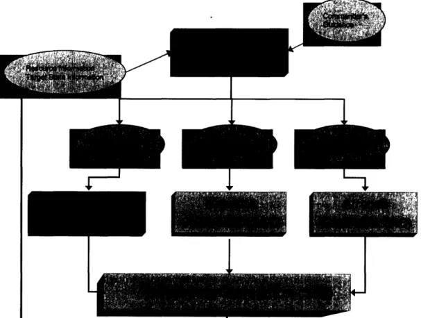
Figure 3-1 shows the functional architecture and is labeled the Functional
Coordinated Air and Space Operations System (FCASOS). There are five major
components to FCASOS: a top level coordination controller (CC), three sub-controllers, and a battlefield simulation (SIM). For the purposes of this research, a controller (to include the term sub-controller) is defined as an entity whose job it is to monitor battlespace information and task or re-task resources when new information becomes available. The resources of CC are the three controllers; the resources of the sub-controllers are the aircraft, satellites, and ORS assets. The frequency with which controllers are updated with new information is discussed in section 3.2.2.
I
I I
I
I
Figure 3-1: Functional Coordinated Air and Space Operations System (FCASOS)
The SIM in FCASOS is used to simulate, and evaluate the success of, controller-generated plans. The three sub-controllers include an aircraft controller (AC), a satellite
-I I I I I I I
controller (SATC), and an ORS controller (ORSC). The choice to use this type of
structure is somewhat motivated by its hierarchical nature, which closely parallels thedecision structure found in the military. Often, high-level commanders will make broad
goals to direct the general path of the unit, while leaving the specifics to lower levels. In the CONOPS given in Chapter 2, the JFACC is in charge of all air and space resources. Here, the JFACC is modeled as the top-level commander, or CC. The hierarchicaldecision structure, then, involves CC producing high-level plans that serve as the inputs
into sub-controllers. The three sub-controllers are in charge of resource tasking, and seek to assign their resources to targets in a manner that achieves the goals set forth by CC.ORSC plans the launching and payload release of all operationally responsive spacelift resources (as outlined in section 1.2.2). SATC decides which satellites should look at which targets at what times. AC directs all aircraft in the campaign to look for and destroy the maximum number of targets on the battlefield. The SIM, then, takes the
tasking from each sub-controller and simulates execution of these tasks in a given
battlespace environment. In Figure 3-1, rectangles represent functional components and
ellipses represent information flows. Red items represent models and software developed
in this research (CC and ORSC), while blue items represent pre-existing software components. CC and ORSC are discussed at length in sections 3.3 and 3.4 respectively.An overview of the pre-existing AC, SATC, and SIM, is given in section 3.5. First
though, it is important to understand system-level dynamics and how and when thefunctional components interact.
3.2.2 Planning and Re-Planning
In Chapter 2, the production of ATOs was highlighted, to include how new ATOs are generated on a 24 hour cycle. The reason that a single ATO cannot handle the planning
for the whole campaign is because of the enormous amount of uncertainty inherent in
battlefield operations. New targets emerge, old targets change location, strike missions
fail to completely destroy their intended targets, and ISR missions return information that updates the IPB. To account for this uncertainty, strategic objectives, operational plans, and tactical missions must be updated on a frequent basis.Define a replan as the output produced by one iteration of CC and one iteration of each of the sub-controllers. A replan involves one cycle through the functional system, starting with CC and ending with the SIM, and it completely updates the tasking of all resources in the battlespace. In air operations, there are three ways of determining how often to generate a replan. The first is to set a fixed interval of time such that new replans are generated after the specified time has passed from the previous one. The second way is to generate a replan only after a predefined event, such as a new high-value target appearing in the IPB. The third is a combination of the previous two, where replans are generated at the end of fixed intervals or after a predefined event, whichever comes first. We take the first approach - to re-plan at fixed intervals. It should be noted though that while the length of the replan interval is fixed for each SIM run, it may be changed from one run to the next. We define a SIM run as one complete battle campaign from start to finish.
In addition to deciding how often to replan, there is the issue of deciding for how long to plan. This is known as the planning horizon. The planning horizon is assumed to be for a length of time equal to or greater than the time of the next replan. Here, the concept of a rolling plan horizon is employed. At every replan, the piece of the previous plan that has yet to be implemented is cut off and a new plan is generated in its place. The main advantage of this approach is that it allows controllers to plan for the duration of the re-plan interval while taking into account the fact that the campaign keeps on going after the interval is over. This causes a smoother flow of resource assignment; there will be no surges in target assignments at the end of a replan interval in order to hastily gain leftover target value.
At the start of every replan, the SIM sends information to CC to provide an update of the state of the battle campaign. CC must determine how best to use resources over the planning horizon. It is this function of CC that is discussed next.
3.3 The Coordination Controller
It is the job of CC to manage the direction of the campaign through the collaborative
tasking of sub-controllers. It is difficult to quantify what is meant by the term
"collaborative." Instead of having one definition, we use the idea of differing levels of
collaboration (or coordination), where a level is taken to mean a combination of 1) theamount of knowledge of sub-controller capability that is used by CC to make decisions,
2) the degree to which sub-controller decisions (or expected decisions) influence theplans of other sub-controllers, and 3) the degree to which joint objectives and constraints
influence sub-controller plans. One extreme is no coordination, where CC merely passes sub-controllers whatever information is received from the SIM at each replan. The other extreme - complete coordination - is difficult to define and is not explored in this thesis.However, in a "highly" coordinated system, CC has knowledge of most sub-controller
capability and can make decisions that effectively integrate those capabilities. We
hypothesize that higher levels of coordination will produce increased target damages in
shorter amounts of time and at a lower costs. The following sections further define what
we term a "high" level of coordination by presenting the inputs, decisions, objectives, and
constraints of CC.
3.3.1 CC Inputs
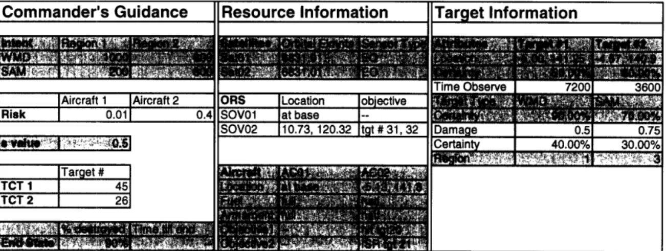
The inputs to CC come from the SIM and from user-specified parameters. Inputs can be broken up into three types:
1. Commander's Guidance
2. Resource Information
3. Target Information.
While CC receives updates to various parts of commander's guidance at different times,
the resource and target state information is updated once at the beginning of every replan. Example inputs into CC are presented in Table 3-1. We devote a section to each of the three input types.Commander's Guidance Resource Information Tar et Information
Table 3-1: Sample Inputs into CC
Commander's Guidance: In commander's guidance, the user is able to quantify
military objectives for the campaign. Five components to commander's guidance are
examined bellow. Commander's intent, which is the first component, is provided at the start of every campaign phase and is given in the form of a numerical measure for everyregion of the battlefield. It measures the relative importance of destroying targets of
different types and within different regions. Developing a good method of scaling andquantifying intent is a difficult problem not addressed here. We assume an acceptable
scale has been found and appropriate values have been given exogenously. These intent values are seen as independent from one another in the sense that they only measure atarget's worth in-an-of-itself, not how that target might contribute to other military
objectives. For example, on a scale of 1-1000, a WMD factory (WMD) in a particular region might have an intent value of 1000 while a SAM site (SAM) in the same region might have an intent value of 200. In essence, this means with the option of destroying five SAMs or one WMD, CC is indifferent about the decision. If there is an entity whose destruction would hinder campaign objectives, then its intent should be a negative value.The second component in commander's guidance is the acceptable risk level to aircraft, given by aircraft type, and in the range [0,1]. This is a measure of the maximum
![Figure 1-1: Target Categories (adaptedfrom [14])](https://thumb-eu.123doks.com/thumbv2/123doknet/14491540.525939/16.924.187.732.300.659/figure-target-categories-adaptedfrom.webp)