Current-based Force Input / Output Control for Novel Haptic
Interaction using the inFORCE Shape Display
by
Zhiyao (John) Ma
B.S., Massachusetts Institute of Technology (2017)
Submitted to the
Department of Electrical Engineering and Computer Science in Partial Fulfillment of the Requirements for the Degree of
Master of Engineering in Electrical Engineering and Computer Science at the
MASSACHUSETTS INSTITUTE OF TECHNOLOGY June 2018
© 2018 Zhiyao Ma. All rights reserved.
The author hereby grants to M.I.T. permission to reproduce and to distribute publicly paper and electronic copies of this thesis document in whole and in part in any medium
now known or hereafter created.
Author:
Department of Electrical Engineering and Computer Science May 25, 2018
Certified by:
Hiroshi Ishii, Jerome B. Wiesner Professor of Media Arts and Sciences Thesis Supervisor May 25, 2018
Accepted by:
Katrina LaCurts, Chair, Master of Engineering Thesis
2
Current-based Force Input and Output Control for Novel Haptic
Interaction using the inFORCE Shape Display
by
Zhiyao (John) Ma
Submitted to the Department of Electrical Engineering and Computer Science on May 25, 2018, in Partial Fulfillment of the Requirements for the Degree of
Master of Engineering in Electrical Engineering and Computer Science
A bstract
Shape changing interfaces have been become influential in the field of human-computer interaction. Their purpose is to give digital data a physical and tangible form, allowing for richer depths of interaction. However, though shape changing interfaces have
generally been excellent in allowing digital data to take a tangible form, they have yet been unable to simulate many sorts of higher dimensions of the data.
We propose inFORCE as an extension upon current generation shape displays. inFORCE is a force-responsive shape display with the ability for force input and output. This force-responsive capability opens up novel and exciting methods of haptic
interaction.
We developed a current-based force-sensing method using inFORCE without the use of force sensors. With this, we develop various applications of the inFORCE system, including object materiality emulation, multi-dimensional data representation, musical instrument simulation, and more. Lastly, we provide a framework for the flexible development of new applications using the inFORCE system.
Thesis Supervisor: Hiroshi Ishii
3
Table of C ontents
1 Introduction ... 6
2 Related Work ... 9
2.1 Haptic Interfaces ... 9
2.2 Shape Changing Interfaces ... 9
3 Hardware Design and Implementation ... 11
4 Software Design and Implementation ... 14
4.1 System Overview ... 14 4.2 Motor Controllers ... 15 4.3 Arduino ...16 4.4 openFrameworks...17 4.4.1 Application Control ...18 4.4.2 Running Applications ...18 4.4.3 Application Visualizations ...20 5 Force Detection ... 21
5.1 Current as a Force Approximation ... 21
5.2 Adjusting for Friction ... 22
5.3 Adjusting for Magnetic Patterns ...24
5.4 Force Estimation ...27
5.5 Calibration Process ...28
5.5.1 Calibrating for Friction ...28
5.5.2 Calibrating for Magnetic ...28
6 Applications ...29
6.1 Material Emulation Application ...29
6.1.1 Overview ...29
6.1.2 Applications in the Real-World ... 30
6.1.3 Implementation ... 31
6.2 Materiality Scanning Application ... 33
6.2.1 Overview ... 33
4
6.2.3 Implementation ... 35
6.3 Layered Data Application ... 36
6.3.1 Overview ... 36
6.3.2 Applications in the Real-World ... 37
6.3.3 Implementation ... 37
6.4 Piano Simulation Application ... 38
6.4.1 Overview ... 38
6.4.2 Applications in the Real-World ... 38
6.4.3 Implementation ... 39
6.5 Mirror Application ...40
6.5.1 Overview ...40
6.5.2 Applications in the Real-World ...40
6.5.3 Implementation ... 41
7 User Studies ...42
7.1 Procedure and Participants ... 43
7.2 Results and Discussion ...44
8 Future Applications of inFORCE ...48
8.1 Geological Data Representation ...48
8.2 Biomedical Data Representation ...49
8.3 CAD Interface ...50 8.4 Body Adaptation ... 51 8.5 Musical Instruments ... 51 9 Conclusion ... 53 10 Acknowledgements ... 53 11 References...54
5
List of Figures
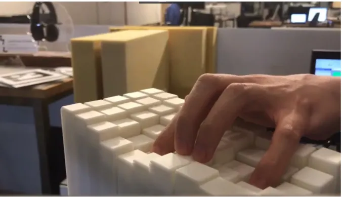
Figure 1. The inFORCE shape display replicating a foam-like material. ... 7
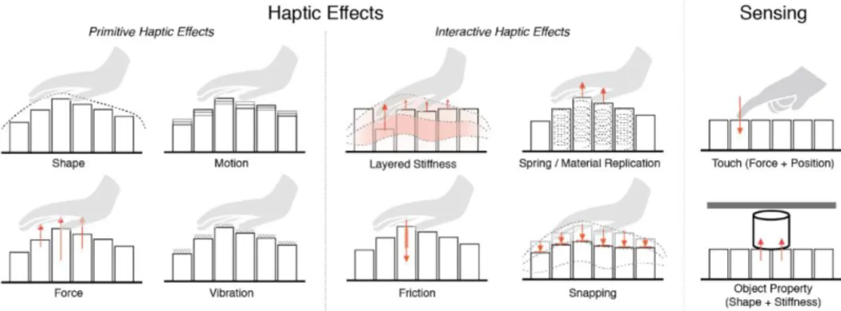
Figure 2. Various haptic effects possible with inFORCE ... 8
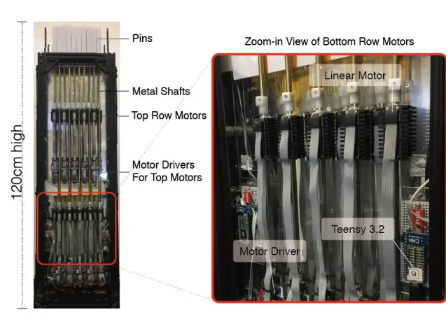
Figure 3. Hardware components. ... 11
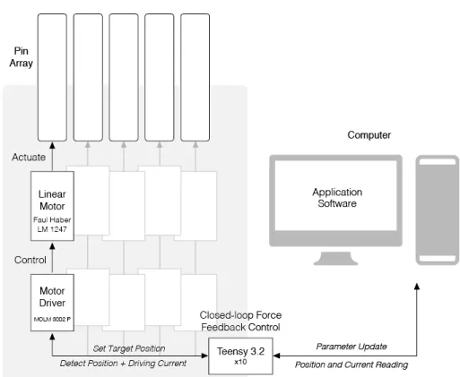
Figure 4. System Overview ... 14
Figure 5. Sample visualization from one of our applications. ...20
Figure 6. Graph of height vs scanned force. ... 22
Figure 7. Periodic magnetic pattern within the motor shaft. ...24
Figure 8. Oscillations due to the magnetic pattern. ...25
Figure 9. Periodogram showing the dominant frequencies of the oscillations. ...26
Figure 10. Raw current signal vs filtered signal of the current. ...27
Figure 11. Material simulation showing object deformation. ...29
Figure 12. Foam pads of varying stiffnesses and scanned stiffnesses of the foam pads. .. 33
Figure 13. Scanning and replication of shape, stiffness, and apperance. ... 34
Figure 14. Layered data app showing multiple layers ... 36
Figure 15. A piano simulation app in the layout of a piano keyboard. ... 38
Figure 16. Pin display bassed haptic filter with the same dimenions as inFORCE ...44
Figure 17. Results of stiffness magnitude response for digitally rendered stiffness ...45
Figure 18. Comparisons between rendered material data and actual material data ...45
Figure 19. Scatter graph of the multi-layer study of stiffness and thickness ...46
Figure 20. Geoscience data exploration showing different of the geosphere ...48
6
1 Introduction
Shape changing interfaces have been recently become influential in the field of human-computer interaction. Their purpose is to give digital data a physical and tangible form, allowing for richer depths of interaction. The practical applications of shape changing interfaces are numerous; in example, 3D object rendering, physical data representation, physical communication across distance, dynamic “furniture,” etc. However, though shape changing interfaces have generally been excellent in allowing digital data to take a tangible form, they have yet been unable to simulate many sorts of higher dimensions of the data.
As an example, take the simulation of a hand. While we can simulate the shape and size of the hand using current displays, we cannot simulate the stiffness of the fingernails, the softness of the fleshy areas, the flexibility and range of motion of the fingers, etc. We can simulate the shape of a mattress, but we cannot press down and feel its firmness, the way it indents, if it has memory, etc.
We propose inFORCE as an extension upon current generation shape displays. inFORCE is a force-responsive pin-based shape display that can detect forces being applied on it and provide variable force feedback. This force-responsive capability opens up novel and exciting methods of haptic interaction and demonstrates the ability for shape changing interfaces to simulate higher dimensionalities of data.
Contributions of this paper include:
• Development and implementation of a current-based force-sensing method without the use of force sensors.
• Development and implementation of various applications of the inFORCE system, including object materiality emulation, object materiality scanning, multi-dimensional data representation, musical instrument simulation, and more.
7
• Providing a framework for the flexible development of new applications using the inFORCE system.
• Proposition of an application space that outlines the capability of force-responsive shape displays in areas such as geoscience, biomedical exploration, body
adaptation, multi-material CAD interfaces, etc.
inFORCE is a project led by Ken Nakagaki, and the contents of this paper are mostly a result of our collaboration. My contribution specifically in the software side of inFORCE. The hardware was built by Daniel Fitzgerald, a recent Tangible Media Graduate, over the course of the past two years.
8
Figure 2 shows the various haptic effects possible with inFORCE using its force sensing
9
2 Related Work
2.1 Haptic Interfaces
Various types of haptic feedback devices that simulate the sensation of virtual objects have so far been explored [1]. Properties such as surface tension and heaviness have been reproduced through approaches such as Vibro-Tactile Feedback [2, 3] and
Electro-Stimulation [4, 5].
For kinetic compliance control, haptic devices have been made in various form factors, such as pen styluses [6], grasping gloves [7], and fingertip texture feedback [8]. Some of these works also can be used to explore volumetric data [9,10]. In our work, we use a shape changing interface for its ability to simulate without the need for the user to wear any additional peripherals.
2.2 Shape Changing Interfaces
As an evolution of Tangible User Interfaces [11] and Organic User Interfaces [12],
Actuated Interfaces have emerged in the field of HCI [13, 14, 15]. This realm of research aims to create interfaces that can control their shape and/or material properties in order to dynamically adapt to the user’s feedback and to represent information in real
physical 3D space. A recent paper [16] has noted that “future shape-changing interfaces should render haptic material properties in addition to shape alone.” This is one of the goals of the inFORCE project.
10
In order to provide dynamic stiffness control, jamming has often been used [17,18]. Haptic Jamming is a tangible display that aims to create dynamic shape and material property using an array of pneumatically actuated cells [19].
Pin-based shape displays have experienced recent popularity as a general platform of shape changing interfaces for prototyping a wide range of interactive applications, such as remote communication, dynamic affordances, and information visualization [20], with a range of technical variation, such as higher resolution displays, movable bases, and modular designs [21, 22]. Materiable aimed to emulate material properties through illusory haptic perception through touch and a physics simulation model [23]. While this method was visually effective, the integration of actual force control with precise force sensitivity is an open research area.
11
3 Hardware Design and Implementation
Figure 3. Hardware components.
inFORCE was designed and built by Daniel Fitzgerald, a recent graduate of the
Tangible Media Group. The overall system is comprised of the inFORCE shape display and a Windows CPU that running the software that controls the hardware. The shape display is comprised of a 10x5 array of pins, with each pin having dimensions of
19.2x19.2mm with a spacing between each pin of 0.8mm. The overall display size
(200x400mm) was chosen to be around the order of magnitude of a human hand, so that we could demonstrate haptic interaction—we hope to create larger surfaces in the
future.
To further illustrate some of the applications, we also included peripheral devices such as a projector for mapping images onto the display (Figure 14) and a USB camera
12
for capturing the appearance of scanned objects (Figure 12). Also, for ScannerApp (Section 6.2), we fabricated a scanner attachment counter board for the inFORCE system that can be easily placed on top the shape display, so that the pin display can push material to be scanned towards the counter board to capture compliance data (Figure 13).
The hardware of the inFORCE shape display contains ten Teensy 2.3
microcontrollers. Each microcontroller controls five motor drivers through CAN. Each motor driver controls a single linear actuator. We used “QUICKSHAFT Linear Actuator LM 1247 11 120” produced by Faulhaber for the motors, and “MCLM 300 P” motor drivers. As shown in Figure 3, motors for each row of pins were located on a single layer of panel. To densely pack the motors into each panel, five were placed at the top and five were placed at the bottom in a staggered fashion. Metal shafts were used to connect the motor shaft to the pins. Pins were made of a white photo-polymer fabricated with a commercial stereolithography 3D printer. The total weight of the pins for the motor to lift is 70g for the top row of motors and 95g for the bottom row of motors.
Each Teensy operates at 200Hz to communicate with the motor driver, and each motor driver as a control frequency of 400kHz.
QUICKSHAFT Linear Actuator
One of the core technologies incorporated into our implementation is the use of the high performance linear actuator called QUICKSHAFT by Faulhaber. The actuator is
composed of a 3-phase self-supporting coil together with three hall sensors to offer
micropositioning applications. The motor driver designed for QUICKSHAFT has its own PID control for position control when it receives commands through CAN from the Teensy microcontrollers, and sends back sensor data including position and current drawn.
13
From the actuator datasheet, the QUICKSHAFT motor is able to generate a continuous force of 3.6N and a peak force of 10.7N, with a maximum speed of 3.2m/s. Each motor runs with 28V, and the current drawn has a max capacity of 1.2A, up to 1680W for the 50 motors combined.
An improvement of inFORCE is that it has faster motion and force feedback compared to previous research-based shape displays, which facilitates the design of more precise haptic simulations. Through the motor driver, the system is able to extract position and driving current readings, which can be used to estimate the force being pressed as well as providing a target to hands/fingers.
14
4 Software Design and Implementation
4.1 System Overview
Figure 4. System Overview
The software implementation of inFORCE comprised of three main systems: 1) the openFrameworks software running on a Windows OS computer, 2) the Arduino code running in each of the 10 Teensy Arduino microcontrollers, and 3) the motor controllers, which each directly controlled the movement of one Faulhaber QUICKSHAFT motor. Each of the systems will be described in the following sections, starting with the lowest level.
15
4.2 Motor Controllers
Each of the 50 QUICKSHAFT motors is controlled by its own microcontroller. The microcontroller tells the motors where to go—more specifically, the microcontroller is in charge of the PID feedback loops that keep the motors in a certain position. Most of the software in the motor controllers was written by Faulhaber; our contribution to this system was in tuning the PID values. There were two main considerations we had to take into account when tuning the PID values.
We initially tuned the PID values to minimize the time it takes to get from the current position to a target position. This was done by having a high kP value and a suitably high kD value to damp it. However, we came across issues with this. When we tried making the pin move at a constant velocity, it resulted in a staircase-like
movement, because the pins were reaching the target position too fast. This was very noticeable on the haptic end—you could feel the pins vibrating. To fix this, we
decreased the kP value until the staircase smoothed out into a straight line.
The second issue was due to the difference in weights of the pins. In particular, there are two types of pins in the architecture of inFORCE: 25 long pins, and 25 short pins. This mass of each type of pin differs, and so we had to adjust the kP and kD values accordingly. In the end, we came up with two sets of kP/kD values that optimized the movement for each type of pin.
Changing the kP and kD values for all 50 motors was initially very time
consuming, as we had to plug in the motors one-by-one. We eventually came up with a method to change kP and kD values on the go, by passing a message from the
16
4.3 Arduino
The Arduino code resides in each of the 10 Teensy microcontrollers. We capped the Arduino software to run at 2000fps; higher is possible, but we found no need, as the bottleneck in the simulations occurred elsewhere. Each Teensy is responsible for
controlling its own 5 pins, and none others. The Arduino software is responsible for sending the target height to the microcontrollers, which then the microcontrollers move the motors accordingly. The microcontrollers send back the height and current values of each motor back to the Arduino software. Communication between the Arduino and the microcontrollers is done via CAN and happens at around 100fps.
Notably, without master coordination from the openFrameworks software, each Teensy only knows the position/current values of 5 pins. Thus, it would be impossible without a master coordinator to create simulations that have the pins working together, since each Arduino only knows the information about a small subset of the pins. This is why initially, all of the simulation software was written on the openFrameworks code, which coordinated the target heights of all 50 pins, sent the target heights to the
Arduino software, which then simply passed it onto the microcontrollers. However, this resulted in poor simulations, mostly because the communication delay between the Arduino and the openFrameworks was very high—up to 100ms round trip, which is very high for a haptic simulation, and because the openFrameworks software ran at a much slower 60fps.
Thus, we changed the simulations to work as follows. Each Arduino would still only get direct access to data about its own 5 pins; however, it would get information about the other 45 pins indirectly through the openFrameworks software (albeit delayed by around 100ms). This allowed for the simulations to run almost entirely on the
17
The simulations in the Arduino code are named Operations. Example Operations include a material simulation Operation, which simulates the shape, stiffness, and behavior of different types of materials; a piano Operation, which simulates the touch, feel and sound of a Steinway piano; and a mirror Operation, which mirrors the motion of pins on one side on the other side, and vice versa. The choice of Operation is specified by the openFrameworks code.
Simulations that do not require much accuracy, precision, or real-time feedback (for example, LayerApp, as discussed in Section 6.3) were developed and allowed to run on the openFrameworks software. The oF software would then send the target heights to an Operation called SimpleHeightOp, which would merely pass on that target height to the microcontroller.
Simulations that do require accuracy and speed, however, were developed entirely in Operations, which minimal involvement from the oF software, so as to get rid of as many of the delays as possible.
4.4 openFrameworks
The openFrameworks software runs on a Windows OS computer, and is coded in C++ using Visual Studio. The software runs in 60fps, much slower than the Arduino code— the effect and limitations of this framerate on our ability to render materiality will be discussed later in Section 6.1. The openFrameworks communicates indirectly with the motors through Arduino software, and is responsible for
• Application Control • Running Applications • Application Visualization
18
4.4.1 Application Control
An Application on the openFrameworks side is analogous to the Operation on the Arduino side. A given simulation can either run on the openFrameworks software (for non-performance critical simulations), or the Arduino software (for performance-critical simulations).
Applications include MaterialApp (Section 6.1), LayerApp (Section 6.3), PianoApp (Section 6.4) and MirrorApp (Section 6.5).
The oF software is responsible for choosing which Application to run at any particular time.
4.4.2 Running Applications
The control flow of Applications can go one of two ways.
If the simulation is running on the Arduino side (performance critical simulations):
On startup:
1) Application chooses which Operation the Arduinos should run. (For example, MaterialApp would choose to run MaterialOp, PianoApp would choose to run PianoOp)
Each frame:
1) Application receives height and force data from the Arduino for each of the 50 pins.
2) Application sends each Arduino the data for all 50 pins.
Thus, the Application here only acts as a way for the Operation to know the position/current of the pins it does not control.
19
If the simulation is running on the openFrameworks side (non-performance critical simulations):
On startup:
1) Application chooses SimpleHeightOp to run on the Arduino (SimpleHeightOp merely tells the motors to go to the height that the Application sends to it)
Each frame:
1) Application receives height and force data from the Arduino for each of the 50 pins.
2) Application calculates the new target positions of each of the 50 pins, depending on what type of simulation the Application is running.
3) Application sends each Arduino the new target positions for each of the 5 pins they control.
Thus, here, the Operation only acts as an intermediary between the Application the motor controller; all of the physics calculations are done on the openFrameworks side.
20
4.4.3 Application Visualizations
Figure 5. A sample visualization from one of our applications.
Visualization of the Application are done in openFrameworks. We give the option to toggle different visualizations on-and-off:
• 3D model of the board in its current state
• Graphs depicting the position and force on different pins • Force arrows depicting the current force on all the pins • Multicoloured layer visualizations
• Volumetric data visualizations
21
5 Force Detection
This section will discuss how the software is able to precisely detect the force acting on each pin. On a very high level, the current running through the motors is roughly proportional to the force acting on the pin. We will discuss why this is true, why the current is only an approximation of the force, and the transformations we did on top of the current to turn it into an accurate estimator of the force. We were able to
eventually detect the exact force acting on the pin up to an accuracy of roughly ±10g.
5.1 Current as a Force Approximation
We use the current running through the motors as our signal to estimate the force acting on the pins. The greater the force on the pin, the more current the motor has to use to oppose that force, in order to keep the pin at its target position. Current control is done within the motor controller function, which sets the current control using PID loops. The PID loop quickly converges to a steady state, which is the exact current needed to oppose the given force.
The motor controllers have a default maximum current limit and steady state current limit of roughly 1200 and 550 respectively. After extensive testing, we
determined that maximum and steady state current limits of 1650 and 900 were safe.
The current in the motor is extremely sensitive to changes in the net force acting on it. This results in an estimator with very high precision. We are able to detect
changes in the force of as little as a few grams.
In a perfect world, the current and force should satisfy a simple linear
relationship: 𝐂𝐮𝐫𝐫𝐞𝐧𝐭 = k1∗ 𝐅𝐨𝐫𝐜𝐞 + k0, where k1 and k0 are constants to be calibrated for, and differ between long and short pins. We would then be able apply a simple linear
22
transformation to the current in order to extract the force. However, in practice, there are two main confounding factors to this simple linear relationship: friction, and magnetic patterns within the motor. We thus rectify our equation as follows:
𝐂𝐮𝐫𝐫𝐞𝐧𝐭 = k2⋅ 𝐅𝐨𝐫𝐜𝐞 + 𝐅𝐫𝐢𝐜𝐭𝐢𝐨𝐧 + 𝐌𝐚𝐠𝐧𝐞𝐭𝐢𝐜 + k0 + ϵ (1)
where ϵ represents random noise. We thus have find good estimators for the Friction and Magnetic terms, and subtract them off to estimate Force. This will be discussed in the following sections.
5.2 Adjusting for Friction
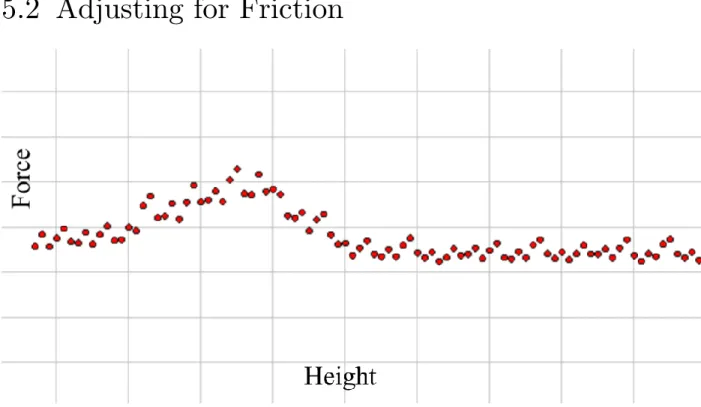
Figure 6. A graph of height (x-axis) vs scanned force (y-axis). The bump indicates the area with high amounts of friction.
23
Even though inFORCE was built precisely, and lubricated accordingly, there are still many moving parts, which inevitably leads to friction in the movement of the pin. This adversely affects the force estimation, because not only is the motor acting against the force being pressed on it, but also working against the frictional force. Therefore, without taking friction into account, we would tend to overestimate the force on the pin.
The frictional force 𝐅𝐫𝐢𝐜𝐭𝐢𝐨𝐧 behaves in the following way:
• 0 ≤ 𝐅𝐫𝐢𝐜𝐭𝐢𝐨𝐧 ≤ 300. That is, the frictional force tends to be between 0 and 300 mA, which is significant in comparison to our 1650 current limit
• 𝐅𝐫𝐢𝐜𝐭𝐢𝐨𝐧 = 0 if the pin is not in motion
• 𝐅𝐫𝐢𝐜𝐭𝐢𝐨𝐧 depends on the height that the pin is at. That is, the pin is subject to different amounts of friction at different heights
• 𝐅𝐫𝐢𝐜𝐭𝐢𝐨𝐧 differs between pins. That is, each pin is subject to different amounts of friction
• 𝐅𝐫𝐢𝐜𝐭𝐢𝐨𝐧 is a deterministic function, and is a function of only the three above parameters: if the pin is moving, height of pin, and which pin it is.
Since 𝐅𝐫𝐢𝐜𝐭𝐢𝐨𝐧 is a deterministic function, we modelled it as a 3-dimensional lookup table 𝐅𝐫𝐢𝐜𝐭𝐢𝐨𝐧(𝑖𝑠𝑀𝑜𝑣𝑖𝑛𝑔, ℎ𝑒𝑖𝑔ℎ𝑡, 𝑝𝑖𝑛𝐼𝑛𝑑𝑒𝑥).
• 𝑖𝑠𝑀𝑜𝑣𝑖𝑛𝑔 is either 0, meaning the pin is still, or 1 if the pin is moving • ℎ𝑒𝑖𝑔ℎ𝑡 is the height of the pin
• 𝑝𝑖𝑛𝐼𝑛𝑑𝑒𝑥 is the index of the pin, taking on one of 50 values
Optimally, ℎ𝑒𝑖𝑔ℎ𝑡 could take any value in [0,1,2, … ,100000}. However, we chose to round ℎ𝑒𝑖𝑔ℎ𝑡 down to the nearest 1000: thus, ℎ𝑒𝑖𝑔ℎ𝑡 ∈ {0,1000,2000, … ,99000,100000}, and used linear interpolation as an approximation. We did this in order to keep the lookup table manageable in size. The table comes out to 2 ⋅ 101 ⋅ 50 = 10100 values. We gathered these value through a calibration process.
24
5.3 Adjusting for Magnetic Patterns
This section will discuss the estimate of the 𝐌𝐚𝐠𝐧𝐞𝐭𝐢𝐜 term.
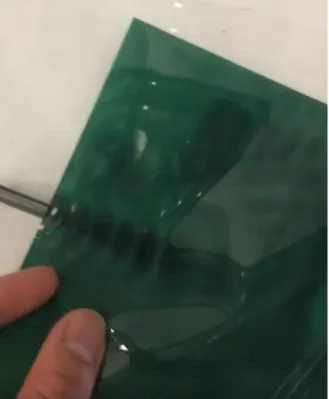
It turns out that there exists a periodic magnetic pattern within the motor that results in a periodic effect on the current.
Figure 7. We can see the periodic magnetic pattern within the motor shaft.
This periodic effect satisfies the following properties:
• 𝐌𝐚𝐠𝐧𝐞𝐭𝐢𝐜 is linearly proportional to the force on the pin: that is, 𝐌𝐚𝐠𝐧𝐞𝐭𝐢𝐜 = 𝑔(𝐅𝐨𝐫𝐜𝐞) ⋅ 𝐌𝐚𝐠𝐧𝐞𝐭𝐢𝐜̅̅̅̅̅̅̅̅̅̅̅̅̅, where 𝑔(𝐅𝐨𝐫𝐜𝐞) is a linear function 𝑔(x) = g1 ⋅ x + g0, and 𝐌𝐚𝐠𝐧𝐞𝐭𝐢𝐜̅̅̅̅̅̅̅̅̅̅̅̅̅ is not dependent on the force
25
• 𝐌𝐚𝐠𝐧𝐞𝐭𝐢𝐜̅̅̅̅̅̅̅̅̅̅̅̅̅ is dependent on the height of the pin, and exhibits a periodic pattern which occurs every 0.3cm, which coincides with the length of the magnetic pattern within the pin
• 𝐌𝐚𝐠𝐧𝐞𝐭𝐢𝐜̅̅̅̅̅̅̅̅̅̅̅̅̅ is different between pins
• 𝐌𝐚𝐠𝐧𝐞𝐭𝐢𝐜̅̅̅̅̅̅̅̅̅̅̅̅̅ is a deterministic function, and is a function of only the two above parameters: the height of pin, and which pin it is. In particular, it does not depend on if the pin is moving, in contrast with 𝐅𝐫𝐢𝐜𝐭𝐢𝐨𝐧
The function 𝑔(𝐅𝐨𝐫𝐜𝐞) = g1⋅ 𝐅𝐨𝐫𝐜𝐞 + g0 turns out to be fairly straightforward to
estimate, and is consistent between pins.
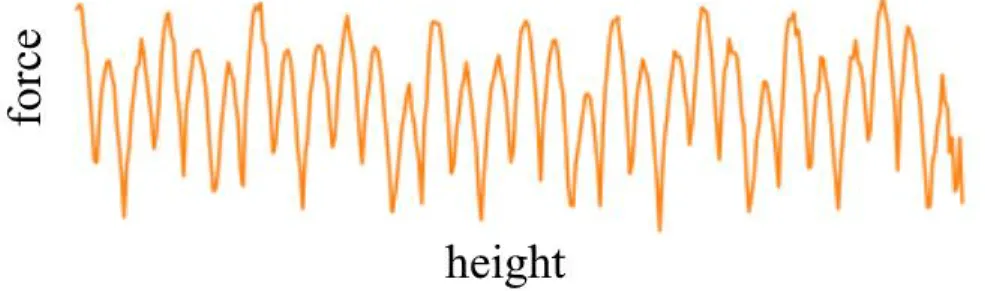
For a given pin, 𝐌𝐚𝐠𝐧𝐞𝐭𝐢𝐜̅̅̅̅̅̅̅̅̅̅̅̅̅ behaves like an almost sinusoidal wave as a function of the height.
Figure 8. The oscillations due to the magnetic pattern.
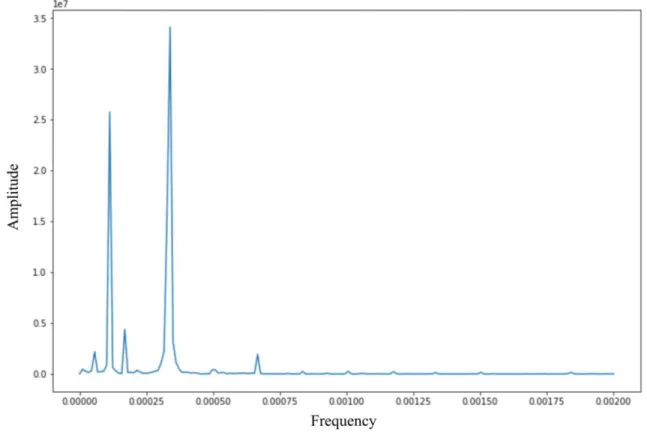
Doing a periodogram transformation shows the dominant frequencies to be at w0 = 0.00033, w1 = 0.00011 and w2 = 0.00016. This is consistent across pins. Notice that a 1
w0 = 3000, which corresponds to 0.3cm, which is the length or period of the
26
Figure 9. Periodogram showing the dominant frequencies of the oscillations.
Therefore, since the amplitudes of the dominant frequencies drops off
dramatically past the largest 3, it turns out that we can model 𝐌𝐚𝐠𝐧𝐞𝐭𝐢𝐜̅̅̅̅̅̅̅̅̅̅̅̅̅ to a high degree of accuracy with a function similar to a truncated Fourier series:
𝐌𝐚𝐠𝐧𝐞𝐭𝐢𝐜
̅̅̅̅̅̅̅̅̅̅̅̅̅ = A0⋅ sin(2πω0t + φ0) + A1⋅ sin(2πω1t + φ1) + A2⋅ sin(2πω2t + φ2)
In the above equation, the following are common across pins:
• A0, A1, A2, the amplitudes of the waves
• ω0, ω1, ω2, the frequencies of the waves, which satisfies ω0 = 3ω1 = 2ω2
The following differ across pins, and need to be calibrated for:
• φ0, φ1, φ2, the phases of the sine waves. These occur because the pins are actually slightly staggered at different heights with respect to the motors.
27
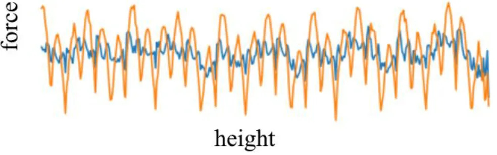
Our estimation of 𝐌𝐚𝐠𝐧𝐞𝐭𝐢𝐜 has an average correlation of 92% with the true value of 𝐌𝐚𝐠𝐧𝐞𝐭𝐢𝐜.
Figure 10. The orange line is the raw current signal; the blue is the filtered signal.
5.4 Force Estimation
Going back to Equation (1),
𝐂𝐮𝐫𝐫𝐞𝐧𝐭 = k2⋅ 𝐅𝐨𝐫𝐜𝐞 + 𝐅𝐫𝐢𝐜𝐭𝐢𝐨𝐧 + 𝐌𝐚𝐠𝐧𝐞𝐭𝐢𝐜 + k0 + ϵ (1)
We have that 𝐌𝐚𝐠𝐧𝐞𝐭𝐢𝐜 = 𝑔(𝐅𝐨𝐫𝐜𝐞) ⋅ 𝐌𝐚𝐠𝐧𝐞𝐭𝐢𝐜̅̅̅̅̅̅̅̅̅̅̅̅̅ = (g1⋅ 𝐅𝐨𝐫𝐜𝐞 + g0) ⋅ 𝐌𝐚𝐠𝐧𝐞𝐭𝐢𝐜̅̅̅̅̅̅̅̅̅̅̅̅̅. Thus,
𝐂𝐮𝐫𝐫𝐞𝐧𝐭 = k2⋅ 𝐅𝐨𝐫𝐜𝐞 + 𝐅𝐫𝐢𝐜𝐭𝐢𝐨𝐧 + (g1⋅ 𝐅𝐨𝐫𝐜𝐞 + g0) ⋅ 𝐌𝐚𝐠𝐧𝐞𝐭𝐢𝐜̅̅̅̅̅̅̅̅̅̅̅̅̅ + k0+ ϵ
Solving for 𝐅𝐨𝐫𝐜𝐞, we have
𝐅𝐨𝐫𝐜𝐞 =𝐂𝐮𝐫𝐫𝐞𝐧𝐭 − 𝐅𝐫𝐢𝐜𝐭𝐢𝐨𝐧 − g0⋅ 𝐌𝐚𝐠𝐧𝐞𝐭𝐢𝐜̅̅̅̅̅̅̅̅̅̅̅̅̅ − k0− ϵ k2+ g1⋅ 𝐌𝐚𝐠𝐧𝐞𝐭𝐢𝐜̅̅̅̅̅̅̅̅̅̅̅̅̅
Therefore, a consistent estimate of 𝐅𝐨𝐫𝐜𝐞 is given by
𝐅𝐨𝐫𝐜𝐞̂ =𝐂𝐮𝐫𝐫𝐞𝐧𝐭 − 𝐅𝐫𝐢𝐜𝐭𝐢𝐨𝐧 − g0⋅ 𝐌𝐚𝐠𝐧𝐞𝐭𝐢𝐜̅̅̅̅̅̅̅̅̅̅̅̅̅ − k0 k2+ g1⋅ 𝐌𝐚𝐠𝐧𝐞𝐭𝐢𝐜̅̅̅̅̅̅̅̅̅̅̅̅̅
28
5.5 Calibration Process
Here, we briefly describe the calibration process.
5.5.1 Calibrating for Friction
Run CalibrationApp, a software that moves the pins up and down and measures the friction. This will save a file with a name specified inside CalibrationApp. Inside
Application.cpp, change replace name of the old calibration file to the name of the saved file.
5.5.2 Calibrating for Magnetic
Run WeightCalibrationApp for each pin using 160g of weight on top. Save the name in
the format “WeightCalibrationData_<pinCol>x<pinRow>_160g.txt”. Put these files in
the same directory as WeightCalibrationParameterCalculation,py. Then, run
WeightCalibrationParameterCalculation,py, which will create the parameter file.
Copy the contents of this parameter file and the old value of the parameter
variable in PinModel.cpp with the contents of the parameter file. Remember to do this
29
6 Applications
We built a variety of applications in order to showcase the capabilities of inFORCE. All of these applications rely on inFORCE’s core functionalities:
• Position Control: each pin can be set to move to a certain position with extremely high speed and precision.
• Force Detection: each pin can detect the force acting on it in real-time with high precision.
6.1 Material Emulation Application
6.1.1 Overview
30
MaterialApp is an application designed to replicate the stiffness, shape, and behaviour of objects of different stiffnesses, viscosity, etc.
• Stiffness: how hard each pin feels when touched. This is dependent on the location of the pin and the height of the pin.
• Shape: the overall shape of the object.
• Behaviour: the behaviour of the object when interacted with.
As an example, MaterialApp could simulate the materiality of a foam mattress. The mattress would feel relatively soft, but the stiffness would increase as the user presses down. The shape of the mattress could be a rectangle, or it could mold to the user’s shape a la memory foam. The behaviour of the mattress would encompass a few features such as: when pressing down on a pin, how much the surrounding pins indent; the slow speed at which the mattress would rise after being indented.
As a second example, MaterialApp could simulate the materiality of a human hand. The bonier parts of the hand (knuckles, fingernails) would feel stiff. The fleshier areas would feel softer, but as the user presses down, the pins would feel hard to simulate the hitting of bone. The shape would obviously emulate the shape of the hand— however, since the resolution of the pin display is relatively large, this could be a zoomed in version.
6.1.2 Applications in the Real-World
Material object simulation has many possible applications in the real world, such as the following:
31
• Doctors could use MaterialApp to simulate the materiality and behaviour of a chest cavity. This could help, for example, nurses in the practice of CPR, to give haptic feedback on exactly how much to push down, and what they should expect to feel when performing chest compressions.
• Product designers can use MaterialApp to test the feel of a product before putting in the resources to actually manufacture it. This could speed up the design process and improve the speed of iteration cycles.
MaterialApp can be used to simulate various pieces of furniture, such as pillows, chairs, and mattresses. The stiffness and shape of the furniture can be changed
dynamically, and we can model innovative dynamic furniture that cannot be made using conventional methods; for example, a bed that slowly massages you as you fall asleep, or a pillow that wakes you up in the morning using a gentle vibration alarm.
6.1.3 Implementation
MaterialApp parameterizes a material using the following parameters:
• Height-dependent target force. For each pin, at each height, there is an associated “target force.” The higher the target force, the stiffer the material. • Max-height and min-height boundaries for each pin. These determine the
shape of the object.
• Indentation amount. This is a single number that determines how much the surrounding area indents when pressing down on a pin.
Given these parameters, MaterialApp is built as following: for a given pin,
• If the force on the pin is larger than the target force, the pin moves down; otherwise, the pin moves up. The speed of movement is controlled by a PID
32
loop that optimizes for the error between the force on the pin and the target force.
• Pressing down creates an indentation of a given size. Pins surrounding the given pin are moved down to the height of that indentation.
There were a few challenges involved in creating MaterialApp. Initially, the app was built in the openFrameworks software. The round trip latency from sending position control commands to the Arduino and back is around 100ms; in the realm of haptic perception, this is much too large. Furthermore, the framerate of the openFrameworks is only 60fps, which affected the responsiveness of the application. We remedied this by implementing MaterialApp in the Arduino software. This reduced the latency to roughly 20ms, and increased the framerate to 200fps. Each Arduino knew the positions of the other pins by communicated with the openFrameworks software, as described in Section 4.4.
33
6.2 Materiality Scanning Application
6.2.1 Overview
Figure 12. (Above) Four foam pads of varying stiffnesses. (Below) The scanned stiffnesses of the foam pads.
34
ScannerApp is an application that scans the shape and stiffness of objects for display in MaterialApp. ScannerApp is similar to as an image scanner, but instead of scanning images and printed text, it scans shape, stiffness, and materiality.
Figure 13. Scanning and replication of shape, stiffness, and apperance.
In order to use ScannerApp, the user places the object(s) to be scanned under the scanning lid. The application then performs the scanning algorithm, which scans shape and stiffness by slowly pressing against the object. The data is then parameterized, and saved for displaying in MaterialApp.
35
6.2.2 Applications in the Real-World
With ScannerApp, we can capture material properties of the objects around us. We can then simulate those objects without having to explicitly model their stiffness by hand.
For example, if a doctor wanted to simulate a hand, they can use MaterialApp to accurately scan the parameters of a hand. This also saves them the trouble of having to manually implement the shape and stiffness parameters themselves.
6.2.3 Implementation
ScannerApp parameterizes the material in the same way that MaterialApp does (Section 6.1). ScannerApp explicitly scans for these parameters as follows:
• First, the user holds the object against the scanning lid.
• The pins quickly move upwards until they feel significant amount of force, then slowly move downwards until they feel no force. This is essentially scanning the top shape of the object.
• The pins then slowly, in a staggered fashion, move upwards while scanning the force that they feel. We stagger the pins because the movement of one pin could affect the force felt by another pin.
The data is then gathered and stored in a .txt file, which can be plugged into MaterialApp for material simulation.
36
6.3 Layered Data Application
6.3.1 Overview
Figure 14. Layered data app showing multiple layers. Users can press down, and the pin display will successively snap down so that the users can explore each layer.
LayerApp is an application for displaying volumetric multi-dimensional data. LayerApp takes data that in the form of multiple layers, and allows the user to explore each layer and easily switch between them. To be more precise:
LayerApp takes in data in the form of multiple layers. Each layer associates each pin with a given height, and the layer as a whole forms a sort of 2D topographical landscape.
When the user presses down on the layer, it can snap to the next layer. Whether or not it snaps depends on the amount of for the user presses with.
37
On each given layer, the user can interact with the pins in different ways, such as pinpointing a location for later reference, or pressing down on individual pins to explore the data at that location.
6.3.2 Applications in the Real-World
LayerApp is a way to visualize and explore volumetric multi-dimensional data. For example, a geoscientist may want to explore geological layer data (Figure 14).
LayerApp could allow for visualizations of this data in different ways than they are traditionally used to (2D computer screens), and exploration in the form of haptic feedback. For example, the force required to change layers could be proportional to the stiffness of the rock at that layer.
6.3.3 Implementation
The application of LayerApp is similar to the MaterialApp (Section 6.1), but instead of continuous movement, the pins snap to each layer. LayerApp can be thought of as a discretized version of MaterialApp, and is implemented as such.
38
6.4 Piano Simulation Application
6.4.1 Overview
Figure 15. A piano simulation app in the layout of a piano keyboard, with white keys and black keys.
PianoApp is an application that simulates the touch, action, and sound of a piano. It simulates the keys from C4 to E5, including both white and black keys. The harder the user presses down on the keys, the more powerful the keys play, in a way similar to that of a real piano. The sound was modelled off of a Steinway grand piano.
6.4.2 Applications in the Real-World
PianoApp shows how we can replicate mechanical objects in inFORCE. In particular, not only can we replicate their shape, but we can replicate their precise behaviour when interacted with, for example, the action of the keys and the sounds that they make when pressed with a certain force and velocity.
39 Extensions of PianoApp could include:
• Dynamically changing the brand or model of the piano. For example, a user could compare the difference between a Steinway and a Schimmel
• Dynamically changing the type of instrument being played
We can generalize PianoApp beyond musical instruments to encompass the idea of simulating a wider range of mechanical objects. An example of how this could be useful is in product design. A researcher could have a model of a product, including how it behaves, and they may want to interact with it in real life. Instead of having to
fabricate the product, the research could feasibly simulate the product on the inFORCE system as a preliminary. This could speed up the time it takes to iterate through
different designs.
6.4.3 Implementation
Since PianoApp is a performance-critical application, and requires precise haptic feedback, the code was implemented in Arduino (see Section 4.4.2).
PianoApp consists of keys, consisting of 2-3 pins each, each of which move
together as a unit. The actual implementation of the movement of each key itself is also similar to that of MaterialApp (Section 6.1), with the parameters tuned to simulate the materiality of a key. The sound being played comes from the audio recording of a Steinway grand piano, and the volume of that sound is an increasing function of the velocity of the key when it hits the bottom.
40
6.5 Mirror Application
6.5.1 Overview
MirrorApp is an application that showcases the ability to physically interact with someone else over distance.
MirrorApp divides the display into two halves. When the user presses down on one half, the pins move down, while the pins on the other half move up an equal distance with the same amount of force. However, if another user presses on the other half while the first user is pressing on the first half, the net movement of the pins
depends on who is pushing harder. The users are essentially pushing against each other, using the pins as an intermediary to “transfer” the force. Therefore, we can think of MirrorApp as transmitting the shape of the user’s hand, along with the force that the hand is exerting. If the two halves were farther away (say, in different countries), we can imagine this as a way to physically interact with somebody or something else through the shape display.
6.5.2 Applications in the Real-World
MirrorApp showcases the potential of shape displays for physical communication across distance. In the future, with a high enough resolution pin display, we can imagine the ability for a person to physically interact with a person or object in a remote location, including being able to feel the object, push against the object, and have the object push back.
This could also be useful in remote robotic control scenarios. For example, we can imagine a surgeon performing surgery remotely using a high-definition shape display.
41
6.5.3 Implementation
MirrorApp’s implementation is a modification of MaterialApp’s code (Section 6.1). The differences are:
• The target force for each pin is equal to the force acting on the pin on the other side
• The indentation amount is set to zero
42
7 User Studies
In order to evaluate the haptic representation capability of the inFORCE system, we conducted three preliminary studies:
1. Compliance Stiffness. Our first study was conducted validate the stiffness
perception rating of our material replication algorithm. We replicated a variety of materials whose stiffness as a function of height varied in accordance with
Hooke’s law, Force = SpringConstant ⋅ PinHeight. SpringConstant was set to 1 of 8 different parameters that we chose beforehand. Each participant was queried twice for each emulated stiffness (16 trials total) and were asked to evaluate the perceived in their own scale.
2. Material Comparison. Our second study evaluated the haptic replication
capability of MaterialApp when using the data provided by ScannerApp (Section 6.1, 6.2). We used both the captured data and the actual material samples
presented in Figure 5. Participants were asked to compare the haptic perception of the rendered material on inFORCE with the actual material, and give a score as to how accurate they believed the representation to be (with 100 being
perfect). Since inFORCE is not capable of rendering the surface texture of
materials, we prepared a pin display-based haptic filter with the same dimensions as inFORCE which can be placed on top of material samples. This filter
replicates the compliance force while keeping the surface texture and structural functionality identical to inFORCE. Participants were asked to compare four sets of haptic exploration for four different materials (16 total) in a random order. For the pair they gave the highest score to, they were asked to describe why they felt it was close, and why it wasn’t perfect.
3. Multi-Layer. Our second study was conducted to evaluate the volumetric haptic effects distributed throughout multiple layers as users pressed the pins down (see
43
Section 6.3). In each layer, participants were asked to evaluate the perceived stiffness of the layer, in addition to the thickness of the layer, using their own scale. Participants rated a total of 20 layers of varying stiffnesses and thicknesses. The stiffness and thickness values were generated randomly each time, within a specific range.
Because the main purpose of all three studies were to evaluate the stiffness, volumetric and material property perception, we set the shape of the surface to be flat by default.
7.1 Procedure and Participants
For all three studies, users were asked to wear an eye mask to remove visual bias. They were told to use their dominant hand to press on the pins, and to communicate with the experimenters vocally. They were also advised to touch and press the pins in various ways (e.g. with finger tips vs with palms, or with different speeds and forces).
Participants (N=10, 5 female, 5 male), aged 18-32 (mean=23.78, SD=5.87 ) were recruited for the studies and received a 15 dollar gift card as compensation. Three studies were conducted in a row, which lasted 30-45 minutes total, including 3 minutes of break in-between. At the end of the study they were asked to fill in a short
44
Figure 16. Pin display bassed haptic filter with the same dimenions as inFORCE for use in the Material Comparison study. Materials in Figure 12 were placed below the figure
so that users could feel their compliance stiffness by pressing the pins.
7.2 Results and Discussion
Figures 17, 18, 19 show the results of the Compliance Stiffness, Material Comparison, and Multi-Layer studies respectively.
45
Figure 17. Results of stiffness magnitude response for digitally rendered stiffness with 8 levels of spring constant values. The error bars are one standard deviation.
Figure 18. Table of comparisons between the rendered material data and the actual material data. Values are the average closeness score ratings from all participants (with 100 being highest). Values in [...] represent standard deviation.
46
Figure 19. Scatter graph of the multi-layer study of stiffness and thickness. The trend line shows the tendency of response of each participant. Each colour represents a
different participant.
The results of the Compliance Stiffness and Multi-Layer studies show overall intended results, while the Material Comparison study had some unintended results. In this study, for Material #4, which was the most rigid material among others, people tended to answer the highest closeness score for the correct one. However, participants seemed to mix up the three simulations of softer material data, each saying that the replicated Materials 1-3 were most similar to Material 3. While material scanning is able to capture the linear increase in stiffness with respect to depth (as described by Hooke’s Law), our current simulations do not account for more complex material properties, such as elasticity, how fast the materials move back after compression. Some
participants reported that the biggest difference between the rendered material and actual material was the speed at which the material returned to its original shape. Some participants also reported oscillations when pins were pressed down deeply, due to suboptimal PID tuning. Because the softer materials were easier to press down deeply,
47
this could be a reason why Materials 1-2, the softest materials, had a low closeness score.
In the post-study survey, we asked the participants the following question: “How well were you able to feel the stiffness of the material for the following methods of touching? 1) Pressing with finger tips, 2) Pressing with palm.” This question was
answered on a scale from 1-5, with 5 meaning very good. The average scores were 3.5 for fingertips was 3.5 and 4.1 for palm. We assume that this is because the individual
QUICKSHAFT motors were not strong enough to withstand the force of a fingertip concentrated on one pin, while using palms spread the load to multiple pins. We believe that adding a mechanical clutch or brake to individual pins could be a solution for future improvement.
48
8 Future Applications of inFORCE
In this section, we describe various possible applications of inFORCE.
8.1 Geological Data Representation
Figure 20. Geoscience data exploration showing different of the geosphere (simulated data). Users can press in to touch and explore the different layers.
inFORCE is able to represent various types of multi-dimensional data, and allow its exploration in new and novel ways. One obvious choice is shape and volumetric material data, such as that present in geoscience data.
49
Geoscience data is commonly composed of multi-layered data with variable material properties in each layer. As an example, a geoscientist in the oil industry may need to explore higher dimensional geological data to find rigid slabs of rock in order to find areas with oil reserves. Traditionally, geoscientists view this data on screens as 2D cross-sectional cuts of such data—this type of flat data representation is naturally not suited to the higher dimensionality of the data they are exploring.
As the user presses into the pins, the rendered shape snaps to different layers of the seismic data. The amount of force required to snap can vary with each layer, such that the user can intuitively understand both the material properties and shape at each layer. Furthermore, at each layer, the user can under the data through touch using various haptic effects such as vibration.
8.2 Biomedical Data Representation
Figure 21. (a) A model of an arm. A doctor can press down on the soft flesh simulation
to feel a user's pulse. (b) A chest simulation for practicing CPR.
Another field in which inFORCE could be useful for data representation is the medical field, in which our device can be used to train palpation. When medical students train
50
for surgery or related fields, they frequently require the use of a cadaver; or if one is not available, they have to resort to using 2D screens, which lack haptic and tactile
sensation [24], or a static anatomical model of a human, which lacks the ability to dynamically respond to physical touch. While similar applications have been presented in the field of haptics and shape changing interfaces [23], inFORCE further provides the capability to render depth and force feedback without require the user to put on a wearable.
With our height dependent force feedback capability, we can simulate the shape,
stiffness, behavior of the human body with respect to an applied force; the user can then experience interactions on the human body. Some examples include:
• Haptic perception of tumours; the user feels the stiffness and shape of the tumour when pressing into specific depths
• Simulation of heart pulse when pressing in a specific amount on appropriate parts of the human body (neck, wrists, heart)
• Training nurses to perform CPR by pressing down on a simulated chest; the chest compressions have the stiffness and haptic feedback of compressions real chest, with accompanied visual, haptic, and perhaps audio (i.e. the sound of ribs breaking) feedback. The system can indicate if the nurse needs to compress harder or softer, or with more or less frequency and depth. (Figure 21b)
8.3 CAD Interface
As material fabrication and 3D printing rises in popularity in industrial and research facilities in recent years, CAD interfaces has given users the ability to design models in their desired shape and materiality. Utilizing our system, users can tangibly shape forms with their hands, “paint” material stiffnesses, and instantly check how the material
51
property feels through their hands. Furthermore, similar to how I/O Brush enabled the capturing of real-world color and pattern for digital drawing [30], or how KidCAD enabled the capturing of real-world shape for digital modelling [10], with our material scanning capabilities (Section 6.2), users can take real-world physical objects or materials and replicate that in their digital CAD model.
8.4 Body Adaptation
By using our scanning and material simulation capabilities, our system can capture key pieces of data about our body and use that provide appropriate comfort according to the captured data, for example in the form of a shape-changing pillow, or a large memory foam-like mattress that can dynamically adapt to your body type. This could be the future of furniture, where we could imagine objects like beds, pillows, or chairs that can dynamically adapt to our body depending our the situation (for example, responding to injury or pregnancy).
8.5 Musical Instruments
Playing a musical instrument is rife with haptic experiences; the touch of the keys, the feel of a vibrating drum. Our inFORCE system is able to replicate a variety of musical instruments, including their shape, haptic feeling, behavior, and sound when played.
For example, we were able to emulate the shape, behavior, sound, and touch of a piano keyboard (Figure 6.4). Our piano emulation responds to presses of different speed and force with a note of suitable volume, similar to how a real piano would behave. Our single device can render a wide variety of instruments, and give the realistic feeling of playing the rendered instrument. inFORCE also has the potential to emulate new
52
instruments, and physically switch between multiple modes for instant musical composition and live performance.
53
9 Conclusion
In this paper, we described how inFORCE’s force-responsive capabilities opens up numerous possibilities for novel forms of haptic interaction. We described how we can use the basic inFORCE (position control, precise force feedback, variable force control) can be used to create complex simulations, including accurate material simulation, mechanical object simulation, and rich 3D physical data representations.
In the process, we developed a way to transform value of the current running through the motors into an accurate estimator of the force on it. Using this, we were able to develop a variety of applications that showcase inFORCE’s potential as an evolution of current-generation shape displays. Lastly, we proposed various applications that can be further implemented both on inFORCE using the framework that we
developed and on future generation shape displays.
All-in-all, we believe that force interactivity in shape changing interfaces has the potential to greatly enrich the field of haptic technology in human-computer interaction.
10 Acknowledgements
Thank you Hiroshi Ishii for being a very awesome and amazing fun cool professor.
Thank Ken Nakagaki for being an amazingly kind, patient, caring, humble, intelligent,
and excellently well dressed advisor. Special thanks to Dan Levine for helping us with
parts of the pin calibration process, and thank you to Daniel Fitzgerald for building the
inFORCE system. And thank you to my most precious family-- Elisa, Yonghui, Anita
54
11 References
1. Vincent Hayward, Oliver R Astley, Manuel Cruz-Hernandez, Danny Grant, and Gabriel Robles-De-La-Torre. 2004. Haptic interfaces and devices. Sensor Review 24, 1 (2004), 16–29.
2. Yoichi Ochiai, Takayuki Hoshi, Jun Rekimoto, and Masaya Takasaki. 2014. Diminished haptics: Towards digital transformation of real world textures. In International Conference on Human Haptic Sensing and Touch Enabled Computer Applications. Springer, 409–417.
3. Allison M Okamura, Jack T Dennerlein, and Robert D Howe. 1998. Vibration feedback models for virtual environments. In Robotics and Automation, 1998. Proceedings. 1998 IEEE International Conference on, Vol. 1. IEEE, 674–679 4. Pedro Lopes, Sijing Young, Lung-pan Cheng, P Marwecki, and Patrick
Baudisch. 2017. Providing Haptics to Walls and Other Heavy Objects in Virtual Reality by Means of Electrical Muscle Stimulation. In Proc. Conf. Human Factors in Computing Systems (CHI).
5. Seiya Takei, Ryo Watanabe, Ryuta Okazaki, Taku Hachisu, and Hiroyuki Kajimoto. 2015. Presentation of Softness Using Film-Type Electro-Tactile Display and Pressure Distribution Measurement. In Haptic Interaction. Springer, 91–96.
6. Thomas H Massie, J Kenneth Salisbury, and others. 1994. The phantom haptic interface: A device for probing virtual objects. In Proceedings of the ASME winter annual meeting, symposium on haptic interfaces for virtual environment and teleoperator systems, Vol. 55. Citeseer, 295–300.
7. Mourad Bouzit, Grigore Burdea, George Popescu, and Rares Boian. 2002. The Rutgers Master II-new design force-feedback glove. IEEE/ASME Transactions on mechatronics 7, 2 (2002), 256–263.
55
8. Hrvoje Benko, Christian Holz, Mike Sinclair, and Eyal Ofek. 2016.
Normaltouch and texturetouch: High-fidelity 3d haptic shape rendering on handheld virtual reality controllers. In Proceedings of the 29th Annual Symposium on User Interface Software and Technology. ACM, 717–728. 9. Ricardo S Avila and Lisa M Sobierajski. 1996. A haptic interaction method
for volume visualization. In Visualization’96. Proceedings. IEEE, 197–204. 10. J Kenneth Salisbury Jr. 1999. Making graphics physically tangible. Commun.
ACM 42, 8 (1999), 74–81.
11. Hiroshi Ishii and Brygg Ullmer. 1997. Tangible bits. In Proceedings of the SIGCHI conference on Human factors in computing systems - CHI ’97. ACM Press, New York, New York, USA, 234–241. DOI:
http://dx.doi.org/10.1145/258549.258715
12. David Holman and Roel Vertegaal. 2008. Organic user interfaces: designing computers in any way, shape, or form. Commun. ACM 51, 6 (2008), 48–55. 13. Majken K. Rasmussen, Esben W. Pedersen, Marianne G. Petersen, and
Kasper Hornbæk. 2012. Shape-changing interfaces. In Proceedings of the 2012 ACM annual conference on Human Factors in Computing Systems - CHI ’12. ACM Press, New York, New York, USA, 735.
DOI:http://dx.doi.org/10.1145/2207676.2207781
14. Hiroshi Ishii, Dávid Lakatos, Leonardo Bonanni, and Jean-Baptiste Labrune. 2012. Radical atoms. interactions 19, 1 (jan 2012), 38. DOI:
http://dx.doi.org/10.1145/2065327.2065337
15. Marcelo Coelho and Jamie Zigelbaum. 2011. Shape-changing interfaces. Personal and Ubiquitous Computing 15, 2 (feb 2011), 161–173. DOI:
http://dx.doi.org/10.1007/s00779-010-0311-y
16. Jason Alexander, Anne Roudaut, JÃijrgen Steimle, Kasper HornbÃ˛ek, Miguel Bruns Alonso, Sean Follmer, and Timothy Merritt. 2018. Grand Challenges in