Coded Aperture Imaging for Fast Neutron
Activation Analysis
by
Li Zhang
B.S., Electrical Engineering, Peking University (1992) Submitted to the Department of Electrical Engineering and Computer Science, and the Department of Nuclear Engineering
in partial fulfillment of the requirements for the degrees of Master of Science in Electrical Engineering and Computer Science
and
Master of Science in Nuclear Engineering MASSACHUSETTS INSTITUTE
OF TECHNOLOGY
at the -
129;-MASSACHUSETTS INSTITUTE OF TECHNOLOGY
February 1996 LIBRARIES
© Massachusetts Institute of Technology 1996. All rights reserved.
Signature of A uthor ... . ... ... . ... January 12, 1996
C ertified by .. . , ... ... .. ... ... Richard C. Lanza Principal Research Scientist of Nuclear Engineering Thesis Supervisor
C ertified by ... ... .... . ...
Berthold K. P. Horn Professor of Electrical Engineering and Computer Science
Thesis Supervisor
Read by ... ... . ... ... ... . .. Shaoul Ezekiel Professor of Electrical Engineering and Computer Science, and Aeronautics and Astronautics
R ead by ... ... . ... ... .. . ...
Lawrence M. Lidsky >fessor of Nuclear Engineering
A ccepted b - ·-...
Frederic P •i n- EECS Committee on Graduate Students
A ccepted by ... .. ...
Coded Aperture Imaging for Fast Neutron Activation
Analysis
by
Li Zhang
Submitted to the Department of Electrical Engineering and Computer Science, and the Department of Nuclear Engineering
on January 12, 1996, in partial fulfillment of the requirements for the degrees of
Master of Science in Electrical Engineering and Computer Science and
Master of Science in Nuclear Engineering
Abstract
In this thesis, we show by Monte Carlo simulations that fast neutron activation anal-ysis techniques have unique advantages in identifying and localizing nuclear elements, which can be used to detect materials such as explosives or drugs. Fast neutron ac-tivation analysis methods in explosive detection have been simulated, and signature gamma-ray energies for special nuclear elements in explosive detection have been suggested. Coded aperture imaging methods, which combine high sensitivity with tomographic capability, have been employed in this project. Theoretical calculations, Monte Carlo simulations, and system performance analysis have been implemented for an imaging system which has been partly built for future experimental tests. The results have shown that a combination of fast neutron activation analysis techniques and coded aperture imaging methods is a solution for nuclear elemental identification, especially in explosive and drug detection at an airport.
Thesis Supervisor: Richard C. Lanza
Title: Principal Research Scientist of Nuclear Engineering
Thesis Supervisor: Berthold K. P. Horn
Title: Professor of Electrical Engineering and Computer Science
Thesis Reader: Shaoul Ezekiel
Title: Professor of Electrical Engineering and Computer Science, and Aeronautics and Astronautics
Thesis Reader: Lawrence M. Lidsky Title: Professor of Nuclear Engineering
Acknowledgments
First of all, I would like to thank my thesis advisors Dr. Richard C. Lanza and Prof. Berthold K. P. Horn for their valuable suggestions and guidance on my thesis project. They are among the brightest and nicest people I have ever met. I would like to thank Dick for his generous continued financial support and very helpful tech-nical training. His optimism, humor, intelligence, and encouragement have made it a pleasure to work with him. I have benefited from him in both research and personal life. I also appreciate Berthold for his valuable discussion with me about my thesis.
I thank my thesis readers Prof. Shaoul Ezekiel and Prof. Lawrence M. Lidsky for their input. I also thank my colleague Erik B. Iverson for his help when I first used the MCNP software. I have benefited from a talk by Dr. Tsahi Gozani from SAIC on explosive detection using time-of-flight methods.
I owe my father, Prof. Qicheng Zhang, and my mother, Prof. Liuying Huang, for their long-term support and understanding while they could not have their only son with them. Their continued encouragement and care about my personal and academic life give me power in my striving. I especially thank my sister, Dr. Yanching Zhang, for her uninterrupted care, suggestions, and encouragement in the past few years. I also thank my sister, Dr. Dahua Zhang, for her various kinds of help.
I should thank Huifeng Lin for her understanding and support. She was with me during my happiest and gloomiest times. I also thank Mingsheng Gao. Her optimism always cheers me up and her help has made my life easier.
I appreciate the financial aid provided by the Department of Nuclear Engineering during my first year at MIT. I am grateful to the Department of Electrical Engineer-ing and Computer Science for the cooperation durEngineer-ing my thesis work. I also thank the Harvard-MIT Division of Health Sciences and Technology for offering me opportuni-ties to study at the Harvard Medical School, and the Federal Aviation Administration for the financial support of the project (FAA Grant 93-G-053).
This thesis is dedicated to my father, Prof. Q. Zhang, my mother, Prof. L. Huang,
Contents
1 Introduction
1.1 Background and Problems . ...
1.2 Contributions of This Thesis Project . ... 1.3 Thesis Outline ...
2 Methods for Explosive Detection
2.1 Detection Requirements . . . .. 2.2 Characteristics of Explosives . . . . 2.3 Detection Methods . . . ... 2.3.1 Physical Methods . . . . 2.3.2 Chemical Methods . . . ... 2.3.3 Electrical Methods . . . .. 2.3.4 Nuclear Methods . . . .. 2.3.5 Other Methods . . . .... 2.3.6 Conclusions . . . ... 2.4 Fast Neutron Activation Analysis Methods
3 Monte Carlo Simulations of Fast Neutron Activation Analysis Tech-niques
3.1 Simulation Model Geometry . ... 3.2 Neutron Sources ...
3.2.1 Optimal Neutron Sources in Explosive Detection ... 3.2.2 Our Neutron Source ...
14 . . . . 14 . . . . . 1 5 . . . . 1 5 . . . . 16 .... . . . . 16 . . . . 17 ... . . . . 1 8 .. . . . . 21 .. . . . . . . 22 . . . . . . . . . 2 2
3.3 Simulation Results . . . . . ..
3.3.1 Expected Signature Gamma-Ray Spectra . . . . 3.3.2 Suggested Signature Gamma-Ray Spectra of Explosives 3.3.3 Discussion . ... ...
3.4 Conclusions .... ...
4 Theory of Coded Aperture Methods
4.1 Introduction . .... . ...
4.2 Concept of Coded Aperture Methods . . . ... 4.2.1 Pinhole Cameras . ... ...
4.2.2 Multihole Collimator Systems . . . . 4.2.3 Coded Aperture Systems . . . .. 4.2.4 Conclusions . . . . . . . .. 4.3 Fresnel Zone Plate Coded Aperture Methods . . . . 4.4 Uniformly Redundant Array Coded Aperture Methods
4.4.1 URA Coded Aperture Concept . . . ... 4.4.2 URA Coding Methods . ... ... 4.4.3 URA Decoding Methods . . . . . . . ....
4.4.4 URA Coded Aperture System Response . . . .
4.5 Current Implementations of Coded Aperture Methods . 4.6 Implementations of URA Coded Aperture Methods . . 4.7 Digital Realization of URA Coded Aperture Methods .
5 Coded Aperture Imaging System Design and Performance 5.1 URA Pattern Design . ...
5.2 System Point-Spread Function and Response Analysis . . . .
5.3 Monte Carlo Simulations of System Response . . . .
Analysis 51
. . . . . 51
. . . . . 57
. . . . . 58
6 Complete Structure of Our CAFNA Imaging System 7 Monte Carlo Simulation Tests of Our Complete Imaging System 7.1 Lead Coded Aperture Plane . ... . 31 . 31 32 . 33 . 34 .. . . . 35 .. . . . 35 .. . . . 36 . . . . . . 36 .. . . . . . 36 . . . . . . 38 . . . . . . 40 . . . . . 40 .. . . . 40 .. . . . . 41 .. . . . 42 . . . . . 47 . . . . . 47 . . . . . 48 . . . . . 50
7.1.1 1.25 MeV Photon Simulations 7.1.2 6 MeV Photon Simulations . 7.2 Uranium Coded Aperture Plane . . .
7.2.1 1.25 MeV Photon Simulations 7.2.2 6 MeV Photon Simulations . 7.3 Discussion . ....
7.4 Results ... . .
8 Results, Conclusions, and Summary
A Neutron and Gamma-Ray Data
B Coded Aperture System Data
C Simulation Results D Source Codes Bibliography . . . . . 65 . . . . . . . . . . 65 . . . . . . . . . 65 . . . 66 . . . . . . . . 71 . . . . .. . 73 82 87 107
List of Figures
2-1 Neutron interaction and the time scale. . ... 24
3-1 Fast neutron activation analysis Monte Carlo simulation model geometry. 28 4-1 Diagram of a coded aperture system for photon imaging. ... . 39
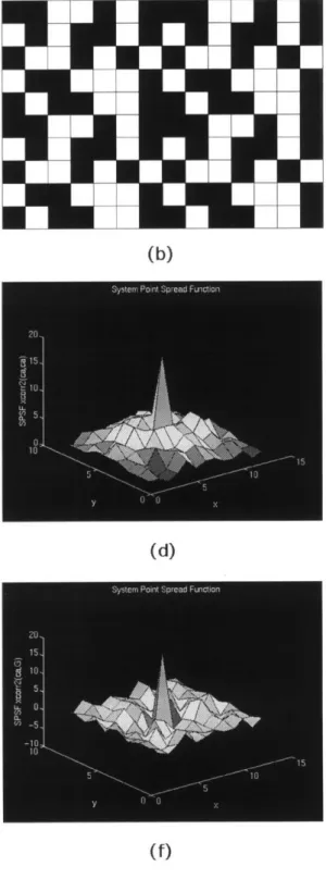
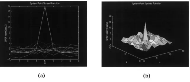
5-1 URA coded aperture design 1: a pseudo-noise pattern and its SPSF.. 53
5-2 URA coded aperture design 2: an optimal pattern and its SPSF. . ... 55
5-3 URA coded aperture design 2: an optimal pattern and its SPSF based on a balanced decoding algorithm ... .. 56
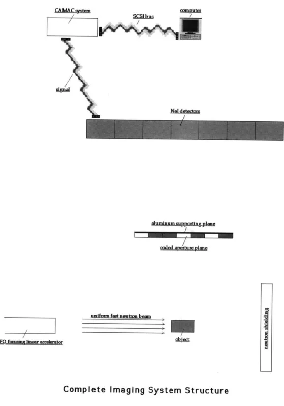
6-1 Our complete CAFNA imaging system structure. . ... . . 61
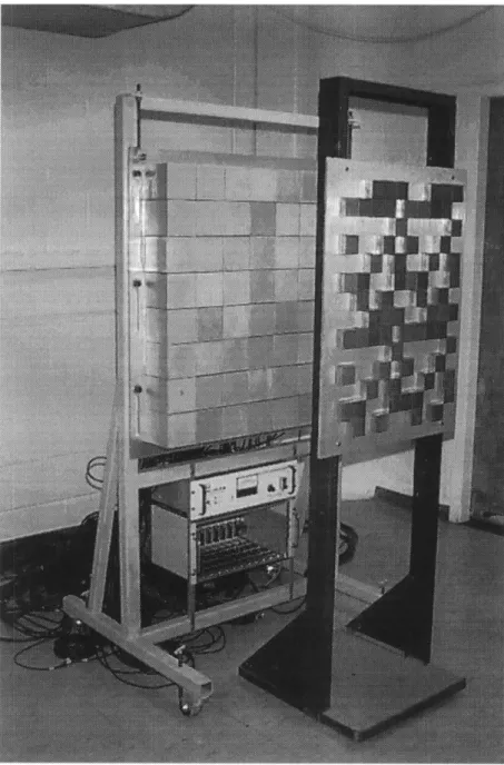
6-2 Our actual coded aperture imaging system. . ... . . 62
7-1 Reconstructed images for lead shielding: a point source ... 67
7-2 Reconstructed images for lead shielding: various source geometries. . 68 7-3 Reconstructed images for uranium shielding: a point source. ... 69
7-4 Reconstructed images for uranium shielding: various source geometries. 70 A-1 Mass absorption coefficients of the elements for X rays and neutrons. 76 A-2 Fast neutron elastic scattering cross-sections for various nuclear elements. 77 A-3 Fast neutron activation cross-sections for various nuclear elements. . . 78
A-4 Total fast neutron cross-sections for various nuclear elements... 79
B-1 Coded aperture imaging system simulation geometry. . ... 83
B-3 Our actual coded aperture plane. ... ... . . . 85 B-4 Our actual detector system. ... ... . 86
List of Tables
2.1 Characteristics of explosives and drugs. . ... 15
3.1 Expected signature gamma-ray peaks from neutron activation of various nuclear elements. . . ... . . . .... . 32
3.2 Suggested signature gamma-ray peaks from neutron activation of various nuclear elements in explosive detection. . ... 33
4.1 Comparison of past, present, and future coded aperture cameras. . .. 49
A.1 Gamma-ray penetration for lead and aluminum shielding. ... . 80
A.2 Gamma-ray penetration for uranium and aluminum shielding ... 81
C.1 Neutron activation analysis Monte Carlo simulation data. ... . 88
C.2 Detector response for a lead coded aperture plane... 89
Chapter 1
Introduction
Detection of hidden explosives is a long-term security project throughout the world. Various methods have been proposed and tried. Among them, nuclear techniques have unique advantages in identifying nuclear elements that are characteristic of nor-mal explosives. In this thesis, fast neutron activation analysis techniques and coded aperture imaging methods have been employed to realize a material detection system. An imaging system prototype has been built, and Monte Carlo simulations have been performed with good results. This technique can also be used for drug detection, as well as general nuclear elemental identification.
1.1
Background and Problems
Explosives and drugs are transported illegally by various methods such as hidden terrorist explosives in airplanes. Unlike other transportation methods, explosives in
an airplane seriously jeopardize the lives of the passengers, thus causing a security problem. This issue was addressed by the Federal Aviation Administration (FAA) of the US Department of Transportation. Research on the detection of hidden explo-sives has been performed nationwide for many years [19]. It is desirable to create a detection system for airports to screen passengers' luggage for explosives, as well as other contraband. Once this system is realized, it may be used in other places such as custom stations as well. During earlier research, it has been found that nuclear
meth-ods can be employed to detect not only explosives, but also other contraband such as drugs without additional cost; thus research on nuclear techniques for explosive detection has multiple potential benefits.
In the past ten years, various techniques have been tried worldwide, including physical, chemical, electrical, and nuclear techniques. Nuclear techniques, including photon, neutron, and nuclear resonance techniques, have potential advantages in identifying nuclear elements. Neutron techniques, including neutron time-of-flight
(TOF) and neutron activation analysis methods, have been shown effective. This thesis employs a combination of neutron activation analysis techniques and coded aperture imaging methods.
1.2
Contributions of This Thesis Project
The major contributions of this thesis project are summarized as follows:
* Monte Carlo simulations have been performed for neutron activation analysis methods in explosive detection. We have shown the feasibility of fast neutron activation analysis techniques and found the signature gamma-ray peaks most suitable for explosive detection;
* The coding pattern of our coded aperture imaging system has been optimally designed to achieve a good signal-to-noise ratio (SNR) and spatial resolution. Theoretical calculations and Monte Carlo simulations of the system have been performed;
* A coded aperture imaging system has been designed and partly built, including a big sodium iodide detector array composed of 64 detectors (a 10x10 cm2 cross-sectional area for each detector), a coded aperture plane (a URA pattern of two mosaics of an optimal 7 by 5 basic pattern in each dimension) composed of lead squares and an aluminum supporting plane, and associated electronics;
* The response (gain) of the detector array of the coded aperture imaging system has been measured and related software has been developed;
* System performance analysis and tests by Monte Carlo simulations have been implemented.
In summary, in this thesis project, we have tried a novel imaging method (coded aperture imaging of high energy signature gamma rays produced by fast neutron activation, or CAFNA, which means coded aperture fast neutron analysis) in explosive and drug detection, and have shown the advantages and feasibility of its practical applications. This technique is also applicable to other nuclear elemental identification cases. Nuclear techniques have unique advantages in the detection of contraband, including explosives and drugs, and their use with coded aperture methods brings an improved SNR and good spatial resolution, which have shortened the detecting and imaging time, and decreased the activation of the objects under examination as well. The project is successful and future development, especially an experimental test of the system, is worthwhile.
1.3
Thesis Outline
This thesis consists of eight chapters in addition to appendices and a bibliography. Chapter 1 (this chapter) is an introduction to the background and the thesis struc-ture. Chapter 2 discusses the problems and reviews current research status of ex-plosive and drug detection. Nuclear techniques are emphasized. Chapter 3 describes our Monte Carlo simulation methods and results for fast neutron activation analysis techniques in explosive detection. Signature gamma-ray energies that are most suit-able for explosive detection have been obtained. Chapter 4 describes the theory of coded aperture imaging methods, including coding and decoding methods. Chapter 5 discusses my optimal design of the coded aperture pattern and analyzes our system response (point-spread function) and performance. Chapter 6 describes the structure of our complete CAFNA imaging system. Chapter 7 shows the Monte Carlo simu-lation tests of our complete imaging system. Chapter 8 summarizes the results and conclusions we have obtained during this thesis project. Future development is also suggested there. The appendices contain relevant and important information that is
not included in the thesis body, such as the data, tables, figures, and source codes developed in this thesis project. The bibliography is included for further reference.
Chapter 2
Methods for Explosive Detection
2.1
Detection Requirements
A practical explosive and drug detection system at an airport requires a high detec-tion speed (6-8 seconds per piece of luggage) and an acceptable (10-20%) negative alarm rate.' Side effects, such as the activation of the objects under examination, are to be minimized. Nondestructive detection is required, and spatial resolution is expected to be several centimeters in each dimension. Information regarding whether contraband exists is the major goal, which is used for decision making. In short, the first requirement is a nondestructive contraband detection system for reliable decision making, and the second requirement is an imaging system for contraband localiza-tion. In other application cases, such as nuclear elemental identification, material detection, or object imaging, the requirements may be different.
A system employing coded aperture methods has improved sensitivity, thus re-sulting in a lower dose and less activation to the object under examination. Coded aperture methods will be discussed in detail later in this thesis.
1The probability of the existence of explosives in passengers' luggage at an airport is 0.1 ppm.
The negative alarm rate is defined as follows: If the number of the suitcases that are determined as
explosive containers by the detection system is n, and m suitcases of which do not contain explosives,
then the negative alarm rate is M, and the positive alarm rate is 1- m. A lower negative alarm rate is preferable.
Table 2.1: Characteristics of explosives and drugs.
Content Ratio Density
Explosives O, N rich; C, H poor low C/O ratio high O, N density Drugs C, H, Cl rich; 0, N poor high C/O ratio
-Benign Goods H, C, N rich; O poor - low N density
2.2
Characteristics of Explosives
Detection is based on the characteristics of the target materials - contraband such as explosives and drugs in our research project. Normal explosives have been shown to have a high nitrogen content, a low carbon-to-oxygen ratio, and high nitrogen and oxygen densities [15]. Drugs, such as cocaine and heroin, have been shown to have a high carbon-to-oxygen ratio, high carbon and chlorine contents, and little nitrogen [15]. Nuclear techniques based on these facts can be used and are described in detail in later parts of this chapter because nuclear techniques can identify nuclear elements directly. Detection can also be based on specific molecules rather than in general, which means different contraband molecules have to be identified based on their different properties. Because general hidden explosives and weapons usually contain metal components, a metal detector can be used, although plastic explosives and weapons cannot be found by this method. Characteristics of explosives and drugs in general, which are used in nuclear techniques, are summarized in Table 2.1.
2.3
Detection Methods
Various methods can be employed for explosive detection [23], including physical, chemical, electrical, nuclear, and special methods; and they are described below. It is necessary to note that although all these methods have their special properties, and some of them are more effective than others, they are usually complementary to each other.
2.3.1
Physical Methods
Physical methods are based on physical processes or the physical properties of the material under examination.
Ultrasound Imaging Ultrasound is used in medical imaging. It is very safe and
has high spatial resolution. It could be used for general imaging as well. However, it is unlikely to be effective in explosive detection because it depends on the physi-cal density difference in the object while explosives have no special physiphysi-cal density properties; but weapons may be detected if they contain a high density cover.
Luggage Check Luggage check is a basic method. It involves in labor work and is
slow and inconvenient. However, it is definitely necessary, especially for verification when contraband is found by other methods.
2.3.2
Chemical Methods
Chemical methods are based on chemical reactions or chemical properties of the material under examination. X-ray techniques are treated as chemical methods here because the photon sources are from orbital electrons and the interaction is in the atomic level.
Electron Spin Resonance Imaging Electron spin resonance (ESR), also called
electron paramagnetic resonance (EPR), is the selective absorption of weak radio-frequency electromagnetic radiation by unpaired electrons in the atomic structure of certain materials that simultaneously are subjected to a constant, strong magnetic field. It investigates the nature of chemical bonds within molecules by identifying unpaired electrons and their interaction with the immediate surroundings. It can identify molecules directly, but seems inefficient in contraband detection because too many kinds of contraband exist.
X-Ray Imaging X-ray imaging can be implemented in a two-dimensional or
three-dimensional way, which is called X-ray planar radiography or X-ray tomography re-spectively.
X-Ray Planar Radiography X-ray planar radiography techniques use X rays,
which are easily available low-cost radiation sources. They are photon transmission techniques and are based on the measurement of electron density in the object under examination. The photon transmission rate (or attenuation coefficient) is continuous versus the atomic numbers of the objects with which the photons interact; thus this method cannot easily identify elements well if the materials have close atomic num-bers. Photons can be shielded by high electron density materials, for example, high atomic number and high physical density materials, to prevent detection. Another drawback is that only two-dimensional information can be obtained. X-ray planar ra-diography is currently used in most airport luggage screening systems because hidden explosives may contain high physical density metal components and weapons usually
have a high density cover.
X-Ray Tomography X-ray tomography (also called X-ray CAT)2 uses multiple
projections of an X-ray beam and gets three-dimensional information about the elec-tron density distribution in the object under examination. This method cannot easily well identify elements if the materials have close atomic numbers. Photons can be shielded by high electron density materials to prevent detection. It is a relatively slow method because it needs to collect data from different directions; thus it usually in-volves in mechanical rotations, and computing-time-consuming back-projections and reconstruction in the postprocessing.
2.3.3
Electrical Methods
The common and widely used electrical method is metal detection.
Metal Detection Metal detectors are widely used at airports and custom stations today because they are simple, cheap, and effective; and common hidden explosives and weapons contain metal components. This method employs an electric field, which will be disturbed and thus causing an alarm if a conductor such as a metal component enters the field. However, modern weapons and explosives can be made without metal;3 thus they cannot be found by this method.
2.3.4
Nuclear Methods
Nuclear methods are based on nuclear structures and properties, and can be used to detect nuclear elements or molecules. They include gamma-ray, nuclear resonance, and neutron techniques. Nuclear methods have unique advantages because they can detect the general properties of explosives by identifying and localizing (imaging) nuclear elements directly. The problem is to control the dose deposited to the object under examination.
Gamma-Ray Techniques Gamma-ray techniques are very like X-ray techniques, except that a gamma-ray source is used, which usually has a high energy and thus high penetration capability and a large detection region. Photon attenuation is usually lowered with an increase in the photon energy; thus gamma-ray techniques generally have bigger signal than X-ray techniques.
Gamma-Ray Planar Radiography It is similar to X-ray planar radiography
except that high-energy gamma-rays are used to obtain larger signal.
Gamma-Ray Tomography It is similar to X-ray tomography except that
high-energy gamma-rays are used to obtain larger signal.
Nuclear Resonance Techniques Nuclear resonance techniques include nuclear magnetic resonance and nuclear quadrupole resonance techniques.
Nuclear Magnetic Resonance Imaging Nuclear magnetic resonance (NMR)
phenomenon is the selective absorption of very high-frequency radio waves by certain atomic nuclei that are subjected to an appropriately strong stationary magnetic field. It can be used to image special atomic nuclei whose nuclear magnetic moments are not zero. However, the strong external magnetic field is not preferable in practical applications since some stuffs in luggage, such as watches and credit cards, can be damaged.
Chemical Shift Imaging Chemical shift imaging is regarded as a nuclear
method rather than a chemical method because the signal is from nuclear mag-netic resonances of the target materials, although the chemical environment (chemical bonds or orbital electron coupling) changes the effective magnetic field to the nuclei and thus causing the NMR spectrum shift. It can image molecules. However, it seems impractical to use this method for contraband detection because too many kinds of contraband molecules exist. The strong external magnetic field is also not preferable.
Nuclear Quadrupole Resonance Imaging The interaction of a nuclear
elec-tric quadrupole moment with the elecelec-tric field generated by the surrounding electrons causes nuclear quadrupole resonance (NQR). NQR methods employ external electric fields and radio-frequency (RF) pulses to produce NQR signal for nuclei whose nu-clear electric quadrupole moments are not zero. These nuclei include nitrogen, which is of interest in explosive detection. This technique has no radiation hazards and shows potential applicability, although a shielded object cannot be detected by this method.
Neutron Techniques Neutron techniques use neutrons or neutron-induced gamma rays for detection and imaging. Fast neutrons are used because of their higher pene-tration capability and usually larger activation cross-sections which cause gamma-ray emission. A short detection time is needed for practical applications.
Fast Neutron Planar Radiography This method is the measurement of the
spectrum of the transmitted fast neutrons. It obtains a two-dimensional distribution of neutron interaction cross-sections of the object under examination, and may result in a high dose and possibly poor spatial resolution due to scattering of the neutrons. Unlike photon attenuation coefficients, fast neutron interaction cross-sections are not continuous versus the atomic numbers of the absorbing materials (see Figure A-1) [16]. Fast neutron spectroscopy depends on either detecting the energy spectrum of the transmitted neutrons, which requires a broad fast neutron source (a fast neutron
source with a uniform energy spectrum), or tuning the incident fast neutron energies, which requires a narrow fast neutron source (a monoenergetic fast neutron source).
Fast Neutron Tomography This method obtains a three-dimensional
distri-bution of neutron interaction cross-sections in the object under examination by fast neutron projections from various directions and reconstruction (back projection) tech-niques. The incident fast neutron beam and the measurement of the transmitted fast neutron spectra are from different directions. This technique needs several projections and is slow because mechanical rotations are usually involved in and reconstruction is computing-time-consuming. It has the same problems of neutron scattering and high dose hazards as in the previous method.
Fast Neutron Activation Analysis This method employs a fast neutron beam to bombard the object under examination, and gamma rays emanate because of neutron capture or neutron inelastic scattering with the elements (nuclei) of the object.4 Different gamma-ray energy spectra correspond to different nuclear elements in the object; thus these gamma rays are characteristic to the nuclear elements and are called signature gamma rays. By precisely measuring these gamma-ray spectra (energies and the intensity for each energy), it is possible to determine the type and
4
Neutron activation usually designates only neutron capture (n, -y) reaction, which induces
gamma rays. In this thesis, neutron inelastic scattering is also considered. Neutron activation analysis is the analysis technique that quantitatively determines the nuclear elemental densities in the object under neutron bombardment based on the precise measurement of the neutron-induced gamma rays.
quantity (density) for each corresponding nuclear element. The signature gamma-ray intensity (counts) is proportional to the multiplication of the neutron interaction cross-sections with the nuclear elemental density.5 We obtain information about the neutron reactions in the object by imaging these gamma rays using methods such as single photon emission computed tomography (SPECT) or coded aperture techniques, both of which obtain three-dimensional information about the nuclear elemental dis-tribution in the object. Neutron activation analysis techniques directly identify and localize different nuclear elements [2].
If a continuous fast neutron beam is used, coded aperture methods can be em-ployed to image the gamma-ray sources; and the methods are called coded aperture fast neutron analysis (CAFNA) techniques.6 If pulsed fast neutrons are used, neutron time-of-flight methods can be employed to image the gamma-ray sources [6]; and the methods are called pulsed fast neutron analysis (PFNA) techniques.7 Both types of methods can obtain nuclear elemental (position) distribution information; thus they are three-dimensional imaging techniques.
The main advantage of the neutron activation analysis technique over other nu-clear techniques is the capability of directly and quantitatively identifying and imaging nuclear elements with good performance; thus this technique is applicable to general explosive detection.
2.3.5
Other Methods
Other methods are sometimes very useful. Valuable information could be the most efficient way of finding contraband. Trained dogs can recognize several materials by smelling. Service people may find doubtful persons by experience and intuition. These methods are useful as complementary but not reliable.
5
We only consider signature gamma rays of high energies (E, > 1 MeV). They emanate from the object under examination with very small attenuation.
6CAFNA techniques are employed in this thesis. 7
People in the Advanced Nucleonics Division at the Science Applications International
2.3.6
Conclusions
Contraband detection can hardly be done well by solely one method [20]. Multiple, relatively less complicated systems, together usually work better than single very complex ones [27]. For general purpose contraband detection, nuclear techniques, such as gamma-ray or neutron techniques, have unique advantages:8
* high penetrability,
* high sensitivity,
* high selectivity,
* ability of quantitative nuclear elemental analysis,
* amenability to advanced data analysis and automated decision making.
Compared to other methods, nuclear techniques can do nondestructive elemental identification. Instead of detecting some specific kinds of molecules or contraband, nuclear techniques can detect the general characteristics of contraband by quantitative nuclear elemental identification and localization, thus have higher applicability. Other methods, such as metal detection, are complementary and necessary.
2.4
Fast Neutron Activation Analysis Methods
Neutron activation analysis is one of the most promising techniques in contraband detection. The nature of neutron interaction and the time scale depend on the incident neutron energy; and the processes are shown in Figure 2-1. We will concentrate on fast neutron-induced prompt gamma rays which occur on a short time scale. We need low activation and a short detection time for practical applications. Activation lower than 2 mRem/hour is required and a detection speed of 600-3000 pieces of luggage per hour is preferred at an airport. Both require that the detection system collects
'This benefits from a talk by Dr. Tsahi Gozani, senior VP and chief scientist, from SAIC in Santa Clara of CA, USA.
the signature gamma rays very efficiently; in other words, the system should have high sensitivity, especially when spatial resolution is to be obtained. We use fast neutrons instead of slow neutrons as an activation source because fast neutrons have large penetration capability which causes a large detectable region, and have large activation cross-sections which cause strong gamma-ray signal.
Fast neutrons have advantages over slow neutrons in their larger activation cross-section peaks (o) with various elements of interest,9 which result in gamma-ray emission. a. is non-zero for almost every element in the nuclear periodic table. For slow neutrons, the interaction is mainly elastic scattering for most nuclei of interest'0 and are of little use if our methods are based on signature gamma-ray detection. Moreover, the penetration capability of slow neutrons is much poorer than that of fast neutrons; this also prevents using slow neutrons as the source. In explosive detection, we are especially interested in carbon, nitrogen, and oxygen nuclei. Typical neutron capture reactions with them are
12
C +
13n-
1
3 +14N + n -- 15N + Y,
160 + -n __ 170o + .
Neutron cross-sections for elastic scattering (ae), activation (a,), and total inter-action (at) with various elements of interest are shown in Figures A-2, A-3, and A-4 respectively. Neutron interaction that induces gamma rays is treated the same as neutron activation in this thesis.
In PFNA techniques, it is very important to use fast neutrons with an energy cor-responding to neutron interaction cross-section peaks (a.) of the nuclear elements of interest to guarantee that neutron first-collisions (single-scattering) dominate.
9These elements of interest in explosive and drug detection are hydrogen, carbon, oxygen,
nitro-gen, and chlorine.
10
For some nuclei such as boron-10, lithium-6, and helium-3, ~y for thermal neutrons is larger than that for fast neutrons. However, they are of little interest in contraband detection.
Cr
--0-
:E
4'
u,
SLOWING DOWN TIME1 THERMALIZATION i TIR
Figure 2-1: Neutron interaction and the time scale.
The time scale for various neutron interaction and the induced gamma rays is shown in this figure. We see that neutron-induced gamma rays can be observed within a millisecond (ms). Detection based on these gamma rays is used in this thesis.
I-I. 0 Mi B. U' -0 I-LU 14 MeV z a C I--2 MeV
z
a U. C5(a
z
eV 0.025 PV I-C' CDL %_ýC fA TIME (Ms I ME ! IThe scattered neutrons have lower energies and smaller interaction cross-sections or smaller interaction probability; thus their interaction is not important. Neutron first-collision domination is essential in keeping good spatial resolution of a PFNA imaging system because spatial resolution is obtained through timing of the pulsed fast neutrons and interaction of the scattered neutrons will disturb the timing and degrade the spatial resolution if the (scattering) effect cannot be omitted. In CAFNA techniques, neutron first-collision domination is less important because we detect the total signature gamma-ray counts in a period of time (the detection or data collection time), and no timing information of the incident neutrons is needed.
Signature gamma rays are collected as raw data. They are expected to have large statistical deviations due to the low neutron activation and the small photon collection time during detection in order to avoid a high dose to the object under examination and to keep a high detection speed. Photon detection techniques which have high sensitivity are needed, thus better data statistics may be obtained with increased number of photons collected. Without degrading the system spatial resolution, two methods are possible to image the photons in fast neutron activation analysis tech-niques using a continuous neutron beam: conventional SPECT, and coded aperture techniques. Coded aperture methods, which will be discussed in detail later, can pro-vide a solution (the SNR improved by a factor of L without losing spatial resolution, compared to a single pinhole imaging system, where N is the number of open coded apertures) [1]. Multi-resolution techniques may further improve the performance of this method by improving the spatial resolution [4] of an image from poor data.
Fast neutrons are usually difficult to shield. Hydrogen-rich materials such as water and polyethylene can diffuse a fast neutron beam, but our Monte Carlo simulations show that these shielding materials cannot prevent neutron activation analysis tech-niques because different nuclear elements have different signature gamma-ray spectra which are composed of high energy photons. Although the count rates of the gamma rays of the energies of interest may decrease due to the reduced neutron flux caused by the neutron shielding, they decrease in proportion to all elements except the shielding elements and still represent the nuclear elemental densities of our interest.
High electron density materials can attenuate the signature gamma rays. How-ever, because these gamma rays have high energies, they are difficult to shield. For 1.25 MeV photons, 3.5 cm lead or 1.9 cm depleted uranium is needed to attenuate the photon intensity by 90%. For 6 MeV photons, thicker materials are needed. The small attenuation of the high energy photons in the object under examination causes more photons to emanate from the object; thus larger photon signal can be detected, which can be easily well distinguished from the background noise. In addition, be-cause the photon attenuation in the object is very small, the photon counts represent the elemental density in the object. On the other hand, high energy photons cause a shielding problem in the coding mask (coded aperture plane) in CAFNA techniques because more photons can penetrate the opaque area and decrease the SNR. However, the overall effect is positive because we really want more photons to come out from the object, which is the starting point that determines the SNR.
In the coded aperture methods (CAFNA), collecting signature gamma rays, then reconstructing the three-dimensional nuclear elemental (photon source) density dis-tribution is a little like the conventional SPECT methods. However, unlike SPECT, the coded aperture method is a planar imaging technique and needs only one projec-tion; thus the corresponding system is simple and the detection time is small because no mechanical rotations are involved in. The method used to collect photon signal is like planar radiography, but the reconstructed images have depth information; thus this technique has tomographic capability. Although two orthogonal projections may be performed, which are somewhat like simple tomography [35], the results did not show much more benefits. The nice results from Barrett's system [35] have given us confidence for continued research on this method.
Chapter 3
Monte Carlo Simulations of Fast
Neutron Activation Analysis
Techniques
3.1
Simulation Model Geometry
In fast neutron activation analysis methods, the difficult thing is to distinguish ex-plosives from benign materials with a high nitrogen content such as wool and nylon, which share some common characteristics with explosives. In my Monte Carlo sim-ulations, I used a cylindrical geometry model and let the fast neutron beam pass through explosives, such as TNT, and one or several types of benign materials. The simulation model geometry is shown in Figure 3-1.
3.2
Neutron Sources
3.2.1
Optimal Neutron Sources in Explosive Detection
In Section 2.4, we show that fast neutrons are better than slow neutrons in contra-band detection that uses neutron techniques such as neutron activation analysis. From the neutron activation cross-section curves given by Gozani [15], which are shown in
II --- 'C c, C) C C) C-4 1-4 H C I I Ca~ t.j ra* j '.' iq* '00
Figure 3-1: Fast neutron activation analysis Monte Carlo simulation model geometry. This is my Monte Carlo simulation model geometry used to test fast neutron ac-tivation analysis techniques in explosive detection. It is based on the output of a geometric plot of my MCNP programs.
R-B
Figure A-3 on page 78, we see that neutrons of energies higher than 8 MeV are optimal because these neutrons have large activation cross-sections (a.) with carbon, nitrogen, and oxygen, which are the elements of interest in explosive detection. Because when incident neutrons have an energy above 8 MeV, all these nuclear elements have large cross-sections of either neutron inelastic scattering or neutron capture reactions, both of which induce gamma rays, the selection of neutrons of 8 MeV or a higher energy would be optimal in neutron activation analysis techniques. For PFNA techniques, 8.15 MeV neutrons are optimal because neutron first-collision domination exists for this neutron energy, and neutrons scattered off the incident beam have smaller en-ergies and substantially smaller activation cross-sections; thus their existence is not important and can be largely omitted, and good spatial resolution is possible. For CAFNA techniques, which is employed in this thesis, neutrons of energies higher than 8 MeV would be fine. We do not emphasize neutron first-collision domination because no neutron timing information is needed. Neutron interaction cross-sections versus neutron energies with various nuclear elements of interest in explosive detection can be found in Figures A-2, A-3, and A-4.
Fast neutrons can be obtained from various sources, such as reactors, accelerators, spontaneous fission materials, and photon-neutron (y, n) reaction materials. In order to obtain high energy (E, > 8 MeV) neutrons, an accelerator source is a good solution because it can provide durable neutrons of higher energies by increasing the acceler-ation voltage of the ions, and it is also portable. Common neutron sources provide neutron energies of 14.1 MeV from a d(t,n)a reaction (Q = 17.6 MeV), 1 MeV to 10 MeV from an accelerator, 1 MeV from a nuclear reactor, and several MeVs from other sources such as spontaneous fission materials.
3.2.2
Our Neutron Source
Fast neutrons with energies between 1 MeV and 10 MeV are obtainable from small accelerators, although the current available accelerator-based neutron source in the MIT Laboratory of Neutron Tomography [31] is expected to yield neutrons with
a highest energy peak of 4.5 MeV.1 The actual neutron energy spectrum from the reaction2 9Be(d,n)loB depends on the beryllium target thickness for a fixed deuteron energy and must be measured experimentally. For 1 MeV incident deuterons and a thin metallic beryllium target foil, the released neutrons have strong 5.3 MeV and 4.5 MeV peaks, as well as smaller 3.7 MeV, 3.2 MeV, and 1.8 MeV peaks at a 00 scattering angle [32]. For 0.9 MeV incident deuterons and a thick beryllium target, the peaks in the neutron spectrum shift to 3.1 MeV and 1.6 MeV [17]. The magnitude of the neutron energy spectrum is small elsewhere. Our (accelerator) neutron source uses 0.9 MeV deuterons, but the target thickness may not be the same as that in the neutron spectrum measurements whose data are cited above; thus the 4.5 MeV neutron peak for our source is just an approximation of the neutron peak of the highest energy. The reaction is
9Be + d -- n + 10B + Q.
The Q value is 4.363 MeV if the daughter products are in their ground states, and the neutron carries away 3.966 MeV from the energy released (Q value) in this reaction. The deuterons are accelerated using a radio-frequency quadrupole (RFQ) focusing linear accelerator (linac) model DL-1 from the AccSys Technology, Inc. The RFQ linear accelerator "uses the electrical component of a variable RF EM field to accel-erate deuterium nuclei along a linear path to 0.9 MeV," and "uses the quadrupole magnetic component to focus the particle beam onto a 9Be target." [28] The static
acceleration voltage is 30 KV, while the RFQ focusing wave gives deuterons an addi-tional 870 KeV energy during their acceleration; thus the deuterons are accelerated to 900 KeV before they hit the target - a piece of beryllium (9Be). After they hit the 9Be nuclei, compound nuclei 11B are formed and are in their excited states. Each 11B
10ther neutron energy peaks of lower energies are expected to exist.
2This is the reaction used to produce fast neutrons by the accelerator in the MIT Laboratory of
nucleus quickly splits into a 10B and a neutron:
B -- 10B + n +
Q',
where Q' is the energy released in this reaction.
The neutron carries away most of the energy released in the process, and the product 10B may be in its ground state or an excited state. Neutrons are released in all directions; and the neutron spectra are different in different directions. Earlier experiments have shown that most neutrons have an energy of 4.5 MeV or 5.3 MeV at a 00 scattering angle for 1 MeV incident deuterons and a thin beryllium target [32].
For a thick beryllium target or a lower deuteron energy, the neutron energy peaks in the spectrum will shift to the lower energy side. The exact neutron spectrum is de-termined by the deuteron energy, the thickness of the beryllium target, the directions of the released neutrons, the compound 11B energy structure [36], and the average
life time of each energy state of the 10B nucleus. Some experimental measurements of the neutron spectra at different angles for various incident deuteron energies and target thickness can be found in [17, 32, 37]. The exact neutron spectrum for our accelerator-based neutron source will be measured experimentally by foil resonance techniques and neutron scintillation detectors. Higher neutron energies can be ob-tained if appropriate 11B compound nuclear energy levels are found or higher deuteron energies are used. If the incident deuterons are accelerated to 4 MeV, neutrons of 8 MeV may be obtained from the same reaction.
3.3
Simulation Results
3.3.1
Expected Signature Gamma-Ray Spectra
Gamma rays are produced mainly in neutron capture reactions and neutron inelastic scattering by nuclei. They are called signature gamma rays because they are char-acteristic to the nuclear elements in the neutron interaction. Different nuclei have different energy structures; thus the gamma-ray spectra correspond to specific nuclei
Table 3.1: Expected signature gamma-ray peaks from neutron activation of various nuclear elements.
Element Gamma-Ray Peaks (MeV) Hydrogen 2.225
Carbon 4.43
Nitrogen 1.64, 2.31, 4.46, 5.10, 7.02 Oxygen 3.68, 3.85, 6.13, 6.92, 7.12
and can be used to identify nuclear elements.
From compound nuclear energy structures, signature gamma-ray peaks for neutron interaction with hydrogen, carbon, nitrogen, and oxygen nuclei are expected as shown in Table 3.1. Our Monte Carlo simulations suggest the most useful and distinguishable signature gamma-ray peaks for these nuclei in explosive detection, which are shown in Table 3.2.
3.3.2
Suggested Signature Gamma-Ray Spectra of
Explo-sives
Monte Carlo simulations have been performed using the MCNP software (Version 4A) from the Los Alamos National Laboratory to find out the most useful and distinguish-able signature gamma-ray peaks for explosives. I used 4.5 MeV and 5 MeV neutrons as the activation sources, and a model geometry as shown in Figure 3-1 on page 28. The distribution of the neutron and gamma-ray fluxes and spectra was measured, and the relevant results are included in Appendix C.
The energies of the most prominent signature gamma rays for activation of the key elements in general explosives are 4.43 MeV for carbon, 2.31 MeV and 5.1 MeV for nitrogen, and 3.68 MeV and 6.13 MeV for oxygen. Gamma rays of 2.225 MeV are from n-1H capture reactions and have strong peaks due to a normally high content of hydrogen in general goods. Our suggested signature gamma-ray peaks used in explosive detection are shown in Table 3.2. Some expected gamma rays are not distinguishable or have very poor statistics in our simulations; thus they are not
Table 3.2: Suggested signature gamma-ray peaks from neutron activation of various nuclear elements in explosive detection.
Element Gamma-Ray Peaks (MeV) Hydrogen 2.225
Carbon 4.43 Nitrogen 2.31, 5.10 Oxygen 3.68, 6.13
recommended for use in identifying the corresponding nuclear elements.
For a fixed energy of the incident activation neutrons, the signature gamma-ray counts can be used to represent the amount of neutron interaction with the corre-sponding nuclei. For a different incident neutron energy, the counts of the signature gamma rays can still be used to represent the amount of neutron interaction, but the quantitative relations between different nuclear elements in explosives may vary be-cause neutron activation cross-sections (oa) depend on neutron energies. We need to use an adjusting factor if we want to keep the same quantitative relations in explosive detection for different incident neutron energies.
Selected important data are shown in Table C.1 on page 88. For explosives and benign materials, a comparison of the carbon-oxygen ratio (C/O) and the contents of nitrogen and oxygen are listed in this table. High nitrogen and oxygen contents and especially a low carbon-oxygen ratio in explosives can be seen.
3.3.3
Discussion
Fast neutron activation analysis techniques in contraband detection may even work for high nitrogen content materials, although large background noise usually exists. We will see in later chapters that coded aperture imaging methods can improve the SNR without degrading the system spatial resolution, while multi-resolution methods may improve the image quality from poor data [4].
3.4
Conclusions
Fast neutron activation analysis techniques can be used to detect explosives, even when high nitrogen content benign materials exist. Signature gamma-ray energies used to calculate the densities of carbon, nitrogen, and oxygen are as follows: 4.43 MeV for carbon (12C), 2.31 MeV and 5.10 MeV for nitrogen (1 4N), and 3.68 MeV and
6.13 MeV for oxygen (160). Neutrons of energies higher than 8 MeV are preferable as the activation source, although 4.5 MeV neutrons may be used for detection. For different incident neutron energies, an adjusting factor can be used to keep the same quantitative relations in explosive detection.
Chapter 4
Theory of Coded Aperture
Methods
4.1
Introduction
Coded aperture methods were first proposed in 1961 by Mertz and Yang, who used a Fresnel zone plate (FZP) coding pattern [22]. A recent physical implementation was done by Barrett, et al. in 1992, who chose a uniformly redundant array coding pattern to realize a SPECT system [26, 30, 35]. Some other implementations can be found in Table 4.1 on page 49. A coded aperture imaging system is like a combination of a single pinhole camera and a multihole collimator system, but has higher sensitivity with tomographic capability.
4.2
Concept of Coded Aperture Methods
The concept of coded aperture methods is based on that of a single pinhole camera system. Single pinhole cameras and multihole collimator systems are described briefly in this part, then the concept of coded aperture methods is introduced.
4.2.1
Pinhole Cameras
A pinhole camera system consists of a single pinhole and a detector system that is position-sensitive. The detector system can be an Anger camera, or a scintillation detector array. The pinhole aperture performs the imaging operation while the de-tector system detects the image. Although the dede-tector system can be very efficient for photons, the pinhole system severely limits the number of photons that can arrive at the detectors. The pinhole size is proportional to the sensitivity, and inversely proportional to the spatial resolution of the system. Generally, the system sensitivity is low. A pinhole system has very limited tomographic capability.
4.2.2
Multihole Collimator Systems
A multihole collimator system consists of multiple parallel tube-like collimators and a detector system that is position-sensitive. Compared to a single pinhole system, the multihole collimator system loses tomographic capability. A good radiography can be done; and the spatial resolution is usually higher than that of a single pinhole system. As with pinhole collimators, this collimator typically passes only 0.01% of the radiation emitted by the object, thus causing a substantial signal loss and possibly poor statistics of the detected signal.
4.2.3
Coded Aperture Systems
There is inevitable trade-off between spatial resolution and sensitivity, as well as other features such as tomographic capability for a planar imaging system. In a single pinhole camera or a multihole collimator system, if the detection time is fixed and the detector system is the same, the only way to increase the sensitivity is to enlarge the aperture size or to increase the solid-angle of each detector unit, both of which will degrade the system spatial resolution. "If the way in which the resolution is degraded is chosen carefully, it is possible to postprocess the signal to recover the resolution and still enjoy improved statistical quality in the processed signal." [33]
arranged apertures to enlarge the total (photon) transmission area without losing spatial resolution.
Coded aperture techniques are different from conventional planar imaging methods in that the detected signal is not a directly recognizable image. The signal is encoded like a hologram and must be decoded before a visible image can be obtained. This is like tomography, which needs postprocessing to present the image.
Coded aperture methods include two processes: coding and decoding. First, in-formation about the object being imaged is coded in the detected signal; second, the detected signal is decoded to form the three-dimensional (3-D) image of the object. The coding process allows the reconstruction of an object slice at a particular depth in the object while blurring other slices in the object, thus resulting in tomographic capability. The decoding process is necessary and is not an image enhancement tech-nique, although image enhancement techniques can also be used.
Coding methods include one-dimensional (1-D) and two-dimensional (2-D) coding. A 1-D coding pattern is a line of specially arranged apertures, while a 2-D pattern is a 2-D aperture array. The former is a special case of the latter. Various coding patterns have been studied, including the patterns of a random array, a Fresnel zone plate, and a uniformly redundant array (URA). Theoretically, the apertures can be in any shape for the same system performance, such as polygons, circles, rings, or a mixture of them. Actually, the aperture shape is the same as the cross-sectional shape of the detector unit to improve the detection efficiency. The URA patterns have been shown to have the smallest artifacts in the reconstructed images [10] and a detector usage ratio of 100%. In order to obtain a satisfactory image, we need high sensitivity and high spatial resolution. The flat side-lobes of a URA system response function make URA coding a good candidate for practical applications. The advantages of URA coded aperture methods are an improved SNR, the same resolution as that of a single pinhole imaging system whose pinhole size is the same as the aperture size in the URA pattern [1], minimal side-lobes of the system response function, and tomographic capability [33].
the source point makes a shadow-casting of the coding pattern on the detector plane. If an extensive source is used, which can be treated as multiple point sources, the multiplexing of several such patterns will be recorded on the detector plane. The total number of photons (signal) recorded will be larger than that in a single pinhole system or a multihole collimator system because the total photon transmission area is increased, every photon source contributes to many detector units, and no collimators are used, thus resulting in an improved SNR. The image can be reconstructed after de-multiplexing (decoding) of the recorded signal.
In Figure 4-1, a position-sensitive detector system is used to record the transmitted photon signal. If detection time is not an issue, which means a long detection time is acceptable, and the photon source is stable (not time-variable), a single detector can be used to record the spatial distribution of the transmitted signal by moving through the whole shadow-casting area within a plane, although a line detector or a detector array can also be used to do the same thing. This is usually used only for a 1-D coding pattern, and can be called a time-sensitive detector system. It is equivalent to a position-sensitive detector system, and we focus on only the latter in this thesis because we need a short detection time in our practical applications.
4.2.4
Conclusions
A coded aperture imaging system has higher sensitivity than a single pinhole camera, but keeps the same spatial resolution. Both of these planar imaging methods have tomographic capability. A coded aperture imaging system has substantially higher sensitivity than a multihole system, and the latter cannot obtain 3-D information. A coded aperture system is faster and simpler than a tomography system because the former does not need mechanical rotations which are usually necessary in the latter, and the reconstruction in a coded aperture system is usually simpler than that in a tomography system. However, like other planar imaging techniques with tomographic capability, coded aperture methods may produce artifacts in the reconstructed images when 3-D information is obtained. Good coding patterns and decoding methods are needed to make the artifacts minimal.
Figure 4-1: Diagram of a coded aperture system for photon imaging.
This figure illustrates a coded aperture system for photon imaging [1]. The source point is not at infinity. We see an enlarged coding pattern projected from the source to the detector plane.
4.3
Fresnel Zone Plate Coded Aperture Methods
Fresnel zone plate (FZP) was the first coding pattern used in coded aperture imaging techniques. Detailed mathematical calculations about FZP coded aperture methods have been done by Mertz and Young [22]. Coded aperture imaging techniques are based on a pinhole camera imaging system. For a pinhole camera system, a small pinhole is needed in order to obtain good spatial resolution, in which case, the SNR may be small if the data collection time is short, because the area of the pinhole where signal passes through is small. To improve the SNR and still keep the same spatial resolution as that of a pinhole imaging system, coded aperture methods can be used. Instead of a single pinhole, multiple apertures are arranged in a special pattern, such as an FZP pattern, to record the signal from the source. The signal becomes bigger with an increase in the total aperture area. The immediately recorded signal is a shadow-casting of the coded aperture pattern (such as an FZP pattern) from the source and does not directly reflect the source shape. It needs to be decoded before a visible image of the source can be obtained [1].
4.4
Uniformly Redundant Array Coded Aperture
Methods
4.4.1
URA Coded Aperture Concept
A uniformly redundant array coded aperture pattern is composed of several mosaics of a basic pattern that is pseudo-random. If the repetition time of the basic pattern in each dimension is n, it is usually required that n is at least 2. If n is bigger, the system field-of-view (FOV) is bigger. However, the system resolution and sensitivity are the same for n > 2 if the detectors are the same. We need for n to be at least 2 to avoid the consideration of the edge effects of the coded aperture plane, and achieve a 100% detector usage ratio [11]. It is always the case that the shadow-casting of the URA coded aperture pattern covers the area of the whole detector array. That is to