READ THESE TERMS AND CONDITIONS CAREFULLY BEFORE USING THIS WEBSITE. https://nrc-publications.canada.ca/eng/copyright
Vous avez des questions? Nous pouvons vous aider. Pour communiquer directement avec un auteur, consultez la première page de la revue dans laquelle son article a été publié afin de trouver ses coordonnées. Si vous n’arrivez pas à les repérer, communiquez avec nous à PublicationsArchive-ArchivesPublications@nrc-cnrc.gc.ca.
Questions? Contact the NRC Publications Archive team at
PublicationsArchive-ArchivesPublications@nrc-cnrc.gc.ca. If you wish to email the authors directly, please see the first page of the publication for their contact information.
NRC Publications Archive
Archives des publications du CNRC
This publication could be one of several versions: author’s original, accepted manuscript or the publisher’s version. / La version de cette publication peut être l’une des suivantes : la version prépublication de l’auteur, la version acceptée du manuscrit ou la version de l’éditeur.
Access and use of this website and the material on it are subject to the Terms and Conditions set forth at
Vibration Characteristics of a Floor Sample
Rainer, J. H.; Pernica, G.
https://publications-cnrc.canada.ca/fra/droits
L’accès à ce site Web et l’utilisation de son contenu sont assujettis aux conditions présentées dans le site LISEZ CES CONDITIONS ATTENTIVEMENT AVANT D’UTILISER CE SITE WEB.
NRC Publications Record / Notice d'Archives des publications de CNRC:
https://nrc-publications.canada.ca/eng/view/object/?id=cc6c53b4-d39e-4dd3-9d82-be448c8ae548 https://publications-cnrc.canada.ca/fra/voir/objet/?id=cc6c53b4-d39e-4dd3-9d82-be448c8ae548rr
and G
VIBRATION CHARACTERIST
lGS
OF
A FLOOR SAMPLE
by
J.H.
Raine
i.Pemka
A54 ALY
DBR -Paper
No. 1271
Mvidon
o
f
BuUdlng ~eeeardi
NATIONAL RESEARCH COUNCIL OF CANADA
DIVISION OF BUILDING RESEARCH
ANALYZED
VIBRATION CHARACTERISTICS OF A FLOOR SAMPLE
byJ.H. Rainer and G. Pernica
Ottawa
March
1985VIBRATION CHARACTERISTICS OF A FLOOR SAMPLE
J . H . Rainer and G. P e r n i c a
ABSTRACT
V i b r a t i o n t e s t s c o n s i s t i n g of h e e l impacts by a person, s h a k e r impacts, and random s h a k e r e x c i t a t i o n s were c a r r i e d o u t on an 8.5 x 8.8
m
s t e e lj o i s t - c o n c r e t e s l a b f l o o r sample. S t r u c t u r a l v a r i a t i o n s t o t h e f l o o r sample i n c l u d e d r e s t r a i n e d and f r e e edge c o n d i t i o n s , two c o n c r e t e s l a b t h i c k n e s s e s , s e v e r a l j o i s t s t i f f n e s s e s , and t r a n s v e r s e b r a c i n g of t h e s t e e l j o i s t s . The lowest f o u r t o s i x n a t u r a l f r e q u e n c i e s , a s s o c i a t e d mode s h a p e s and modal damping v a l u e s were determined f o r v a r i o u s s t r u c t u r a l c o n f i g u r a t i o n s . Modal damping of t h e f l o o r sample was s i g n i f i c a n t l y i n c r e a s e d by t h e p r e s e n c e of one o r more persons on t h e f l o o r , whereas s t r u c t u r a l m o d i f i c a t i o n s had
r e l a t i v e l y l i t t l e e f f e c t . P r e d i c t e d and measured i n i t i a l peak a c c e l e r a t i o n s due t o h e e l impact and fundamental f l o o r f r e q u e n c i e s were a l s o compared.
INTRODUCTION
A s f l o o r systems i n b u i l d i n g s become s t r u c t u r a l l y more e f f i c i e n t , t h e y a l s o t e n d t o become more r e s p o n s i v e t o common dynamic l o a d i n g s s u c h a s people walking, dancing o r jumping, v e h i c u l a r t r a f f i c , and machinery. The main f a c t o r s c o n t r i b u t i n g t o t h i s i n c r e a s e d v i b r a t i o n s e n s i t i v i t y a r e
r e d u c t i o n s i n mass, s t i f f n e s s , and damping. Since t h e s e parameters dominate t h e dynamic behaviour of s t r u c t u r a l s y s t e m , a b e t t e r u n d e r s t a n d i n g and q u a n t i t a t i v e e v a l u a t i o n of them w i l l a l l o w t h e p r e v e n t i o n o r a l l e v i a t i o n of o b j e c t i o n a b l e v i b r a t i o n s .
An o p p o r t u n i t y t o s t u d y t h e s e parameters a r o s e when a f u l l - s c a l e f l o o r model became a v a i l a b l e f o r dynamic t e s t i n g . The o b j e c t i v e of t h e t e s t s was t o measure t h e dynamic p r o p e r t i e s of t h e composite s t e e l j o i s t - c o n c r e t e s l a b f l o o r sample and t o a s c e r t a i n how t h e s e p r o p e r t i e s were a f f e c t e d by
s t r u c t u r a l m o d i f i c a t i o n s t o t h e f l o o r sample. P a r t i c u l a r emphasis was p l a c e d on t h e e v a l u a t i o n of damping, a s t h i s parameter cannot a s y e t b e c a l c u l a t e d .
Some a s p e c t s of t h i s i n v e s t i g a t i o n have been d e s c r i b e d i n an e a r l i e r paper.l T h i s r e p o r t i s more e x t e n s i v e i n i t s p r e s e n t a t i o n of modal
f r e q u e n c i e s , mode s h a p e s , and modal damping r a t i o s .
EXPERIMENTAL PROCEDURE
The 8.8 x 8.5 m f l o o r sample comprised a nominally 75 mm t h i c k c o n c r e t e deck,* composite w i t h s i x 457
mm
deep s t e e l j o i s t s . The j o i s t s were*Since t h e measured t h i c k n e s s from c o n c r e t e c o r e samples was 81 mm, t h e s l a b
s u p p o r t e d on s t e e l g i r d e r s , which i n t u r n framed i n t o f o u r c o r n e r s t e e l columns. The edges of t h e sample were a l s o bounded by s t e e l beams ( s e e F i g u r e 1 f o r d e t a i l s ) .
I n s t r u m e n t a t i o n f o r measuring t h e dynamic r e s p o n s e of t h e f l o o r c o n s i s t e d of a c c e l e r o m e t e r s l o c a t e d a t t h e g r i d p o i n t s shown i n F i g u r e 2. The s i g n a l s from t h e a c c e l e r o m e t e r s were f i l t e r e d and a m p l i f i e d b e f o r e b e i n g r e c o r d e d on FM t a p e r e c o r d e r s . A p o r t a b l e o s c i l l o s c o p e and s p e c t r u m
a n a l y z e r were u s e d t o m o n i t o r t h e s i g n a l s d u r i n g t h e e x p e r i m e n t s . A t f i v e p o i n t s on t h e f l o o r ( l a b e l l e d A t o E i n F i g u r e 2 ) , dynamic l o a d s were
a p p l i e d from random s h a k e r e x c i t a t i o n , s h a k e r i m p a c t , and h e e l i m p a c t s by a person.
M o d i f i c a t i o n s t o t h e o r i g i n a l f l o o r sample c o n s i s t e d o f : 1 ) end beams s u p p o r t e d by screw j a c k s of a t y p e commonly used t o s u p p o r t f l o o r s i n t h e basements of h o u s e s , w i t h s u p p o r t e d o r u n s u p p o r t e d edge beams ( p o s i t i o n s shown i n F i g u r e 1 ) ; 2 ) suspended c e i l i n g and gypsum board c e i l i n g on t h e u n d e r s i d e of t h e f l o o r ; 3) d i a g o n a l s t e e l b r a c i n g between t h e j o i s t s ;
4 ) a 152 x 229 mm c o n c r e t e s t i f f e n i n g beam normal t o t h e j o i s t s ;
5 ) s t e e l - n e o p r e n e - s t e e l sandwich s t r i p s ( 6 x 76 mm
-
7 x 75 mm-
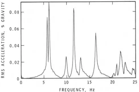
6 x 76 mm) b o l t e d t o t h e lower chord of t h e j o i s t s ; and 6 ) a 25 m c o n c r e t e t o p p i n g added t o t h e s l a b .F l o o r r e s p o n s e s produced by random and impact e x c i t a t i o n s were a n a l y z e d on a Hewlett-Packard 54238 s p e c t r u m a n a l y z e r t o o b t a i n n a t u r a l f r e q u e n c i e s and phase between t r a n s d u c e r l o c a t i o n s . Mode s h a p e s were drawn from
s p e c t r a l a m p l i t u d e s and phase. Modal damping r a t i o s were found by two methods: 1 ) a c u r v e - f i t t i n g p r o c e d u r e of t h e s p e c t r u m a n a l y z e r a p p l i e d t o t h e s p e c t r a l peaks of t h e F o u r i e r s p e c t r u m of t h e f l o o r r e s p o n s e ; and 2 ) f o r s h a k e r and h e e l impact s i g n a l s , t h e f r e e v i b r a t i o n decay c u r v e s were
hand-pass f i l t e r e d around t h e n a t u r a l f r e q u e n c y and l o g a r i t h m i c decrements computed. Examples of F o u r i e r s p e c t r a f o r s h a k e r random and impact
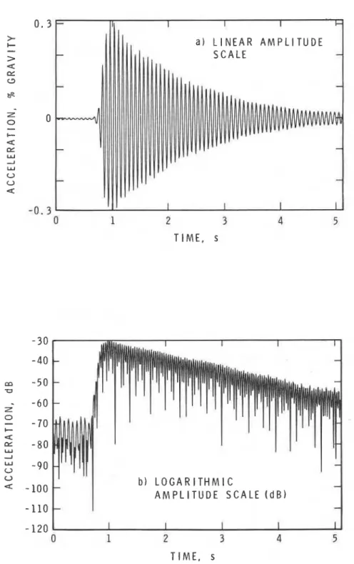
e x c i t a t i o n a r e shown i n F i g u r e s 3 and
4;
time r e c o r d s of f r e e v i b r a t i o n decay c u r v e s on l i n e a r s c a l e s a r e shown i n F i g u r e s 5 and 6 , and on l i n e a r and l o g a r i t h m i c s c a l e s i n F i g u r e 7 a and b. The v i b r a t i o n decay c u r v e s were o b t a i n e d by a d d i n g t h e s i g n a l s from s y m m e t r i c a l l y - p l a c e d t r a n s d u c e r s f o r mode 1 , a s y m m e t r i c a l mode, and s u b t r a c t i n g them f o r mode 2 , a na n t i - s y m m e t r i c mode. T h i s e l i m i n a t e d a n t i - s y m m e t r i c modes a l m o s t c o i n c i d e n t i n f r e q u e n c y from t h e f o r m e r , and symmetric modes from t h e l a t t e r . O t h e r u n d e s i r a b l e modal components were removed by s u i t a b l e band-pass f i l t e r i n g .
RESULTS
N a t u r a l F r e q u e n c i e s and Mode Shapes
T a b l e s 1 and 2 g i v e n a t u r a l f r e q u e n c i e s and a s s o c i a t e d mode s h a p e s a l o n g t h e j o i s t s and a c r o s s t h e j o i s t s , a s d e p i c t e d i n t h e t a b l e h e a d e r . N a t u r a l f r e q u e n c i e s w i t h a s t e r i s k s i d e n t i f y t h o s e modes whose s h a p e s c o u l d n o t be p o s i t i v e l y i d e n t i f i e d from t h e d a t a . They have been f i t t e d i n t o t h e t a b l e s by c o n s i d e r i n g t h e i r p o s i t i o n i n t h e s e q u e n c e of modal f r e q u e n c i e s .
For some of t h e h i g h e r modes i n T a b l e 1, r e l a t i v e l y l a r g e modal
a m p l i t u d e s were measured on t h e end o r edge beams, c o n t r a r y t o what might be e x p e c t e d f o r s u p p o r t e d end and edge c o n d i t i o n s . Although some s m a l l
amplitudes w i l l always be p r e s e n t due t o e l a s t i c s h o r t e n i n g of t h e j a c k s , t h e r e l a t i v e l y l a r g e amplitudes a r e thought t o be due t o l o c a l s e p a r a t i o n of t h e s l a b from t h e t o p f l a n g e of t h e end and edge beams. It i s t h e r e f o r e q u e s t i o n a b l e whether f u l l y - s u p p o r t e d end and edge c o n d i t i o n s apply t o t h e h i g h e r modes.
Table 2 p r e s e n t s n a t u r a l f r e q u e n c i e s and mode s h a p e s f o r t h e f l o o r sample w i t h s u p p o r t e d o r unsupported end and edge beams. A s a r e s u l t of reduced p e r i m e t e r r e s t r a i n t , t h e r e were more modes w i t h n a t u r a l f r e q u e n c i e s below 22 Hz f o r t h e unsupported t h a n f o r t h e f u l l y - s u p p o r t e d c o n d i t i o n s . It was d i f f i c u l t t o o b t a i n t h e mode shape f o r mode 3 because t h e e x c i t a t i o n
p o i n t was n e a r a node, e x c e p t f o r Run No. 111, w i t h e x c i t a t i o n a t l o c a t i o n E.
Measured mode shapes of t h e o r i g i n a l f l o o r sample a r e p r e s e n t e d i n F i g u r e s 8 t o 10 f o r v a r i o u s end and edge s u p p o r t c o n d i t i o n s . The p l o t t e d p o i n t s a r e t r a n s d u c e r l o c a t i o n s f o r which modal a m p l i t u d e s were determined. E x t r a p o l a t e d p o r t i o n s of t h e mode shapes a r e shown by dashed l i n e s . For s u p p o r t e d end and edge c o n d i t i o n s , modes w i t h s u c c e s s i v e l y h i g h e r n a t u r a l f r e q u e n c i e s c o n t a i n e d an i n c r e a s i n g number of n e a r l y s i n u s o i d a l l o b e s , o c c u r r i n g f i r s t a c r o s s t h e j o i s t s , and t h e n a l o n g t h e j o i s t s , a s shown i n F i g u r e 9.
The r e s u l t s of Tables 1 and 2 and F i g u r e s 8 t o 10 showed t h e f o l l o w i n g t r e n d s :
1)
Supporting t h e end beams p r i m a r i l y i n c r e a s e d t h e n a t u r a l f r e q u e n c i e s of modes w i t h nodal l i n e s p e r p e n d i c u l a r t o t h e j o i s t s . The l a r g e s t i n c r e a s e i n frequency o c c u r r e d i n t h e fundamental and t h e f i f t h mode.2 ) Supporting t h e edge beams had l i t t l e e f f e c t on t h e frequency of t h e fundamental mode, b u t s u b s t a n t i a l l y i n c r e a s e d t h e f r e q u e n c i e s of t h e second mode and h i g h e r modes w i t h nodal l i n e s p a t a l l e l t o t h e
j o i s t s . 3 ) A s i n 2 ) , t h e a d d i t i o n of s t i f f e n i n g elements p e r p e n d i c u l a r t o t h e j o i s t s p r i m a r i l y r a i s e d t h e f r e q u e n c i e s of t h o s e modes w i t h n o d a l l i n e s p a r a l l e l t o t h e j o i s t s . 4 ) The a d d i t i o n of 25 mm of c o n c r e t e t o t h e s l a b reduced t h e n a t u r a l frequency of a l l modes by a t l e a s t 5%.
The above o b s e r v a t i o n s g e n e r a l l y a g r e e w i t h what might be e x p e c t e d from p r i n c i p l e s of v i b r a t i o n t h e o r y p e r t a i n i n g t o p l a t e s .
A s m a l l d e c r e a s e i n t h e f i r s t and second modal f r e q u e n c i e s i s
d i s c e r n i b l e i n Table 2, between what were o r i g i n a l l y thought t o be i d e n t i c a l r u n s , Run 5 and Runs 8, 9 and 10. These d i f f e r e n c e s c a n be a t t r i b u t e d t o s l i g h t changes i n t h e p e r i m e t e r c o n d i t i o n s of t h e f l o o r sample. It i s thought t h a t j a c k i n g o p e r a t i o n s on t h e end and edge beams and t h e j o i s t s caused l o c a l c o n c r e t e c r a c k i n g and l o s s of bond between t h e s t e e l beams and t h e c o n c r e t e s l a b . F u r t h e r s e p a r a t i o n between t h e c o n c r e t e s l a b and t h e s t e e l beams may a l s o have o c c u r r e d a s t h e c o n c r e t e d r i e d and shrank. The r e s u l t i n g l o s s of bond would s l i g h t l y d e c r e a s e t h e end and edge s t i f f n e s s of t h e f l o o r sample and r e s u l t i n lower modal f r e q u e n c i e s .
Damping of t h e F l o o r Sample
Modal damping r a t i o s f o r s h a k e r impact and h e e l impact response were o b t a i n e d from t h e f r e e v i b r a t i o n decay u s i n g t h e r e l a t i o n s h i p :
where :
5
= modal damping r a t i o , f r a c t i o n of c r i t i c a l ;Xm = amplitude of t h e mth peak;
Xmh = a m p l i t u d e of t h e peak n c y c l e s l a t e r ;
6 = l o g a r i t h m i c decrement.
V i b r a t i o n decays f o r t h e f i r s t two modes a r e shown i n F i g u r e s 5 , 6 and
7.
A convenient d i s p l a y of t h e decay i n l o g a r i t h m i c a m p l i t u d e , shown i nF i g u r e 7b, provided a simple method f o r c a l c u l a t i n g t h e l o g a r i t h m i c decrement ( 6 ) by f i t t i n g a s t r a i g h t l i n e through t h e peaks. It a l s o
a f f o r d e d t h e o p p o r t u n i t y t o observe any changes i n t h e l o g a r i t h m i c decrement w i t h p r o g r e s s i v e l y s m a l l e r amplitudes; i . e . , t o d e t e c t amplitude-dependent damping. The l o g a r i t h m i c decrement f o r each mode and t h e modal damping r a t i o were computed f o r t h e f i r s t 20 c y c l e s e x c e p t where o t h e r w i s e noted.
Modal damping r a t i o s f o r s h a k e r impact and s h a k e r random e x c i t a t i o n were a l s o o b t a i n e d u s i n g t h e c u r v e - f i t t i n g a l g o r i t h m f o r F o u r i e r spectrum peaks provided by t h e Hewlett-Packard 53238 S t r u c t u r a l Dynamics Analyzer. Some r e s u l t s u s i n g b o t h p r o c e d u r e s a r e p r e s e n t e d i n T a b l e 3 f o r d i f f e r e n t c o n f i g u r a t i o n s of t h e f l o o r sample. I n g e n e r a l , comparable modal damping r a t i o s were o b t a i n e d u s i n g b o t h methods. On o c c a s i o n , however, t h e
agreement was less t h a n s a t i s f a c t o r y (Run 183, Mode 2 ) . T h i s may be due t o i n a d e q u a t e s p e c t r a l r e s o l u t i o n i n t h e F o u r i e r spectrum o r i n a p p r o p r i a t e placement of t h e c u r s o r s f o r bounding t h e s p e c t r a l peak of t h e c u r v e - f i t t i n g a l g o r i t h m on t h e spectrum a n a l y z e r .
Damping c o n t r i b u t e d by people: The h e e l impact has l o n g been a f a v o u r i t e s o u r c e of f l o o r e x c i t a t i o n because of i t s s i m p l i c i t y and i t s
resemblance t o o t h e r dynamic l o a d i n g s on f l o o r s such a s walking and j ~ m p i n g . ~ , ~ However, t h i s t e s t r e q u i r e s t h e p r e s e n c e of a t l e a s t one person on t h e f l o o r . A comparison of modal damping r a t i o s d e r i v e d from t e s t s demonstrated t h a t a s i g n i f i c a n t i n c r e a s e i n modal damping c a n r e s u l t when people a r e p l a c e d on a f l o o r t h a t h a s i n h e r e n t l y l i t t l e damping.
T a b l e
4
i l l u s t r a t e s t h i s e f f e c t by comparing modal damping r a t i o s d e r i v e d from h e e l impact w i t h t h o s e from s h a k e r impact t e s t s w i t h and without people on t h e f l o o r . The e f f e c t of one, two o r t h r e e p e r s o n s on t h e measureddamping r a t i o s i s demonstrated t h e r e .
The l o c a t i o n of a person on t h e f l o o r a l s o a f f e c t e d t h e amount of i n c r e a s e i n t h e t o t a l measured damping r a t i o . The r e s u l t s f o r t h e h e e l impact t e s t , Run No. 155, i n T a b l e s
4
and 5 show t h a t t h e modal damping r a t i o f o r t h e fundamental mode d e c r e a s e d a s t h e p e r s o n moved from l o c a t i o n A, t h e c e n t r e of t h e f l o o r , t o l o c a t i o n D. T h i s d e c r e a s e i n damping isa t t r i b u t e d t o d e c r e a s e s i n modal amplitude w i t h l o c a t i o n . I n T a b l e 5 t h e modal damping r a t i o s measured a t l o c a t i o n s B , C and D were a d j u s t e d by t h e s q u a r e of t h e r a t i o of modal a m p l i t u d e s r e l a t i v e t o l o c a t i o n A , r e s u l t i n g i n damping r a t i o s f o r p e r s o n s a s i f they were s t a n d i n g a t l o c a t i o n A. The
mathematical basis for this adjustment is presented in Figure
11and is
discussed in a later section. For the floor sample with supported end and
edge beams, each person standing at position A (the centre of the floor
sample), contributes between
0 . 8 0and
1 . 0 0 %of critical to the damping ratio
for the fundamental mode of the floor sample. Aspects of the mathematical
modelling of damping due to people are also treated in a later section.
The amount of modal damping also varied with the individual. Although
no systematic study was done in this series of tests, there are indications
that the damping contributed by people varied from person to person,
depending on weight and physique.
Changes in damping due to floor modifications: Major floor
modifications can be expected to result in different modal damping ratios as
new sources of damping ire introduced and others diminish. The following
modifications to the floor sample were investigated: end beams and edge
beams fully supported; suspended ceiling on underside of floor; gypsum board
ceiling on underside of floor; steel-neoprene damping strips bolted to
bottom chord of the joists. The results are summarized in Table
6 .For assessing the influence of various floor modifications, modal
damping ratios were determined from shaker impact tests. Heel impact tests
could not be utilized since they contained the additional damping of the
person doing the test. Modal damping was calculated from the logarithmic
decrement of the free vibration decay curve, as it was considered to give a
more reliable estimate than applying the curve-fitting algorithm of the
spectrum analyzer to the Fourier spectrum peak.
The results presented in Table
6show that for the floor without
modifications, and for all combinations of supported and unsupported end and
edge beams, the damping ratio for the fundamental mode
(CS)
was
0.37or
0 . 4 %of critical. The addition of a gypsum board ceiling raised this value to
0 . 4 4 % .
A suspended ceiling with simulated lights increased the damping
ratio to a greater degree, to
0 . 6 2 %of critical for unsupported end and edge
beams and
0 . 7 1 %for supported end beams. The largest change in damping
ratio occurred with the addition of the steel-neoprene sandwich strips,
which for supported end beams resulted in
1 . 0 %modal damping ratio, and for
the unsupported beams gave
0 . 7 6 %of critical.
A
larger modal mass as a
result of end and edge beam movement without a commensurate increase in
damping mechanisms may have been responsible for the smaller damping ratios
for the unsupported end and edge beams. It must also be noted that a
substantial increase in stiffness occurred with the application of the
sandwich damping strips, as can be seen by the increase in the fundamental
frequency from
6 . 4to 7.8 Hz for the supported end beams.
Response to Heel Impact
A
number of vibration criteria for performance of floors incorporate
the initial peak amplitude of floor acceleration to an actual or
mathematical representation of a heel impact. This applies to the criteria
presented by ~ e n z e n ~
and the criteria in the appendix of CSA Steel
standard.
For floors with fundamental frequency less than about
10Hz, the
initial peak acceleration amplitude (ao) in units of gravity (g) can be
calculated from:
where f = fundamental frequency i n Hz, I = e q u i v a l e n t impulse of h e e l impact = 67 N s , and ME = e q u i v a l e n t mass i n kg. An approximate e q u i v a l e n t mass MJ f o r a simply-supported j o i s t f l o o r can be o b t a i n e d by assuming a t r i b u t a r y s t r i p 60 t wide, , h i v i n g :
An examination of t h e fundamental mode shapes of t h e f l o o r sample i n d i c a t e s , however, t h a t t h e e n t i r e w i d t h of t h e sample s h o u l d be used f o r t h e
c a l c u l a t i o n of t h e e q u i v a l e n t mass r a t h e r t h a n 60 tc, s i n c e t h e e n t i r e sample width c o n t r i b u t e s t o a h a l f - s i n e wave. I f one sums t h e e l e m e n t a l i n e r t i a s i n p r o p o r t i o n t o t h e f i r s t mode shape, t h e n t h e e q u i v a l e n t i n e r t i a l mass (MI) is o b t a i n e d :
M~ = p
7
)'
s i n x s i n y dx dy 0 0= 0.405 pab
= 0.405 times t o t a l mass of t h e f l o o r sample where p = mass d e n s i t y p e r u n i t a r e a , and a , b = p l a n dimensions of t h e
f l o o r .
C a l c u l a t e d and measured peak i n i t i a l a c c e l e r a t i o n a m p l i t u d e s ( a o ) a r e g i v e n i n Table 7. The measured v a l u e s shown were d e r i v e d from a v e r a g i n g t h e r e s u l t s of f o u r s u c c e s s i v e h e e l impacts. C a l c u l a t e d v a l u e s of a. f o r
l o c a t i o n s B , C and D were o b t a i n e d by a d j u s t i n g t h e r e s u l t s of Equation ( 2 ) i n p r o p o r t i o n t o t h e r a t i o of modal amplitudes a t t h e s e l o c a t i o n s , and t h o s e a t l o c a t i o n A , a s i s c o n s i s t e n t w i t h t h e p r o p e r t i e s of modal f o r c e p r e s e n t e d i n F i g u r e 11.
The r e s u l t s i n Table 7 show t h a t t h e u s e of e q u i v a l e n t i n e r t i a l mass (MI) from Equation ( 4 ) f o r Run No. 33 g i v e s e x c e l l e n t agreement between measurements and c a l c u l a t i o n s . For t h e o t h e r two f l o o r c o n f i g u r a t i o n s (Run Nos. 155 and 190), t h e measured v a l u e s a r e somewhat l a r g e r t h a n t h e c a l c u l a t e d ones. The l a t t e r two r u n s were performed on t h e f l o o r modified by t h e t r a n s v e r s e c o n c r e t e beam, and t h e response t o impulsive l o a d s may be somewhat d i f f e r e n t from t h a t assumed i n t h e s i m p l e s p r i n r m a s s model i m p l i e d by Equation ( 2 ) . On t h e o t h e r hand, u s e of MJ of Equation ( 3 ) , t h e
e q u i v a l e n t mass w i t h a s t r i p width of 60 tc, g i v e s peak a c c e l e r a t i o n s t h a t a r e c o n s i d e r a b l y l a r g e r t h a n t h e measured ones. T h i s i s perhaps n o t
s u r p r i s i n g , s i n c e t h e behaviour of t h e f l o o r sample i s obviously c l o s e r t o t h e assumptions i n h e r e n t i n t h e d e r i v a t i o n of t h e e q u i v a l e n t i n e r t i a l mass
(MI)
t h a n t h o s e of t h e approximate e q u i v a l e n t mass (MJ).The measured i n i t i a l peak a c c e l e r a t i o n amplitudes f o r t h e unsupported end and edge beams (Run Nos. 8 t o 11) i n T a b l e 7 a r e c o n s i d e r a b l y l a r g e r t h a n f o r t h e comparable c a s e s w i t h supported beams (Run No. 33). There i s
a l s o a l a r g e d i s c r e p a n c y i n a. d e r i v e d from u s i n g t h e e q u i v a l e n t masses MJ
t h a t t h e method of c a l c u l a t i n g impulse r e s p o n s e f o r f l o o r s w i t h f l e x i b l e s u p p o r t beams needs t o be i n v e s t i g a t e d f u r t h e r .
MATHEMATICAL MODELLING OF VIBRATING FLOORS
S i n c e t h e t h e o r e t i c a l p r e d i c t i o n s of i n i t i a l peak a c c e l e r a t i o n a. h a v e d i s p l a y e d some a p p a r e n t i n c o n s i s t e n c i e s , a c l o s e r e x a m i n a t i o n of t h e b a s i c a s s u m p t i o n s i n t h e m a t h e m a t i c a l m o d e l l i n g p r o c e s s a p p e a r s w a r r a n t e d .
The main p a r a m e t e r s i n t h e v i b r a t i o n s y s t e m ( i . e . , mass, damping, and n a t u r a l f r e q u e n c y ) w i l l s u b s e q u e n t l y be d i s c u s s e d . I n p r i n c i p l e , t h e dynamic r e s p o n s e of a f l o o r s y s t e m t o a n impact c a n be o b t a i n e d by t h e method of modal s u p e r p o s i t i o n , a s is p o s s i b l e f o r any v i b r a t i n g l i n e a r
e l a s t i c system. D e t a i l s of t h e method c a n be found i n s t a n d a r d t e x t b o o k s on
vibration^.^
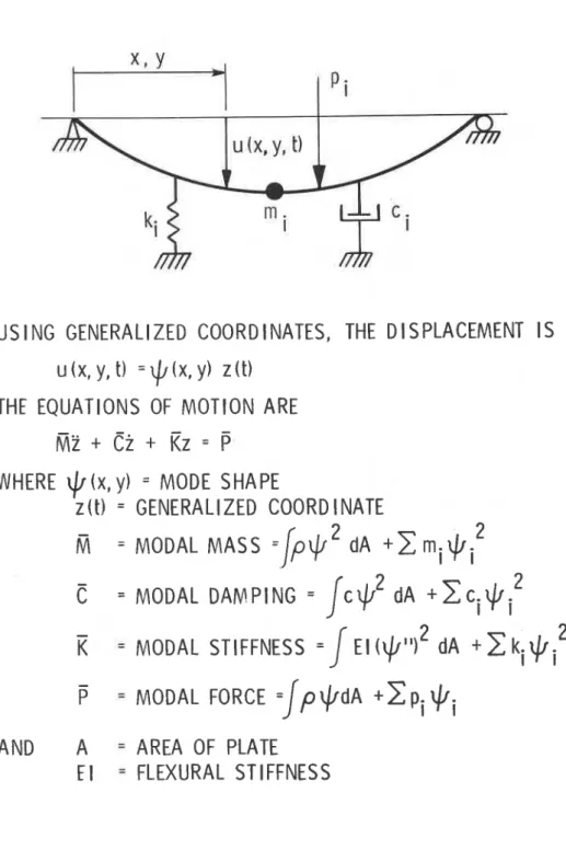
A summary of modal p r o p e r t i e s f o r a s i m p l e beam s t r u c t u r e i s p r e s e n t e d i n F i g u r e 11.Mass
Modal mass and modal damping a r e f u n c t i o n s of t h e s q u a r e of t h e mode s h a p e ( Y , F i g u r e 11). T h i s i s i n c o n t r a s t t o e q u i v a l e n t i n e r t i a l mass i n E q u a t i o n ( 4 ) , which i s a f u n c t i o n of t h e mode s h a p e o n l y t o t h e power of 1. F o r
a
simply-supported p l a t e , t h e modal mass of t h e fundamental mode e q u a l s0.250 M , whereas t h e e q u i v a l e n t i n e r t i a l mass ( M ~ ) a c c o r d i n g t o E q u a t i o n ( 4 ) i s 0.405 M (M i s t h e t o t a l mass of t h e p l a t e ) . Modal mass i s t h e
m a t h e m a t i c a l l y c o r r e c t form f o r s o l v i n g v i b r a t i o n problems a s d e s c r i b e d by t h e e q u a t i o n of motion i n F i g u r e 11. E q u i v a l e n t i n e r t i a l mass a r i s e s f r o m t h e e m p i r i c a l f o r m u l a t i o n of t h e i m p u l s e r e s p o n s e of a s y s t e m h a v i n g
d i s t r i b u t e d mass, and
i s
o n l y a p p l i c a b l e t o t h e c a l c u l a t i o n of peak i m p u l s e r e s p o n s e . It c a n n o t be u s e d a s t h e mass f o r t h e d e t e r m i n a t i o n of n a t u r a l frequency.The a c c u r a c y i n p r e d i c t i n g a. f o r t h e f l o o r sample u s i n g e q u i v a l e n t i n e r t i a l mass (MI) seems t o depend on t h e end and edge c o n d i t i o n s of t h e f l o o r ( T a b l e 7 ) . C o n s i d e r i n g t h e i n h e r e n t v a r i a b i l i t y of t h e t e c h n i q u e , agreement between t h e c a l c u l a t e d and measured v a l u e s of a. f o r t h e s u p p o r t e d end and edge c o n d i t i o n s was e x c e l l e n t . For u n s u p p o r t e d end and edge beams, however, t h e e q u i v a l e n t i n e r t i a l mass model seems t o b e u n s u i t a b l e , a s i s e v i d e n t from t h e l a r g e d i f f e r e n c e between p r e d i c t e d and measured r e s u l t s . A more c o n s i s t e n t f o r m u l a t i o n i s needed, b u t t h i s i s beyond t h e s c o p e of t h i s r e p o r t .
Damping
A s was shown b e f o r e , t h e v a r i a t i o n s i n damping r a t i o s f o r t h e
f u n d a m e n t a l mode w i t h changing p o s i t i o n of t h e p e r s o n c a n be a s s e s s e d u s i n g t h e m a t h e m a t i c a l model shown i n F i g u r e 11. However, t h i s m a t h e m a t i c a l model h a s t o be viewed somewhat a s a n a r t i f a c t , s i n c e t h e p e r s o n s t a n d i n g on t h e f l o o r i s s u r e l y n o t w e l l r e p r e s e n t e d by a s i n g l e d a s h p o t c o n n e c t e d t o t h e ground. A r e a l i s t i c r e p r e s e n t a t i o n of a p e r s o n would r e q u i r e t h e u s e of a multi-degree-of-freedom s y s t e m w i t h many masses and s t i f f n e s s e s , and damping d a s h p o t s n o t connected t o t h e ground. The c o n s i d e r a t i o n of s u c h a model i s , however, beyond t h e s c o p e of t h i s r e p o r t . D e s p i t e t h e a p p a r e n t s h o r t c o m i n g s
on a physical basis, the simple dashpot model gives answers that are in
general agreement with the observed values (Table
5).
Fundamental Natural Frequency
The fundamental natural frequency of the floor is another important
parameter in assessing the vibrational behaviour of a floor system. For a
simply-supported joist floor, the frequency in
Hz can be calculated from:
where
E
=Young's modulus (MPa),
I
=moment of inertia
(mm4),w
=loading
per unit length (N/mm) and
L
=span length
(mm).The fundamental frequency
of the floor sample was calculated assuming fully composite action between
the joist and the concrete slab and a tributary floor area equal to the
joist spacing. Comparisons of calculated and measured frequencies given in
Table 8 show excellent agreement for the cases where end and edge beams were
supported.
For unsupported end and edge beams, the fundamental frequency (f) of
the floor sample can be estimated by Dunkerly's approximation:
L L
where fl
=fundamental frequency of floor with edge and end beams
supported, and f2
=fundamental frequency of unsupported end beams. The
calculation of f2 requires some assumptions regarding the composite nature
of the steel beanrconcrete slab system, and the size of its tributary area.
It was assumed here that one quarter of the floor slab contributes to both
the mass and the stiffness of the end beam element. For the two cases,
fully composite and noncomposite, the following frequencies were obtained
for the
81
mmslab:
f2 (noncornposite) =
6.2
HZ
f2 (composite)
=10.6
HZ
.
Substitution of f2 into Equation (4) gives:
f =
4.7 Hz (noncomposite)
and
f
=5.5
Hz (composite)
.
The comparison with measured values for other floor configurations is
presented in Table
8.
The composite assumption for the end beam gives
better agreement with measurements than the noncomposite one. The effect of
the transverse beam on the frequencies of the fundamental mode in Table 8
was ignored.
DISCUSSION
The s t u d y of t h e dynamic p r o p e r t i e s of t h e f l o o r sample provided a n o p p o r t u n i t y t o a s s e s s t h e i n f l u e n c e of v a r i o u s p a r a m e t e r s t h a t cannot
u s u a l l y be i n v e s t i g a t e d on a c o n s t r u c t i o n s i t e o r i n completed and occupied s t r u c t u r e s . However, t h e f l o o r sample s u f f e r s from one major d i s a d v a n t a g e i n t h a t i t does n o t r e p r e s e n t an a c t u a l f l o o r system. Real f l o o r s e x t e n d o v e r s e v e r a l bays i n both d i r e c t i o n s and c o n t a i n many more s o u r c e s of
s t i f f n e s s and damping such a s w a l l s , p a r t i t i o n s and o t h e r s u p p o r t i n g beams. These a d d i t i o n a l s o u r c e s of s t i f f n e s s can produce s m a l l t o major changes i n mode shapes and n a t u r a l f r e q u e n c i e s and t h u s r e s u l t i n changes t o t h e
v i b r a t i o n r e s p o n s e of t h e f l o o r t o dynamic loading. Modal damping r a t i o s o b t a i n e d f o r people and f o r v a r i o u s s t r u c t u r a l m o d i f i c a t i o n s of t h e f l o o r should t h e r e f o r e n o t be d i r e c t l y employed i n o t h e r s i t u a t i o n s w i t h o u t a p p r o p r i a t e v e r i f i c a t i o n of t h e i r a p p l i c a b i l i t y .
SUMMARY
AND CONCLUSIONSThe dynamic t e s t s on a f u l l s c a l e l a b o r a t o r y f l o o r sample of composite s t e e l j o i s t - c o n c r e t e s l a b c o n s t r u c t i o n i n d i c a t e d t h e following:
1. Mode shapes and n a t u r a l f r e q u e n c i e s can be e v a l u a t e d s a t i s f a c t o r i l y by e x c i t i n g t h e f l o o r system w i t h e i t h e r h e e l impact, s h a k e r impact, o r s h a k e r random e x c i t a t i o n . S e v e r a l p o i n t s of e x c i t a t i o n a r e needed i f a complete s e t of modal p r o p e r t i e s i s d e s i r e d .
2.
Modal damping r a t i o s can be e v a l u a t e d from e i t h e r t h e l o g a r i t h m i c decrement method of f r e e v i b r a t i o n decay from impact, o r from t h e half-power bandwidth o r c u r v e - f i t t i n g methods a p p l i e d t o F o u r i e rspectrum peaks d e r i v e d from t h e f l o o r r e s p o n s e t o random e x c i t a t i o n s o r impacts. The p r e s e n c e of people on t h e f l o o r a f f e c t s t h e measured modal damping r a t i o , e s p e c i a l l y f o r f l o o r s w i t h i n h e r e n t l y low damping.
3 . The c o n t r i b u t i o n of people t o modal damping and t h e amplitude of t h e i n i t i a l peak a c c e l e r a t i o n t o h e e l impact a r e b o t h dependent on t h e l o c a t i o n of t h e p e r s o n s on t h e f l o o r and t h e p o i n t of e x c i t a t i o n . C o r r e c t i o n s f o r t h e s e two e f f e c t s c a n be made from a knowledge of t h e mode shape of t h e f l o o r s l a b .
4. S i g n i f i c a n t d i f f e r e n c e s were found between t h e c a l c u l a t e d e q u i v a l e n t i n e r t i a l mass (MI) and t h e c a l c u l a t e d e q u i v a l e n t mass (MJ) of t h e f l o o r sample. Good agreement was o b t a i n e d between c a l c u l a t e d and measured v a l u e s of t h e i n i t i a l peak a c c e l e r a t i o n a. t o a h e e l impact, f o r t h e c a s e of supported end and edge beams, when t h e e q u i v a l e n t i n e r t i a l
mass
was used. T h i s agreement
i s
a s c r i b e d t o t h e s i m i l a r i t y between t h e a c t u a l mode shape of t h e f l o o r sample and t h e shape implied by t h e i n e r t i a l m a s s model. On t h e o t h e r hand, t h e agreement was poor f o r unsupported edge and end beams. T h i s would i n d i c a t e t h a t t h e i n e r t i a l mass modeli s
i n a p p r o p r i a t e f o r t h e c a l c u l a t i o n of i n i t i a l peaka c c e l e r a t i o n f o r t h e f l o o r sample w i t h unsupported end and edge beams. 5. A d d i t i o n of a suspended c e i l i n g o r a gypsum board c e i l i n g r a i s e d t h e
damping r a t i o of t h e fundamental mode from 0.4% t o a maximum of 0.71% of c r i t i c a l . Although t h i s r e p r e s e n t s a s u b s t a n t i a l p e r c e n t a g e i n c r e a s e ,
i t i s o n l y ' a r e l a t i v e l y s m a l l i n c r e a s e i n a b s o l u t e terms. The most s i g n i f i c a n t i n c r e a s e i n t h e damping r a t i o of t h e fundamental mode occurred when t h e s t e e l - n e o p r e n e sandwich s t r i p s were b o l t e d t o t h e
bottom chord of t h e j o i s t s . For t h e c a s e w i t h supported end and edge beams, a modal damping r a t i o of 1% of c r i t i c a l was obtained.
6 . The agreement between measured and c a l c u l a t e d fundamental frequency of t h e f l o o r sample was good f o r c a s e s where b o t h end and edge beams were e i t h e r supported o r unsupported. For t h e l a t t e r c a s e , t h e assumption of f u l l composite a c t i o n was r e q u i r e d i n c a l c u l a t i n g t h e frequency of t h e end beams. Assuming non-composite a c t i o n f o r t h e end beams gave
(1) Rainer, J.H. and Pernica, G., "Damping of a Floor Sample,"
Proceedings, ASCE-EMD Specialty Conference on Dynamic Response of
Structures, Atlanta, GA, January, 1981, 859-873, NRCC 19457.
(2) Lenzen, K.H., "Vibration of Steel Joist-Concrete Slab Floors," AISC
Engineering Journal,
-
3, 3, 1966, 133-136.
(3) Canadian Standards Association, "Steel Structures for Buildings
-
Limit States Design," CAN3-S16.1-M84, Appendix G, Canadian Standards
Association, Rexdale, Ontario, 1984.
(4) Allen, D.E. and Rainer, J.H., "Vibration Criteria for Long-Span
Floors," Canadian Journal of Civil Engineering,
3,
2, 1976, 165-173,
NRCC 15207.
(5) Clough, R.W. and Penzien, J., Dynamics of Structures, McGraw-Hill
Book Company, New York, 1975, 634 p.
TABLE
1Modal Frequencies for Floor Sample With Supported End and Edge Beams
Mode No.
1
2
3
4
5Across joist
Mode
,--&A
s
Shape
Along joist
- - -
w -u
Floor Conditions Run No. Modal Frequencies,
Hz
81
mm slab2
96.50
9.60
15.75*
17.5
22.0
3
0
81
mm slab with159
6.75
13.25
20.62
17.12
15
x23
mm
161
13.50
transverse concrete beam106
mm
slab with15
x23
mm transverse concrete beamTABLE 2
Modal Frequencies of Floor Sample With Supported or Unsupported End and Edge Beams
Mode No. 1
2
3
4
56
- -Across joist
Mode
-
+-
7 4 - = a -Shape
Along joist
- - -
-
f
JC
End, Edge Beam
Support
Floor Condition
Conditions**
Run No.
Modal Frequencies,
Hz
81
mmslab
u,
u
5
5.47
8.98
12.8*
16.4
11.7
22.0
8, 9, 10
5.43
8.79
81
mm
slab
s,
u
16-19
6.4
8.9
12.8*
16.4
17.6
21.9*
81
mmslab
s,
u
11
1
6.35
8.79
12.70
16.1
17.2
22.0
81
mm
slab
u,
u
146
5.4
8.8
12.6*
16.1
11.4
81
mm
slab
u,
u
147
5.6
9.8
with transverse
concrete beam
81
mm
slab
u,
s
with transverse
concrete beam
106
mmslab
u,
u
166
5.3
9.2
with transverse
169
concrete beam
*Mode shape could not be identified with certainty from available data.
**U
-
unsupported;
TABLE 3
Modal Damping Ratios of Floor Sample
Modal Damping Ratio,
6 ,
%Critical
From
Modal
Logarithmic
End, Edge Beam
Frequency,
Decrement,
Floor Condition Support Conditions* Run No. Mode No.
Hz
Shaker Impact
81
mm slab
S V
s
159
1
6.72
0.48
with transverse
161
1
6.72
0
-46
concrete beam
2
13.50
0.81
81
mmslab
Curve-Fitting
Algorithm of
Spectrum
Analyzer
Shaker
Shaker
Impact
Random
106
mmslab
S V
s
182
1
6.25
0.55
0.56
with transverse
183
1
6.25
0.50
0.56
concrete beam
2
11.62
1.06
0.82
- ---*U
-
unsupported;
S
-
supported.
TABLE 4
I n f l u e n c e of P e r s o n s o n Modal Damping R a t i o s of F l o o r Sample, End and Edge Beams S u p p o r t e d
T o t a l Damping
Modal Frequency, R a t i o , % of D i f f e r e n c e From Hz C r i t i c a l Bare F l o o r
Type o f E x c i t a t i o n
Mode 1 Mode 2 Run No. F l o o r C o n d i t i o n and L o c a t i o n Mode 1 Mode 2 Mode 1 Mode 2
6.72 13.5 160 81 mm s l a b w i t h Shaker impact a t A , 0.46 0.81 t r a n s v e r s e c o n c r e t e b a r e f l o o r beam 3 p e r s o n s n e a r A 3.39 13.5 155 8 1 mm s l a b w i t h Heel impact a t A 1.36 t r a n s v e r s e c o n c r e t e B 1.02 1.33 beam C 1.03 D 0.94 1.21 11.62 182 106 mm s l a b w i t h Shaker impact a t A, 0.55 t r a n s v e r s e c o n c r e t e b a r e f l o o r be am 1 p e r s o n n e a r A 1.40 0.85 2 p e r s o n s n e a r A 2.25 1.70
TABLE 5
Damping R a t i o s f o r Fundamental Mode With One P e r s o n on F l o o r , End and Edge Beams Supported
Damping R a t i o ,
6 ,
% of C r i t i c a l A d j u s t e d f o rHeel Comparable Mode Shape Average f o r F l o o r Impact Bare F l o o r T o t a l Minus R e l a t i v e t o 1 P e r s o n C o n d i t i o n Run No. a t T o t a l (Run No.) Bare F l o o r L o c a t i o n A a t L o c a t i o n A
8 1
mm
s l a b 7 7 A B C D 8 1 mm s l a b 93 A w i t h B suspended C c e i l i n g p l u s D " l i g h t s " 81 mm s l a b 155 A B C DTABLE 6A
Damping Ratios ( 6 , % of Critical) of Fundamental Mode for Various Floor Modifications, 81 mm Slab Unsupported End and Edge Beams
Shaker Impact Heel Impact Shaker Random
From Curve-Fitting From Curve-Fitting Logarithmic Algorithm of Logarithmic Half-Power Algorithm of
Decrement Specturm Analyzer Decrement Bandwidth* Spectrum Analyzer
Natural Record No., Record No., Record No., Record No., Record No., Frequency, Location of Location of Location of Location of Location of Floor Condition Hz Excitation
tS
Excitation SSP Excitation SH Excitation SW Excitation~ W P a) no modifi- 5.41 (0.4)** 135, A 0.91 146, E 0.37 cat ions C Q b) suspended 5.30 99, E 0.62 99, E 0.99 98, A 1.10 97, E 0.47 97, E 0.68 ceiling with 0.91 B 0.90 "lights" C 0.88 D 0.85 c) gypsum board 5.38 104, E 0.44 104, E ceiling d) steel-neoprene 5.8 double 121, E 0.76 121, E 1.07 119, A 0.97 118, E 0.65 1 1 8 , E 0.39
damping strips 6.2 peak 0.77
*Analysis bandwidth = 0.060 Hz.
TABLE 6B
Damping Ratios (5, % of Critical) of Fundamental Mode for Various Floor Modifications, 81 mm Slab Supported End Beams, Unsupported Edge Beams
Shaker Impact Heel Impact Shaker Random
From ~ u r G e Fitting From Curve Fitting Logarithmic Algorithm of Logarithmic Half-Power Algorithm of
Decrement Spectrum Analyzer Decrement Bandwidth* Spectrum Analyzer Natural Record No., Record No.
,
Record No., Record No., Record No.,Frequency, Location of Location of Location of Location of Location of Floor Condition Hz Force 6~ Force 6~~ Force CH Force 5~ Force 5~~ a) no modifi- 5.41 (0.4)** 135, A 0.91 146, E 0.37
cations, unsupported end and edge
beams
i) end and 76, E 77, A 1.19
edge beams 0.91 B 0.85
supported C 0.82
D 0.72
ii) only end 6.38 (0.4)** 112, A 1.25 111, E 0.20 111, E 0.35
beams B 0.95 supported D 0.65 b) suspended 6.20 92, E 0.71 92, E 0.72 93, A 1.67 94, E 0.58 94, E 0.58 ceiling with B 1.35 "lights" C 1.17 D 1.06 c) gypsum board 6.36 109, E 0.44 109, E ceiling d) steelaeoprene 7.8 115, E 1 .O 115, E 114, A 1.74 113, E 0.95 113, E 1.01 damping strips C 1.65 *Analysis bandwidth = 0.060 Hz.
1
TABLE 7Comparison of Measured and C a l c u l a t e d I n i t i a l Peak A c c e l e r a t i o n Amplitudes from H e e l Impacts
I n i t i a l Peak A c c e l e r a t i o n , a.
,
E q u i v a l e n t % g r a v i t y Measured I n e r t i a l E q u i v a l e n tRun No. and Fundamental Mass, Mass, C a l c u l a t e d F l o o r L o c a t i o n of Frequency, MI, Eq. ( 4 ) ,
MJ,
Eq. ( 3 ) , from Eq. ( 2 )C o n d i t i o n Heel Impact Hz kg kg Using MI Using MJ Measured
End and Edge Beams Supported
8 1 mm s l a b 33 A 6.57 6350 3540 4.69 7.18 4.72 B 3.66 3.65 C 3.50 3.65 D 3.15 3.15 81 mm s l a b , 155 A t r a n s v e r s e B c o n c r e t e beam C
D
106 mm s l a b , 190 A t r a n s v e r s e B c o n c r e t e beam CD
End and Edge Beams Unsupported
81 mm s l a b 8 A 5 -43 9 B
10 C
11 D
TABLE
8Comparison of Measured and Calculated Fundamental
Frequencies for Floor Sample
Fundament
a1
Natural Frequency, Hz
-- -
Floor Condition
Run No.
Measured
Calculated
End and Edge Beams Supported
81
mm slab
33 81mm slab
transverse
concrete beam
106 mnslab,
transverse
Iconcrete beam
183 6 . 2 5End and Edge Beams Unsupported
Composite Noncomposit
e
81mm slab
81mm slab,
transverse
concrete beam
106mm slab,
transverse
concrete beam
166-180 5 . 34.3
5 . 23 CONCRETE BEAM ADDED UNDER S U B W 8 x 24 COLUMNS 1 829 rnm HIGH 76 mrn CONCRETE SLAB, INCREASED TO 102 rnm AFTER RECORD N O . 166
X TEMPORARY JACK SUPPORTS
Figure 1 . Layout of f l o o r sample
0 ACCELEROMETER STATIONS ( I TO 28) LOCATION OF DYNAMIC FORCE (A TO E)
Figure 2 . Locations of accelerometer s t a t i o n s (
0
) and dynamic f o r c eF R E Q U E N C Y , H z
Figure
3.
Fourier amplitude spectrum at location 21, run 118, shaker random excitation at locationE,
81 mm concrete slab,steel-neoprene-steel sandwich strips, unsupported end and edge beams
F R E Q U E N C Y , H z
Figure
4.
Fourier amplitude spectrum at location 21, run 115, shaker impact at locationE,
81 mm concrete slab, steel-neoprene- steel sandwich strips, supported end and edge beams0 1 2 3 4 5 6 7
T I M E , s
F i g u r e 5. F r e e v i b r a t i o n decay a t l o c a t i o n s 4 , 5, r u n 182, s h a k e r impact a t l o c a t i o n A, 2 p e o p l e s t a n d i n g a t l o c a t i o n A, 106 mm
c o n c r e t e s l a b w i t h 152 x 229 mm t r a n s v e r s e c o n c r e t e beam, mode 1 , u n s u p p o r t e d end and edge beams
0 . 2 5
0 1 2 3 4 5 6 7
TIME, s
F i g u r e 6. F r e e v i b r a t i o n decay a t l o c a t i o n s 4 , 5, r u n 182, s h a k e r impact a t l o c a t i o n A , mode 1 , 106 mm c o n c r e t e s l a b w i t h 152 x 229 mm t r a n s v e r s e c o n c r e t e beam, u n s u p p o r t e d end and edge beams
a ) L I N E A R A M P L I T U D E 0 . 3 > I-
-
> a @L C3 Z 0-
0 C a @L W -I W 0 0 a -0.3 0 1 2 3 4 5 T I M E , s T I M E , s b ) L O G A R I T H M I C A M P L I T U D E S C A L E ( d B )Figure 7 . Free v i b r a t i o n decay a t l o c a t i o n s 3 , 6 , run 1 6 1 , shaker impact a t l o c a t i o n B , mode 2 , 81 mm concrete s l a b with 152 x 229 mm transverse concrete beam, unsupported end and edge beams
M O D E S H A P E S A C R O S S J O I S T S
Figure 8. Mode shapes and natural frequencies of f l o o r sample, run 5 ,
shaker random e x c i t a t i o n a t l o c a t i o n D , 81 mm concrete s l a b , unsupported end and edge beams
M O D E S H A P E S
A L O N G J O l S T S M O D E S H A P E S A C R O S S J O I S T S
Figure 9. Mode shapes and natural frequencies of f l o o r sample, run 2 9 , shaker impact a t l o c a t i o n D , 81 mm concrete s l a b , unsupported end and edge beams
M O D E S H A P E S A C R O S S J O I S T S
Figure 10. Mode shapes and natural frequencies of f l o o r sample, run 111, shaker random e x c i t a t i o n a t l o c a t i o n E , 81 mm concrete s l a b , supported end beams, unsupported edge beams